Purpose of the fuse mounting block
The figure shows the location of the blocks under the signs A and B.
The mounting areas have one purpose - to place the safety elements in one place. This allows you to quickly and easily find the damaged element without disassembling half the machine.
The external module (under the hood) looks like a black plastic box. Elements responsible for the power supply circuits of the power plant and main equipment are mounted here.
The indoor (cabin) unit is responsible for auxiliary networks and devices. On cars after 2011, the arrangement of individual elements has changed, but the principle remains the same.
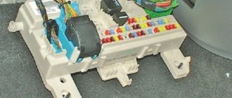
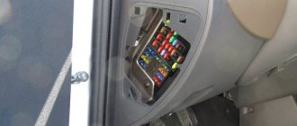
Fuse box in the passenger compartment
It is thoughtfully located under the glove compartment.
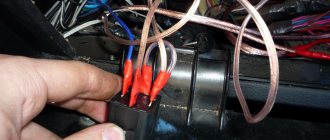
The photo shows the module without a protective cover and lining. Here, each element is responsible for a specific device or circuit. The photo above shows the first generation shield. In the first versions of the machine from 2006-2007, some instruments and elements are missing, which simplifies the design of the module. After 2008, the device was updated, new parts and elements appeared. Therefore, the modified pinout needs to be further described.
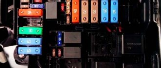
Under the hood
It is closed with a special lid that prevents dust and dirt from entering the compartment. Here the inserts are primarily responsible for the powertrain systems and carrier electronics. To allow installation of additional equipment, the installer has spare sockets.
Fuses Focus 2 dorestayl
The first modifications of the car had a simplified layout of inserts and relays, relative to the last years of production. The modules do not contain batteries for complex devices and equipment.
Fuses for the restyled Focus 2
After the update, the element panel has changed slightly in appearance. The type of device remains the same, the main difference is in the type of power supply and connection.
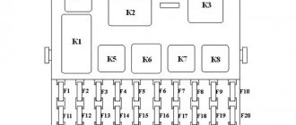
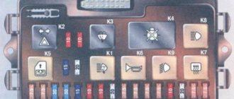
Fuse layout diagram in the Ford Focus mounting block
The fuses in the Ford Focus mounting block are located as follows:
| 1 | 50 60 | 2004-2007: Cooling fan |
| 40 | 2007-2010: Cooling fan | |
| 2 | 80 | Power steering |
| 3 | 60 | Fuse box in the passenger compartment |
| 4 | 60 | Fuse box in the passenger compartment |
| 5 | 80 | Auxiliary heater |
| 6 | 60 | Diesel: Glow plugs |
| 7 | 30 | ABS, stability control pump |
| 8 | 20 | ABS, dynamic stabilization system valves |
| 9 | 20 | The engine control unit |
| 10 | 30 | Heater control unit |
| 11 | 20 | Egnition lock |
| 12 | 40 | Ignition relay (15l) |
| 13 | 20 | Starter |
| 14 | 40 | Heated windshield, right side |
| 15 | 30 | Cooling Fan Relay (Sigma - Non-A/C Options Only) |
| 16 | 40 | Heated windshield, left side |
| 17 | 30 | Electronic Parking Brake (EPB) |
| 18 | 30 | Inverting power amplifier |
| 19 | 10 | ABS |
| 20 | 15 | Sound signal |
| 21 | 20 | Diesel: Auxiliary heater |
| 22 | 10 | Power Steering Module |
| 23 | 30 | Headlight washers |
| 24 | 15 | Diesel: Pre-heater |
| 25 | 10 | Ignition relay |
| 26 | 10 | 2004-2007: Automatic transmission control unit |
| 15 | 2007-2010: Automatic transmission control unit | |
| 10 | ST, RS: Powertrain control module (PCM) | |
| 27 | 10 | A/C compressor clutch |
| 28 | 10 | Diesel: Glow plugs |
| 29 | 10 | Separate climate control system |
| 30 | 3 | Engine control unit, automatic transmission control unit |
| 31 | 10 | Intelligent battery charging |
| 32 | 10 | 2004-2007: 16V+VCT: Ventilation |
| 10 | 2007-2010: Intelligent battery charging | |
| 10 | ST, RS: Injectors | |
| 33 | 10 | Gasoline: Heated oxygen sensors |
| 10 | Diesel: Intercooling air bypass valve | |
| 20 | ST, RS: Heated oxygen sensors | |
| 34 | 10 | Petrol: Injectors, ignition coils |
| 10 | 2004-2007: Diesel: Fuel pump | |
| 35 | 10 | Engine control unit, valves |
| 36 | 10 | The engine control unit |
| Relay | ||
| R1 | Starter interlock (automatic transmission) | |
| R2 | Sound signal | |
| R3 | Reversing lamps (automatic transmission) | |
| R4 | – | |
| R5 | Diesel: Pre-heating 16V+VCT: Ventilation | |
| R6 | Main relay | |
| R7 | Heated windshield | |
| R8 | Ignition | |
| R9 | headlight washer | |
| R10 | Heater | |
| R11 | Air conditioner | |
| R12 | Cooling fan (without A/C) | |
| R13 | Starter | |
| R14 | Power management Cooling fan | |
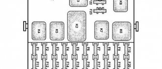
Fuse diagram
The figures above show the engine compartment and interior fuse areas of versions 2002-2005. The location of the parts is relevant for gasoline and diesel engines. The factory decoding will help you understand what the marks on the diagram mean.
In the version after restyling, the location and marking of the inserts differ noticeably, which can cause certain difficulties.
Fuse box pinout
The procedure is complex and is only suitable for use in specialized workshops. The module cannot be repaired if part of the board is burned out - the unit is completely replaced.
Where are they located?
Regardless of the generation before restyling or restyling, year of manufacture and modification, the location of the fuse boxes is no different. Also, the position is the same in station wagon, sedan and hatchback bodies.
The head module is located near the battery and covered with a special cover. The auxiliary part on the 2004 car with right-hand drive is located on the other side of the car, which makes access to the panel easier.
The rear luggage compartment socket is also installed in one place; after reworking the car, its location has not changed.
An important point is the location of the fuse links themselves. The updated system has more fuses and relays, and in the Max version there are even more elements. Looking at the installer's diagram, you can also see that the parts are in completely different places.
Starter fuses and relays
On a pre-Restyle car, the elements responsible for the launcher are located under the numbers F13 and R13 in the engine compartment. The updated version of the machines is equipped with a remote fuse mounted on a special bracket.
Radio tape recorder
Element 58 of the internal block is responsible for powering music in the first generation. The radio is powered by insert 68. The bifurcated line allows for stable operation of the tape recorder and other units as power increases.
The second generation of the car involves powering the audio system from part No. 112.
Cooling Fan
It is turned on using several elements at once. Fuse F1 and 15 of the external unit are located in the most visible place and have the same purpose, regardless of car modifications. The relay for turning on the radiator blower installation is located in different places. For a car without air conditioning, the relevant number is R12, and where there is a heating system without air conditioning, if it breaks down, you need to pay attention to R14.
Trunk
The power supply system for the socket at the end of the cabin is complex.
In the first generation, fuse 59 is responsible for the operation of the contact group; energy is supplied to the auxiliary element through insert 39, which also serves as cigarette lighter protection. After the update, the manufacturer immediately thought about the power supply to the trailer terminal and installed one element on the socket and lamps of the trailer hitch. This is part #119.
The standard trunk lid lock contacts pass through the central locking system. The head module acts as a fuse and controller. There are no relays here; in the hatchback and sedan versions, their role is played by buttons.
After opening the cargo compartment, the lighting is activated. Inserts No. 80 and 104 for versions before and after restyling are responsible for the lamp circuit.
Wiper fuse and relay
The first version of the car had protective elements for the power supply circuit and washer control removed from the blocks - the parts were located near the motor.
After updating the components, the manufacturer placed the front fuse at number 129, and the rear fuse at position 131. There is one fuse for both sides and is located under the hood (R6).
Reverse
Initially, fuse 84 was responsible for the operation of the lamp and the inclusion of the reverse gear light. After the update, element 141 began to perform its function.
The relay is only on the machine - these are R1 and 3 of the main mounting block.
Generator fuse
On the second generation Focus, the protective insert is located in the engine compartment, on the wing. The element is embedded in the power cores of the device. It can be found in the break in the positive wire.
Heater fuse
R10 and F10 are responsible for powering the heater motor. It is unacceptable to connect additional equipment to the elements - this may cause overload of the circuit.
Dimension fuse
Voltage is supplied through inserts No. 45, 48 and 71 of the cabin unit. In the new version of the car, the location of the part corresponds to insert No. 110/113/135. Fuses 124 and 125 are responsible for adjusting the dimensions on the left and right sides.
Relyushka is also located here under number K5.
central locking
It is controlled by fuse F55 and 77. It supplies power to the relay installed in the central locking unit in the car door. For the restyling version, it is moved to the R3 position.
Power window fuse
The system is powered by inserts No. 63 and 127 for lowering and raising the glass. The old generation of the machine is equipped with inserts in the lift modules.
Wiper
The headlight washer system is fed through main unit fuse F23.
In winter, users often encounter burnout of 47/136 inserts (before and after restyling). The elements supply voltage to the heating of the pressure system jets and the pump motor.
The wipers are powered through the 50/129 elements, and the rear window is powered through the 78/131 numbers of the standard circuit.
The windshield washer drive system is controlled by relay R9.
Light fuse
The operation of the high and low beam lamps is adjusted separately for each side. In FF2 this is:
- 37/38 for left and right optical element high beam mode;
- 60/61 low for each side.
In the version after restyling, the indicated elements correspond to the numbers:
- 139/140;
- 142/143.
The headlight switches are located near the light module.
Fog lights
Standard elements on the car are controlled by one fuse 69 and 116 for the first and second generation of cars. At the same time, the power supply to the left and right parts of the onboard fog lights is looped into one circuit.
Such a PTF power system is a disadvantage - if the insert burns out, the entire circuit fails completely.
Headlight adjustments
The standard corrector operates through fuse 66 in the first generation. The version after restyling is equipped with an insert in the module itself.
Number plate illumination
The system operates through inserts No. 117/73 for new and old mounting blocks.
Immobilizer
The security module of the machine is a separate unit with a self-sufficient system of protection against voltage surges and overloads. There is no need to look for the corresponding fuse in the mounting block.
Ignition fuse and relay
The system is complex and confusing. There are 2 fuses 12 and 25 of the engine compartment. There is also a main relay R6 and an auxiliary relay R8.
Signal fuse
Stop lamps in different versions of the car are powered through 74 and 132 for the old and new generations, respectively.
The sound signal protection is installed in the device housing. The relay is mounted in the engine compartment under the number R2.
Accumulator charging
The generator system has its own fuse and relay, located separately. The parts can be found on the right fender of the car.
Climate control
Relay R11 supplies power to the climate system inside the car. The safety insert is marked in the block as R29.
Dashboard
The standard insert F46 of the cabin module is responsible for powering the dashboard in the old generation.
The new version is powered from the battery through fuse 107. Additional tidy options are covered by part 108. After turning the lock, voltage is supplied through element 114.
Lambda probe
The photo shows the location of the oxygen sensor fuse.
Parktronic
The separate parking assistant module is equipped with separate fuses and relays. You should look for elements near the block.
Airbags
The units are protected by 65/122 safety inserts for the first and second generation of the car.
Heated seats
The new generation of cars has this option. The heating elements are protected by insert No. 121 or 86. The element is located in the interior block of the system.
ABS fuse
There are three inserts in the traction control system. Elements F7/8 protect sensors and hydraulic drives from power surges. Element F19 is responsible for the operation of the ABS control unit.
The new generation does not have such a system; it is imitated by a more advanced device.
Speedometer
The fuse is missing and not located in the mounting block. The electronic module is responsible for protection against overvoltage; it also reads data from the sensor and transmits it to the device.
Turn signals
For them, inserts are not mounted in the main block. The elements are located under the dashboard to make them easier to access during maintenance. The devices are located near the driver's feet.
Mirror fuses
The rear view elements are also protected by separate inserts. 42 and 123 are responsible for heating the reflective surface for the old and new versions of the car.
The latest generation also has the ability to fold the mirrors; the servo drive is protected through element 79.
Door fuse
The electrical equipment of the doors of the dorestyle version is looped on one element No. 55. After updating there were two parts, one for each No. 133/134 for the left and right sides.
Heated windshield
There is no heating device as such in most versions of the machine. Heating occurs in a classic way - using a cabin heater.
ESP fuse
Insert No. 19 of the engine compartment is responsible for the new generation traction control system.
Alarm fuse
Modern systems do not have remote protection elements against power surges. You should not look for insertions in common blocks.
Automatic transmission fuse
The electronics of the standard machine are brought out through the main block insert numbered 30 and 75.
Power steering
The power steering unit is also located here. Element 22 is mounted under the hood.
Cruise control fuse
Depending on the configuration and year of manufacture of the car, the power to the system passes through inserts 53/29 of the engine compartment block or 20 and 30.
Relay Focus 2: restyling and dorestyling
Due to the similarity of the internal design of the car before and after the update, the main elements are in the same places and are responsible for strictly defined devices.
Engine relay
Element R6 is located in the main block. Through it, the power plant and the process of its operation are controlled.
Generator voltage regulator relay
It is removed from the mounting block and is located on the fender of the car. This design is relevant for everyone, including VALEO.
Solenoid relay
On the Focus it is located in a classic way - on the starter itself. A Bosch unit is used here. A fairly reliable installation that meets the modern requirements of motorists.
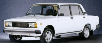
Ford Focus 2 fuses and relays, electrical diagrams
This car model is very common; the second generation of Focuses was produced from 2004 to 2011. Despite the reliability of the brand, any car sooner or later develops problems related to electrical systems, instruments and equipment. If you purchased a used car, it is not known what the previous owner did with it, so before operation it is worth checking all the fuses and relays of the Ford Focus 2. Therefore, during operation, defects, loss of contacts and other unpleasant surprises may appear.
The new Ford Focus 2 may also experience some electrical problems, and over time, poor-quality soldering, oxidation of contacts, etc. make themselves felt. To cope with all possible problems, you need to be fully armed.
Replacing parts
The cause of the block board failure is a sudden voltage drop. The process melts the contacts and can kill the device. Water ingress is also a common cause. Any electronics are afraid of moisture and dust.
Replacing the generator regulator relay
After you have learned how to check the voltage regulator and determine that the module is faulty, you should replace it. The procedure itself looks extremely simple. The wiring chip is disconnected from the terminal. Next, the block is unscrewed and replaced with a new element.
Replacing the windshield wiper relay
You will need to pull the device body. Insert the working part into the vacant space.
Replacing the wiper relay
The procedure is similar to changing other elements.
Replacing the solenoid relay
It is more difficult to replace the retractor element, but it is possible to do it yourself.
- Place the car on a level surface and raise the handbrake all the way.
- Remove the terminals from the battery.
- Get under the car and unscrew the 9 engine protection screws.
- Next, the starter itself is shown. Here you will need to disable the chips of the interfering elements of the on-board circuits.
- Next, you need to unscrew the three screws that secure the starter to the engine block.
- After this, you can completely remove the device from the machine.
- The last stage is to turn off the retractor. To do this, three screws are unscrewed and the part is simply removed from the seat.
Installation of a new part is carried out in reverse order.
Unit repair
The main breakdowns are:
- burning of contact groups;
- oxidation of terminal blocks.
Any auto electrician can fix the above breakdowns. If the device board burns out, it must be replaced entirely - the circuit cannot be repaired.
Focus 2 does not start, the starter does not turn, the relay clicks
Factors may be the cause.
- The starter motor burned out.
- The retractor or bendix is faulty.
- Wiring is damaged.
- There is not enough battery power.
Focus 2: wipers do not work, relay clicks
Problems with wipers can be similar. To understand the problem, just pay attention to the system components.
- Cleaner gear motor.
- Check equipment wiring.
Symptoms of a problem
First, let's figure out when you should worry about the operation of the heater. Let's say you got into your car in the morning, turned on the heater, and did not hear the characteristic noise of the fan. This indicates that the stove has broken down. The sooner you eliminate it, the better.
Another option
– the stove turns on only at certain speeds. This malfunction is quite difficult to detect immediately. You can wait a little while eliminating it. At least not to do diagnostics immediately after discovering a problem; nevertheless, in such a situation the car can be operated. Also, in some cases, the fan may work, but the stove will not heat. In this case, you should first pay attention to the tap that allows coolant access to the stove. Perhaps you just forgot to open it. If it is open, you need to look for the cause of the breakdown.