Information on the “five” schemes is intended for self-repair of a car in case of minor problems with electrical equipment. The electrical circuits are divided into several blocks (for ease of viewing via a computer or phone), there are files in the form of a single picture with a description of each element - for printing on a printer. Years of production of this model: from 1979 to 2010. At the end of December 2010, AvtoVAZ stopped producing it due to low demand for the VAZ-2105 model. By this time, 2 million cars had already been produced.
Scheme of carburetor VAZ 2105
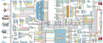
This is a color diagram of the electrical equipment of the VAZ 2105. At the top of the image on the right are the colors of the wires, at the bottom are the designations of the elements.
1 – block headlights, 2 – side direction indicators, 3 – battery, 4 – starter activation relay, 5 – electro-pneumatic valve for the carburetor forced idle economizer, 6 – starter, 7 – carburetor microswitch, 8 – generator 37.3701, 9 – headlight cleaners , 10 – sound signals, 11 – spark plugs, 12 – engine compartment lamp, 13 – oil pressure warning lamp sensor, 14 – coolant temperature indicator sensor, 15 – ignition distributor, 16 – brake fluid level sensor, 17 – ignition coil, 18 – windshield wiper, 19 – electric headlight washer motor, 20 – electric windshield washer motor, 21 – control unit for the electro-pneumatic valve of the carburetor forced idle economizer, 22 – ignition switch, 23 – ignition relay, 24 – relay-interrupter for direction indicators and hazard warning lights, 25 – reverse light switch, 26 – brake light switch, 27 – windshield wiper relay, 28 – mounting block, 29 – socket for portable lamp, 30 – glove box lighting lamp, 31 – VAZ-2105 cigarette lighter, 32 – heater fan electric motor, 33 – parking brake warning lamp switch, 34 – carburetor air damper warning lamp switch, 35 – three-lever switch, 36 – hazard warning switch, 37 – instrument lighting switch, 38 – external lighting switch, 39 – lamp switches located in the door pillars, 40 – fog light circuit fuse, 41 – oil pressure warning lamp, 42 – rear fog light switch, 43 – fuel reserve warning lamp, 44 – instrument cluster, 45 – battery charging warning lamp, 46 – breaker relay parking brake warning lamp, 47 – interior lamps, 48 – parking brake warning lamp, 49 – carburetor air damper warning lamp, 50 – warning lamp block, 51 – rear fog light warning lamp, 52 – rear window heating warning lamp, 53 – brake fluid level indicator lamp, 54 – voltmeter, 55 – side light indicator lamp, 56 – turn signal indicator lamp, 57 – speedometer 2105, 58 – headlight high beam indicator lamp, 59 – heater fan switch, 60 – rear window heating switch, 61 – additional resistor for the heater electric motor, 62 – plug connector for connecting the bar, 63 – rear lights, 64 – license plate lights, 65 – fuel gauge sensor, 66 – rear window heating element.
Wiring diagram 2105 - full view:
VAZ 2105 fuse block diagram, complex or spot replacement
If individual elements of automotive electrical systems refuse to cooperate, an experienced car owner will definitely begin searching in the fuse box. Most likely, one of them, the one responsible for a specific block, has burned out. Due to the fact that the VAZ 2105 fuse diagram is quite simple, finding the problem (if it really lies in a burnt-out fuse element) is easier than ever. It is enough to look into the diagram and find a blown fuse “on the ground”.
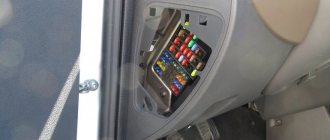
In the VAZ 2105, the fuse box (also known as the mounting block) is located under the hood, near the windshield on the left side, when viewed from the driver’s seat. However, it all depends on the year of manufacture of the car (on the first “fives” the fuse box was located inside the cabin, on models of later production it moved under the hood). You can check either “on the ground” or by reading the user manual in more detail.
In order to check the fuses for their functionality, it is enough to remove the cover (by the way, the diagram is always applied to the inside of the cover so that it is always, so to speak, at hand). A screwdriver is enough to remove the cover.
On cars whose year of manufacture is quite distant from the current one, you should check the correct installation of fuses - first of all, from the point of view of compliance with the permissible current in the circuit controlled by the fuse. Unlike the “kopek”, in the “five” the permissible current strength varies for the fuses - from 7.5 amperes for the rear fog lights and signaling device to 20 in the circuit of the rear window heating elements, electric motor and sound signal. More powerful fuses, which inexperienced drivers often try to install, only lead to quick breakdowns, and the cost of repairs turns out to be much higher than the price of even several dozen fuses.
With a lack of knowledge in the field of automotive electrical engineering, the VAZ 2105 fuse box diagram may seem too complicated, although, of course, this is absolutely not the case. In this case, it is better to replace the entire fuse box (especially if you are sure that this is the problem). Replacing the unit as a whole is a little more expensive, but you won’t have to understand the intricacies of the location of each fuse. At least this time.
1 (8A) Rear lights (reversing light). Heater electric motor. Indicator lamp and rear window heating relay (winding). 2 (8A) Electric motors for windshield wiper and washer. Electric motors for headlight cleaners and washers. Windshield wiper relay. Relay for cleaners and headlight washers (contacts). 3(8A) Reserve. 4(8A) Reserved. 5 (16A) Rear window heating element and heating switch relay (contacts). 6 (8A) Cigarette lighter. Plug socket for portable lamp. 7 (16A) Sound signals. 8 (8A) Direction indicators in hazard warning mode. Switch and relay-interrupter for direction indicators and hazard warning lights in emergency mode. 9 (8A) Generator voltage regulator. 10 (8A) Direction indicators in turn indication mode and the corresponding warning lamp. Indicator lamps for fuel reserve, oil pressure, parking brake, brake fluid level. Battery charge indicator lamp. Instrument cluster. Voltmeter. Carburetor pneumatic valve control system. Parking brake warning light relay. Rear lights (brake lamps). Lamps for interior body lighting. 11 (8A) Right headlight (high beam). Coil of the relay for turning on the headlight cleaners (with the high beams on). 12 (8A) Left headlight (high beam). Indicator lamp for turning on the high beam headlights. 13 (8A) Left headlight (side light). Right rear light (side light). 14 (8A) License plate lights. Engine compartment lamp. Indicator lamp for turning on side lighting. 15 (8A) Right headlight (side light). Left rear light (side light). Cigarette lighter lamp. Instrument lighting lamps. Glove box lighting lamp. 16 (8A) Right headlight (low beam). Coil of the relay for turning on the headlight cleaners (with the low beam on). 17 (8A) Left headlight (low beam)
Second version of the scheme
- block headlights
- side turn signal repeater
- battery
- lamp relay for monitoring battery charging
- electropneumatic valve
- carburetor microswitch
- generator
- headlight glass cleaner
- sound signal
- starter
- engine TDC indicator lamp
- engine compartment lamp
- oil pressure warning light sensor
- coolant temperature gauge sensor
- fluid level sensor in the hydraulic brake reservoir
- candles
- windshield washer pump motor
- distributor cap
- distributor
- ignition coil
- electric motor of the pump serving the headlight washers
- electronic control unit
- diagnostic block (installed on some cars)
- windshield wiper relay
- relay-interrupter for direction indicators and hazard warning lights
- wiper motor
- brake light switch
- electric motor of the heater (stove)
- additional resistance
- portable lamp socket
- reverse light switch
- Handbrake warning lamp switch
- relay and fuse box
- low beam headlight relay
- headlight high beam relay
- horn relay
- Relay for windshield wipers and headlight washers
- rear window defroster relay
- glove compartment lamp
- cigarette lighter
- dome light switches
- interior lamp
- rear window defroster switch
- hazard warning switch with warning lamp
- warning lamp block
- rear fog light warning lamp
- hand brake warning lamp
- warning lamp indicating a drop in brake fluid level
- windshield wiper and washer lever
- handbrake warning lamp relay
- horn switch
- outdoor light switch
- turn signal switch
- headlight switch lever
- egnition lock
- instrument light switch
- rear fog light switch
- instrument cluster
- warning lamp indicating insufficient oil pressure
- fuel reserve warning lamp
- fuel level indicator
- battery charging warning light
- water temperature indicator
- instrument lighting lamps
- voltmeter
- speedometer
- indicator lamp for turning on external lighting
- turn signal indicator lamp
- high beam warning lamp
- three-position heater fan switch
- rear window defroster
- fuel level and reserve indicator sensor
- rear light block
- license plate lights VAZ 2105
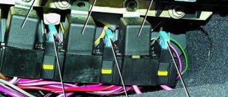
Block parsing
The VAZ mounting block can become unusable at any time. Therefore, you should always have a fuse diagram in your car in case you need to replace them.
If a certain electrical unit fails, you should not immediately take on the electric motor or spark plugs. There is a high probability that the malfunction has occurred in the safety block.
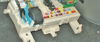
In the old-style VAZ 21053, the unit is located directly under the dashboard next to the left door, that is, inside the cabin. In the new VAZ 21053, the safety block is located outside under the hood, closer to the windshield, on the driver's side. The latest models of the “five” are most often equipped with an external fuse block.
To open the unit, you need to remove the cover by pushing it upward. On any cover there is a diagram of the VAZ mounting block, which reflects the location of the fuses with a description of the electric current for each of them. In older VAZ 2105 models, the most precise installation of each fuse in accordance with the required current strength is important.
Scheme of VAZ-21053 with generator 37.3701
1 — block headlights; 2 — side direction indicators; 3 - battery; 4 — starter activation relay; 5 — carburetor electro-pneumatic valve; 6 — carburetor microswitch; 7 - generator 37.3701; 8 — gearmotors for headlight cleaners*; 9 — electric motor of the engine cooling system fan*; 10 — fan motor activation sensor*; 11 — sound signals; 12 — ignition distributor; 13 — spark plugs; 14 — starter VAZ-2105; 15 — coolant temperature indicator sensor; 16 — engine compartment lamp; 17 — oil pressure warning lamp sensor; 18 — ignition coil; 19 — brake fluid level sensor; 20 — windshield wiper gearmotor; 21 — carburetor electro-pneumatic valve control unit; 22 — electric motor of the headlight washer pump*; 23 — electric motor of the windshield washer pump; 24 — brake light switch; 25 — windshield wiper relay; 26 — instrument lighting regulator; 27 — relay-breaker for alarm and direction indicators; 28 — reverse light switch; 29 — plug socket for a portable lamp**; 30 — cigarette lighter; 31 — glove box lighting lamp; 32 — mounting block (a jumper is installed instead of a short-circuit relay); 33 — lamp switches on the front door pillars; 34 — lamp switches on the rear door pillars; 35 — lampshades; 36 — parking brake warning lamp switch; 37 — switch for the carburetor air damper warning lamp; 38 — alarm switch; 39 — three-lever switch; 40 — ignition switch; 41 — ignition relay; 42 — external lighting switch; 43 — rear fog light switch; 44 — fog light circuit fuse; 45 — oil pressure warning lamp; 46 — instrument cluster; 47 — fuel reserve warning lamp; 48 — fuel level indicator; 49 — battery charge indicator lamp; 50 — coolant temperature indicator; 51 — control lamp for the carburetor air damper; 52 — parking brake warning lamp; 53 — control lamp block; 54 — rear fog light indicator lamp; 55 — control lamp for heated rear window; 56 — brake fluid level warning lamp; 57 - voltmeter; 58 — speedometer; 59 — control lamp for external lighting; 60 — turn signal indicator lamp; 61 — control lamp for high beam headlights; 62 — heater fan switch; 63 — rear window heating switch with backlight*; 64 — block for connecting the bar; 65 — heater fan electric motor; 66 — additional resistor of the heater electric motor; 67 — rear lights; 68 — pads for connecting to the rear window heating element; 69 — sensor for level indicator and fuel reserve; 70 — license plate lights.
Useful: Diagram of Lada Kalina VAZ-1117, VAZ-1118, VAZ-1119
VAZ 2105 injector diagram
1 – electric motor of the engine cooling system fan; 2 – mounting block; 3 – idle speed regulator; 4 – electronic control unit; 5 – octane potentiometer; 6 – spark plugs; 7 – ignition module; 8 – crankshaft position sensor; 9 – electric fuel pump with fuel level sensor; 10 – tachometer 2105; 11 – control lamp “CHECK ENGINE”; 12 – car ignition relay; 13 – speed sensor; 14 – diagnostic block; 15 – nozzle; 16 – adsorber purge valve; 17, 18, 19 – injection system fuses; 20 – ignition relay for the injection system; 21 – relay for turning on the electric fuel pump; 22 – intake pipe electric heater relay; 23 – electric heater of the intake pipe; 24 – intake pipe heater fuse; 25 – oxygen concentration sensor; 26 – coolant temperature sensor; 27 – throttle position sensor; 28 – air temperature sensor; 29 – absolute pressure sensor;
- A – to the “plus” terminal of the battery;
- B – to terminal “15” of the ignition switch;
- P4 – relay for turning on the fan motor.
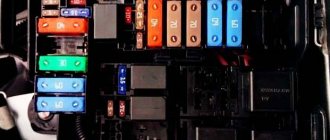
Fuse and relay diagram 2105
Until 1988, the fog lamps in the rear lights and the fog lamp warning lamp were protected by fuse 17 of the mounting block. Since 1988, they began to be protected by a separate fuse, which is located in a plastic case in the wiring harness near the car's fog light switch.
Mounting block 2105-3722010-02
Mounting block 2105-3722010-08
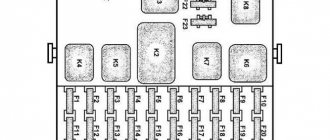
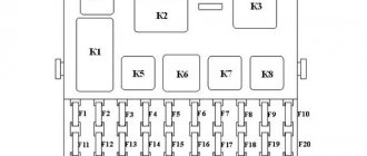
Mounting block diagram 2105-3722010-08
K1 Relay for turning on the heated rear window K2 Relay for turning on the headlight washer cleaners K3 Relay for turning on the sound signal (jumper) K4 Relay for turning on the electric fan motor K5 Relay for turning on the high beam headlights K6 Relay for turning on the low beam headlights
Circuits protected by fuses
F1 (10A) Reversing lamps. Heater electric motor. Rear window heating indicator. Rear window heating relay (winding). F2 (10A) Wiper motors. Windshield washer pump motors. Windshield wiper relay. Relay for cleaners and headlight washers (contacts). F3 (10A) Reserved. F4 (10A) Reserved. F5 (20A) Rear window heating element. Relay for turning on the heated rear window (contacts). F6 (10A) Cigarette lighter. Watch VAZ-2105. F7 (20A) Sound signal. Horn relay. Radiator cooling fan electric motor. Radiator cooling fan motor activation relay (contacts) F8 (10A) Direction indicators (in hazard warning mode). Turn signal indicator (in hazard warning mode). Relay-breaker for direction indicators and hazard warning lights. Hazard warning switch with warning lamp. F9 (7.5A) Rear fog lamps. Indicator for switching on the rear fog lamps. F10 (10A) Direction indicators (in turn indication mode). Turn signal interrupter relay. Turn signal indicator. Tachometer. Fuel indicator. Fuel reserve indicator. Parking brake indicator. Indicator of insufficient oil pressure in the engine lubrication system. Coolant temperature gauge. Voltmeter. Indicator of emergency condition of the working brake system. Battery charge indicator. Electric fan relay. Generator excitation winding (generator 37.3701). F11 (10A) Interior lamps. Brake light bulbs. Luggage compartment lamps. F12 (10A) High beam headlights (right headlight). F13 (10A) High beam headlights (left headlight). High beam indicator. F14 (10A) Front side light (left headlight). Rear marker light (right light). License plate lights. Indicator for turning on side lights. F15 (10A) Front side light (right headlight). Rear marker light (left light). Cigarette lighter lamp. Instrument lighting lamp. Glove box lighting lamp. Clock (lighting lamp). F16 (10A) Low beam headlights (right headlight). Headlight wiper relay (relay coil). F17 (10A) Low beam headlights (left headlight).
In the old-style VAZ 21053, the unit is located directly under the dashboard next to the left door, that is, inside the cabin. In the new VAZ 21053, the safety block is located outside under the hood, closer to the windshield, on the driver's side. The latest models of the “five” are most often equipped with an external fuse block. To open the unit, you need to remove the cover by pushing it upward. On any cover there is a diagram of the VAZ mounting block, which reflects the location of the fuses with a description of the electric current for each of them. In older VAZ 2105 models, the most precise installation of each fuse in accordance with the required current strength is important.
Diagram of the VAZ 2104 2105 mounting block
P1 — relay for turning on the heated rear window; P2 - relay for turning on headlight cleaners and washers; PЗ - relay for turning on sound signals; P4 - relay for switching on the electric motor of the engine cooling system fan; P5 - headlight high beam relay; P6 — headlight low beam relay; A - the order of conditional numbering of plugs in the mounting block blocks. The outer number with the letter “Ш” in the plug designation is the block number, and the inner number is the conventional number of the plug. The plugs of the blocks without color marking are conventionally shown in brown
Car modifications
VAZ-2105 . The base model was produced in 1979 with a 1.29-liter carburetor engine producing 63.6 horsepower. It was equipped with a 4-speed gearbox.
VAZ-21050 . The same model of the five, but with a 5-speed gearbox.
VAZ-21051 . Modification with a VAZ-2101 carburetor engine with a volume of 1.2 liters and a power of 58.7 horsepower, a 4-speed gearbox as in the basic version.
VAZ-21053 . Modification with a VAZ-2103 engine with a volume of 1.45 liters and a power of 71.4 horsepower. It was equipped with both 4 and 5-speed gearboxes.
VAZ-21053-20 . Modification with a VAZ-2104 injection engine with distributed injection, volume 1.57 liters and 82 horsepower. The gearbox is 5-speed.
VAZ-21054 . A special modification for the needs of no less special services, such as the traffic police, the Ministry of Internal Affairs and the FSB. It was equipped with a VAZ-2106 carburetor engine with a volume of 1.57 liters and a power of 80 horsepower. In addition, an additional gas tank and battery were installed.
VAZ-21054-20. Another special modification, but with a more powerful VAZ-21067 engine with distributed injection, 82 horsepower, which meets the Euro-3 environmental standard. The gearbox is 5-speed.
VAZ-21055 . A vehicle for taxi service was produced in a small batch with a VAZ-341 diesel engine with a volume of 1.52 liters and a power of 50.3 horsepower.
VAZ-21057 . The export version of the VAZ-21053 car was produced from 1992 to 1997 for countries with left-hand traffic, respectively, the steering wheel was located on the right. The engine complied with the Euro-1 environmental standard.
VAZ-21058 . The same right-hand drive car, based on the VAZ-21050, was produced from 1982 to 1984.
Lada Nova . Export modification of the VAZ-2105, produced mainly for the German markets. VAZ-2105 engine, 4-speed gearbox. Produced from 1981 to 1997.
VAZ-21059 . Another special modification of the car was equipped with a Wankel VAZ-4132 rotary piston engine, with a volume of 1654 cm3 and a power of 140 horsepower. This car was produced in a small batch for the needs of the traffic police, the Ministry of Internal Affairs and the KGB.
VIS-2345 . Semi-frame pickup truck, which was produced from 1995 to 2006 by VAZINTERSERVIS JSC based on modifications of the VAZ-21053 and VAZ-21054.
LADA-2105-VFTS . A sports car with a forced VAZ-2106 engine, using WEBER 45 DCOE carburetors. The engine capacity was 1.6 liters and the power was 160 horsepower at 7000 rpm. It was equipped with spur-cut 4 and 5-speed gearboxes, with cam clutches. In order to reduce the weight of the car, in 1986 the standard doors were replaced with aluminum ones.