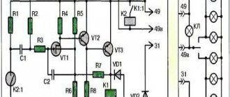
What are the VAZ 2110 fuse box relays responsible for?
K1 – relay for monitoring the health of light bulbs; K2 – front wiper relay; K3 – repeater and alarm relay; K4 – low beam relay; K5 – high beam relay; K6 – additional relay; K7 – relay for turning on the heated rear window; K8 – backup relay (not installed on 110 series vehicles);
F1-F20 in the diagram are fuses. The circuits in the car are protected by fuses based on a certain rated current (in A). The battery charging circuit, generator circuit, ignition and engine starting are exceptions.
To replace a faulty fuse, first find the one that has blown, then eliminate the reason why it was damaged and then install a new one. Below is a list of fuses and information on each one.
* Never replace fuses with jumpers, this can lead to failure of various components and elements, including failure of the wiring tracks in the fuse box and even a car fire.
What does the relay kit with fuse box do?
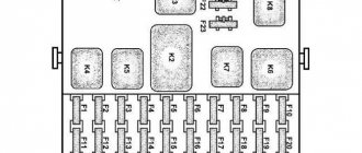
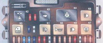
Layout of fuses and relays in the main mounting block of the VAZ-2110
The above diagram describes the location of the main relay kit and fuse box. The following elements are located here:
- K1 is a type of relay responsible for monitoring the health of a set of light bulbs;
- K2 – this component is associated with the operation of the front pair of wipers;
- K3 – behind this designation lies a breaker relay that regulates the operation of the repeater and the vehicle’s alarm sign;
- K4 and K5 – a pair of relays for the injector, which is responsible for turning on the low/high beam headlights of the VAZ-2110;
- K6 - an additional type of relay required to replace one of the burned out ones from the main unit;
- K7 - this element is responsible for turning on the heating function on the rear window;
- K8 - like K6, is a backup relay.
Tip: If you notice the main signs of a faulty oxygen sensor. You should look at the fuses first. If everything is in order in the mounting block, then you should seek help from a car service for diagnostics.
What are the fuses on the VAZ-2110 responsible for?
Decoding fuses.
License plate lamps. Instrument lighting lamps. Side light indicator lamp. Trunk light. Left side marker lamps
Left headlight (low beam)
Left headlight (high beam)
Right fog lamp
Door window motors
Portable lamp (socket)
Engine cooling fan electric motor. Sound signal
Rear window heating element. Relay (contacts) for turning on the heated rear window
Recirculation valve*. Windshield and headlight cleaners and washers ( wiper fuse ). Relay (coil) for turning on the rear window heating
Starboard side marker lamps
Right headlight (low beam)
Right headlight (high beam). High beam warning lamp
Left fog lamp
Electrically heated seats. Trunk lock lock
Relay-breaker for direction indicators and hazard warning lights (in hazard warning mode). Hazard warning lamp
Interior lighting lamp. Individual backlight lamp. Ignition switch illumination lamp. Brake light bulbs. Clock (or trip computer)
Glove box lighting lamp. Heater controller ( heater fuse ). Cigarette lighter fuse for VAZ 2110, VAZ 2111, VAZ 2112.
Locking door locks. Relay for monitoring the health of brake light lamps and side lights. Direction indicators with warning lamps. Reversing lamps. Generator excitation winding. On-board control system display unit*. Instrument cluster. Clock (or trip computer)
Rear fog lamps
Electrical diagram of VAZ 2115 - 20 cars (left half):
1 – headlights; 2 – fog lights; 3 – air temperature sensor; 4 – electric motor of the engine cooling system fan; 5 – blocks connected to the wiring harness of the ignition system; 6 – engine compartment lamp switch; 7 – block for connection to a single-wire type audio signal; 8 – sound signal; 9 – washer fluid level sensor; 10 – front brake pad wear sensors; 11 – oil level sensor; 12 – generator; 13 – engine compartment lamp; 14 – coolant temperature indicator sensor; 15 – starter; 16 – battery; 17 – relay for turning on fog lights; 18 – coolant level sensor; 19 – brake fluid level sensor; 20 – reverse light switch; 21 – windshield wiper gearmotor; 22 – oil pressure warning lamp sensor; 23 – block for connecting to the rear window washer electric motor; 24 – windshield washer electric motor; 25 – instrument cluster; 26 – mounting block. Conventional numbering of plugs in blocks: A - block headlights; B — electric fuel pump block; C — blocks of the mounting block, ignition switch, windshield wiper gearmotor; D — interior lamp
Circuits protected by additional fuses (all fuses are 15 A) on the VAZ-2110:
Additional fuses: 1 – ignition module, controller; 2 – canister purge valve, vehicle speed sensor, oxygen (heating) sensor, air flow sensor; 3 – fuel pump relay, fuel pump, injectors.
Additional relays: 4 – electric fan relay; 5 – electric fuel pump relay; 6 – main relay (ignition relay).
There is a fog lamp fuse installed in the niche of the instrument panel behind the mounting block:
Lada 2111 Agneska › Logbook › relays and fuses
The main fuses and relays on the VAZ-2110, 21102, 21103, 2112 are located on the left side of the steering wheel, just below. The figure shows the designations on the fuse mounting block/
Fuse number Current strength, A Circuits protected by fuse F1 5 Lamps for license plate lights. Instrument lighting lamps. Side light indicator lamp. Trunk light. Left side side light lamps F2 7.5 Left headlight (low beam) F3 10 Left headlight (high beam) F4 10 Right fog lamp F5 30 Door window electric motors F6 15 Portable lamp F7 20 Engine cooling fan electric motor. Sound signal F8 20 Rear window heating element. Relay (contacts) for turning on the heated rear window F9 20 Recirculation valve. Windshield and headlight cleaners and washers. Relay (winding) for turning on the heated rear window F10 20 Reserve F11 5 Side light bulbs on the right side F12 7.5 Right headlight (low beam) F13 10 Right headlight (high beam). Indicator lamp for turning on the high beam. F14 10 Left fog lamp F15 20 Electric seat heating. Trunk lock lock F16 10 Relay-interrupter for direction indicators and hazard warning lights (in hazard warning mode). Hazard warning lamp F17 7.5 Interior lighting lamp. Individual backlight lamp. Ignition switch illumination lamp. Brake light bulbs. Clock (or trip computer) F18 25 Glove box lighting lamp. Heater controller. Cigarette lighter F19 10 Door locking. Relay for monitoring the health of brake light lamps and side lights. Direction indicators with warning lamps. Reversing lamps. Generator excitation winding. On-board control system display unit. Instrument cluster. Clock (or trip computer) F20 7.5 Rear fog lamps
Electrical diagram of VAZ-2112
Designations: 1 – Headlight, 2 – Klaxon, 3 – Main radiator fan, 4 – Starter, 5 – Battery, 6 – Generator 2112, 7 – Gearbox limit switch (reverse), 8 – Actuator in the front passenger door, 9 – Power window enable relay, 10 – Starter relay, 11 – Heater fan, 12 – Electric heater partition drive, 13 – Main pump, 14 – Washer reservoir sensor, 15 – Driver’s door actuator, 16 – Front passenger window selector, 17 – Unlock button fifth door, 18 – Heater fan resistance unit, 19 – Main wiper motor, 20 – Driver’s window lift selector, 21 – Front passenger’s window lift motor, 22 – Central locking, 23 – Exterior light switch, 24 – Brake fluid leakage sensor, 25 – Pump additional, 26 – Driver's window lift motor, 27 – PTF on indicator, 28 – PTF switch, 29 – Dashboard, 30 – Heated glass on indicator, 31 – Heated glass switch, 32 – Steering column selector switch, 33 – PTF relay, 34 – Ignition switch, 35 – Main fuse block, 36 – Illumination of heater controls, 37 – Hazard warning button, 38 – Heater control controller, 39 – Glove compartment lighting, 40 – Glove compartment lid end cap, 41 – Cigarette lighter, 42 – BSK – display unit, 43 – Ashtray illumination, 44 – 12V socket, 45 – Instrument lighting switch, 46 – Actuator in the right rear door, 47 – Right rear passenger window selector, 48 – Clock, 49 – Right rear passenger window motor, 50 – Brake limit switch (closed – pedal is pressed), 51 – Left rear passenger window motor, 52 – Left rear passenger window selector, 53 – Actuator in the left rear door, 54 – Turn signal, 55 – Handbrake limit switch (closed – handbrake on), 56 – Rear wiper motor , 57 – Navigator's lamp, 58 – Interior lamp, 59 – Temperature sensor in the heater, 60 – Limit switch for the open front door, 61 – Limit switch for the open rear door, 62 – Trunk light, 63 – Rear optics (on the body), 64 – Rear optics (on the fifth door), 65 – License plate illumination.
The letters indicate the terminals to which it is connected: A – Front speaker on the right, B – Radio, C – Injector harness, D – ESD diagnostic connector, D – Front left speaker, E – Diagnostic connector for the heater controller, G – Rear right speaker, W – Rear left speaker, I – BC connector, K – glass heater thread, L – fifth door actuator, M – Additional brake light.
Wiring diagram VAZ-2112 injector 16 valves - full view
VAZ 2112 fuse box
If some devices on your VAZ 2112 car have stopped working, fuses or relays may be to blame. At the very least, the first thing you need to do is check them, and then draw some conclusions regarding the malfunctions. Correct diagnosis of many electrical problems will allow you to accurately determine the cause of the inoperability of a particular unit. To find out what fuses and relays do and how to find the right one, read this article.
Scheme
K1 – relay for monitoring the health of light bulbs; K2 – front wiper relay; K3 – repeater and alarm relay; K4 – low beam relay; K5 – high beam relay; K6 – additional relay; K7 – relay for turning on the heated rear window; K8 – backup relay (not installed on 110 series vehicles);
F1-F20 in the diagram are fuses. The circuits in the car are protected by fuses based on a certain rated current (in A). The battery charging circuit, generator circuit, ignition and engine starting are exceptions.
To replace a faulty fuse, first find the one that has blown, then eliminate the reason why it was damaged and then install a new one. Below is a list of fuses and information on each one.
Diagram and location of the VAZ-2110, VAZ-2111 and VAZ-2112 fuse box
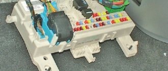
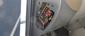
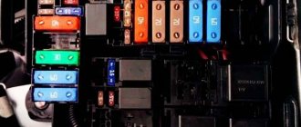
We invite you to familiarize yourself with the diagram and location of the fuse box on the VAZ-2110, VAZ-2111 and VAZ-2112. The fuse and relay box in the VAZ-2110 is located in the car interior a little to the left and above the pedals.
This is how it looks in the interior; the main relays are marked in the photo and all the fuses on the block are numbered.
VAZ 2110 fuse diagram
What are the VAZ 2110 fuse box relays responsible for?
K1 – relay for monitoring the health of light bulbs; K2 – front wiper relay; K3 – repeater and alarm relay; K4 – low beam relay; K5 – high beam relay; K6 – additional relay; K7 – relay for turning on the heated rear window; K8 – backup relay (not installed on 110 series vehicles);
Where is the cooling fan relay on the VAZ-2110
In order for everything to work correctly in the VAZ-2110 engine, it is necessary to maintain a certain temperature.
This temperature range is achieved using a cooling fan, which, as a rule, comes with an electric drive. Its activation and deactivation is carried out automatically. Moreover, if the machine contains a carburetor engine, then TM 108 is used, and in the case when an injection engine is used, a controller is used. This article will tell you where the cooling fan relay is located on a VAZ-2110 car. If the fan is controlled by switching on, it is important that the temperature setting of the housing sensor is observed. The sensor is considered faulty when its temperature has reached the switch-on level, and the cooling motor has not worked. To check, you should close the contacts of the sensor, then check whether the fan works; if so, then the sensor needs to be replaced with a new one.
There are times when closing the contacts does not help and the fan still does not work, then according to the diagram, the integrity of the fuse with the supply wires is checked.
In order to start the cooling fan of the machine in which the injection engine is located, an electronic controller is used. Temperature conditions are pre-entered into the device software and range from 100 to 105 degrees. If the temperature sensor is faulty, then a system error is selected on the controller, and the cooling fan is activated when the car engine is turned on.
A number of breakdowns occur in which the controller does not detect the breakdown, and as a result, when the required temperature reaches 105 degrees, the fan simply does not start. To perform the test, remove the temperature sensor connector while the engine is running. If the system is working properly, the sensor will start the cooling fan, and by returning the connector to its original position, the fan will turn off. In case of damage to the circuit, check the quality of the relay, fuse and underwater wires. Everything must be installed exclusively according to the diagram. To carry out express checks, they bridge terminals 30 and 87 of the fan relay, which are located in the heating shaft. To make it easier to find, look in the passenger seat area.
When the fan is activated, connect the control lamp, the housing and output 86 of the relay, then the relay will operate and the fan will start automatically. At the same time, it is necessary to manipulate such a circuit only when the relay is located in the connector block. Here it is recommended to look at the controller and the wire, the relay connector with pin 46, if there is a breakdown in one of them. If a specific click of the relay did not occur, but a positive signal goes from the main relay to pin 85, or there was a click, but the cooling fan did not start, then this indicates a breakdown of the relay and the need to replace it.
What does the second set of fuse boxes do?
The symbols F1-F20 indicated below in the electrical diagram are the elements that characterize the set of fuses. The electrical circuit in a VAZ-2110 car is protected using fuses based on the specific calculation of the model for the rated current value specified upon purchase.
At the same time, fuses are not responsible for the quality operation of the circuit consisting of a sample battery, a separate type of generator circuit, the ignition system and engine valve starting. To replace a faulty fuse in this mounting block, follow the following plan:
- Find a fuse that has mechanical damage or its body has burned out;
- According to the instructions, determine and eliminate the reason why it turned out to be faulty;
- Install a new fuse using the backup model.
Tip: Never try to replace a fuse with special jumpers. In the future, this will lead to failure of those devices that are assigned to this fuse.
Diagram with designations for the second set of fuses in the block
All fuses are divided according to their interaction with electrical equipment as follows:
- F1 (current 5A) - fuse responsible for the set of lamps that illuminate the license plate, the entire instrument panel, including the side lights and lighting in the trunk.
- F2 (current 7.5A) - element that regulates the low beam on the left headlight.
- F3, F4 (current 10A) - responsible for the operation of high beam in the left headlight and right fog lamp, respectively.
- F5 (with a current of 30A) - is responsible for the electric window motor at the front and rear car doors.
- F6 (with a current of 15A) - refers to the operation of a portable lamp.
- F7 (with a current of 20A) - regulates the operation of the fan motor in the cooling system of a 16-valve engine, as well as the operation of the sound signal.
- F8 (with a current of 20A) - supplies current to the heating elements located on the rear window. In addition, together with the contacts from the relay, it transmits current to the windshield.
- F9 (with a current of 20A) - is responsible for the operation of the recirculation valve. It also interacts with the windshield wiper and washer sensors and headlights.
- F10 (with a current of 20A) - is a backup fuse.
- F11 (with a current of 5A) - regulates the operation of lamps with side lights on the starboard side.
- F12 and F13 (with a current of 10A) - both fuses regulate the operation of the right headlight, responsible for the low/high beam, respectively.
- F14 (current 10A) - adjusts the light from the left fog lamp.
- F15 (with a current of 20A) - interacts with the electric heating of the driver and passenger seats. Protects the car from unauthorized blocking of the central locking in the trunk.
- F16 (with a current of 10A) - transmits current to the breaker relay to ensure the operation of the direction indicator of the left and right headlights, and is also used to give an emergency signal (when using the emergency signal mode on the VAZ-2110).
- F17 (current 7.5A) - works with the car interior lighting lamp, brake light lighting, individual lighting of the ignition system switches and regulates the operation of the trip computer.
- F18 (with a current of 25A) - illuminates the glove compartment, supplies current to the heating system controllers and the cigarette lighter on the dashboard.
- F19 (with a current of 10A) - is responsible for the operation of the door locks, and also informs the driver about the presence of a malfunction in the brake light lamps or side light elements.
- F20 (current 7.5A) - works with the lamps of the rear pair of fog lights of the VAZ-2110.