Fuses and relays in the cabin
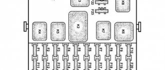
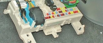
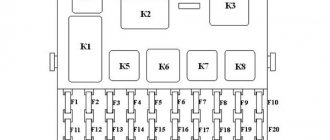
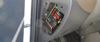
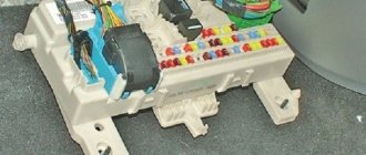
The fuse and relay box is located inside the car under a cover on the instrument panel to the left of the steering column.
2005-2011
Circuit breakers
F1 (5A)
- Lighting of switches and controls
- Left side marker lights
F2 (7.5A)
- Low beam right headlight
F3 (10A)
- High beam right headlight
F4 (10A)
- Right fog lamp
F5 (30A)
- Power window system
- Electric sunroof
F6 (15A)
- Portable lamp socket
F7 (20A)
- Sound signals
- Electric mirrors
F8 (20A)
- Heated rear window
- Heated exterior mirrors
- Light control module (LCM)
F9 (20A)
- Glass cleaners and washers
- Additional interior heater
F10 (20A)
- Cigarette lighter
F11 (5A)
- Side lights on the starboard side
- License plate light
F12 (7.5A)
- Low beam left headlight
F13 (10A)
- Left high beam
- Headlight high beam indicator
F14 (10A)
- Left fog lamp
F15 (20A)
- Electric door lock system
F16 (10A)
- Alarm
- Direction indicators
F17 (7.5A)
- Lighting lamps
- Brake light switch
F18 (25A)
- Heater
- Switch for heated rear window and exterior mirrors
F19 (10A)
- Instrument cluster
- Reversing light switch
F20 (7.5A)
- Rear fog lights
F21 (10A)
- Spare fuse
F22 (20A)
- Spare fuse
F23 (30A)
- Spare fuse
Relay
K1
- Absent
K2
- Windshield wiper relay
K3
- Turn signal interrupter relay
K4
- Low beam relay
K5
- High beam relay
K6
- Additional (unloading) relay
K7
- Heated rear window relay
K8
- Fog light relay
2012-2014
Circuit breakers
F1 (5A)
- Side light left
F2 (5A)
- Side light right
F3 (7.5A)
- Low beam headlights right
F4 (7.5A)
- Low beam left
F5 (10A)
- High beam headlights right
F6 (10A)
- Left high beam headlights
F7 (7.5A)
- Fog light
F8 (20A)
- Door lock
F9 (10A)
- Alarm
F10 (10A)
- Cl. 5 XP1 KP
- Reversing lamp switch
- class 1 speed sensor
- class 4 central lamps
- class 2 hazard switches
F11 (30A)
- Window lifters
F12 (20A)
- Cigarette lighter
- Seat heating
F13 (20A)
- Sound signal
F14 (20A)
- Heated tailgate glass
- Heated exterior mirrors
- Light control module (LCM)
F15 (20A)
- Cont. 11 X2
- Wiper switch
- Wiper
- Rear heater switch
F16 (10A)
- Right fog lamp
F17 (10A)
- Left fog lamp
F18 (25A)
- Heater
F19 (7.5A)
- Brake light switch
- Lighting lamps
F20 (5A)
- Mirror control
F21 (10A)
- Air conditioning compressor
F22 (15A)
- Plug sockets
Relay
K1
- Fog lights
K2
- Fog lights
K3
- High beam
K4
- Low beam
K5
- Unloading relay
K6
- For engines ZMZ 40904, 40905: Additional heater
K7
- Compressor
K8
- Direction indicators
- Alarm
K9
- Windshield wiper interrupter with pause adjustment
2014-2019
Circuit breakers
F1 (10A)
- RK "Dymos" class 15
F2 (15A)
- Interior socket
F3 (10A)
- Air conditioning compressor
F4
- 2014-2015 (5A): Mirror control
- Electrical package control unit, terminal 30
F5 (7.5A)
- Brake light switch
- Interior lamps
- Glove box light
- Luggage compartment lamp
F6
- 2014-2015 (25A): Heater
- Heating and air conditioning system
F7 (10A)
- Left fog lamp
F8 (10A)
- Right fog lamp
F9 (20A)
- Wiper switch
- Wiper
- Driver switch block
- Rear passenger switch block
- Rear body heater
- Auxiliary heater switch
F10 (20A)
- Heated tailgate glass
- Heated mirrors
- Light control module (LCM)
F11 (20A)
- For ZMZ-51432 engines: Sound signal
F12 (20A)
- 2014-2015: Cigarette lighter
- Seat heating
- Cigarette lighter
F13 (30A)
- RK "Dymos" class 30
F14
- 2014-2015 (30A): Window lifters
- Window regulators (driver's door module)
F15
- 2014-2015 (10A): Cl. 5 XP1 KP
- off reverse lights
- class 1 speed sensor
- class 4 central lamps
- class 2 hazard switches
- Cl. 34 instrument cluster
F16
- 2014-2015 (10A): Hazard warning
- Airbag
F17
- 2014-2015 (20A): Door lock
- Media system (radio with audio player)
F18
- 2014-2015 (7.5A): Fog light
- Differential lock
F19 (10A)
- Left high beam headlights
F20 (10A)
- High beam headlights right
F21 (7.5A)
- Low beam left
F22 (7.5A)
- Low beam headlights right
F23 (5A)
- Side light right
F24 (5A)
- Side light left
F25 (60A)
- Heated windshield
F26 (10A)
- Reserve
F27 (10A)
- Reserve
F28 (30A)
- Reserve
F29 (25A)
- Reserve
F30 (20A)
- Reserve
Relay
K1
- Fog light relay
K2
- 2014-2015: Relay for turning on the heated glass of the tailgate and mirrors
K3
- High beam relay
K4
- For ZMZ-40905 engines: Relay for additional electric heater pump
- Low beam relay
K5
- 2014-2015: Low beam relay
- Auxiliary interior heater relay
K6
- A/C compressor relay
K7
- 2014-2015: Turn signal and hazard warning light switch
- Relay for turning on the heated glass of the tailgate and mirrors
K8
- Windshield wiper interrupter with programmable pause
K9
- Additional (unloading) relay
K10
- Heated windshield relay (unloader)
- Fuel tank switching relay (for vehicles with UAZ switchgear)
K11
- Heated windshield timing relay
K12
- 2016-2019: Rear axle differential lock relay
Blocks under the hood
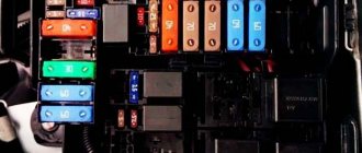
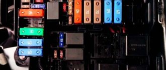
Fuse and relay box
It is located under the hood on the left side, next to the battery and is closed with a protective cover.
Scheme
Explanation of fuses
| F1 | Sound signal |
| F2 | Not installed |
| F3 | Electric fan 2 |
| F4 | ABS (ESP) |
| F5 | Devices |
| F6 | Gasoline pump |
| F7 | Starter |
| F8 | Electric fan |
| F9 | Integrated microprocessor engine control system (CMPSUD) |
| F10 | ABS (ESP) |
| F11 | Pre-start heater |
| F12 | Pre-start heater |
| F13 | Pre-start heater |
| F14 | Not installed |
| F15 | Not installed |
| F16 | Not installed |
| F17 | 60/90A Mounting block, Heated windshield |
| F18 | ABS (ESP) |
| F19 | Mounting block |
Relay
| R1 | Starter relay, electric fan relay 1 |
| R2 | Heater relay, Tailgate washer window time relay (old style unit) |
| R3 | Heater relay, Horn relay (old style unit) |
| R4 | Horn relay, CMPS UD relay (old-style unit) |
| R5 | Relay CMPS UD, Electric fan relay (old style unit) |
| R6 | Electric fan relay, Electric fuel pump relay (old style unit) |
| R7 | Electric fuel pump relay, Electric fan relay (old style unit) |
| R8 | Electric fan relay, air conditioning relay (old style unit) |
| R9 | Compressor relay (old style unit), engine control relay |
| R10 | Recirculation flap control unit relay (old style unit), starter relay 2 |
Additional blocks
Battery block
On the positive terminal of the battery on cars with automatic transmission, there may be an additional fuse block consisting of 2 high-power 100A fuse links protecting the fuse blocks.
Air conditioning relay and fuse box
It is located on the right under the hood of the car.
Scheme
Glow plug relay and power fuse
The glow plug relay and the glow plug power fuse for vehicles with an Iveco engine are located under the hood on the left side on the front panel.
general description
| F1 | 7.5A A/C compressor clutch |
| F2 | 30A Fan 1 |
| F3 | 30A Fan 2 |
| F4 | 60A Glow Plug Power Fuse |
| Relay | |
| K1 | Interior heater fan relay |
| K2 | Recirculation flap relay 1 |
| K3 | Recirculation flap relay 2 |
| K4 | Compressor clutch relay |
| K5 | Fan relay 1 |
| K6 | Fan relay 2 |
| K7 | Glow plug relay |
Replacing the main fuse - UAZ Patriot, 2.7 l., 2021 on DRIVE2
Hello everyone! So I was not spared the problem of burning main fuse contacts (described here www.drive2.ru/c/536767284102835476/) The solution to the problem is obvious - replacing the fuse.
Some find a way out of the situation by bending the clamps more tightly, or by applying battery terminal grease to the contacts. I consider this a half measure.
Having smoked the forum and taking on board the advice of experienced people, a BRP-4 unit, a meter of copper wire, and several terminals were purchased at the GAZ store
Full size
Block with burnt contacts. Three power fuses 60A, 40A, 60A - removed
Full size
Using a 10mm wrench, unscrew the M6 nut and remove the red power wire coming from the battery. Using wire cutters we bite off three thick wires that protect our fuses (pink, brown, red)
Full size
We take a new BRP-4 block, install fuses of the rating we need (60, 60, 40, 40 reserve). We power the block with three wires (you can use one thick one, but I didn’t find it)
Full size
Having tried to cram three terminals onto one stud and realizing that nothing would come of it, I bit them off and soldered three wires into one terminal. Later I will replace this pigtail with one thick wire.
Full size
We solder the terminals to the previously bitten off wires that go to consumers
Full size
We power the BRP-4 from the old unit. Don’t forget to return the thick red wire from the battery there.
Full size
We install wires going to consumers.
Having done all this work and read the report from the outside, here is what I would like to advise: 1. Instead of a pigtail of three red wires, it is better to install one thick one.2.
It is better to increase the wires to consumers (red, pink, brown) by 30 centimeters and throw each one into a corrugation. Then it will be possible to place the BRP-4 somewhere on the engine shield or fender liner.
Now, due to short wires, it just lies on the cover of the old unit.
Something like this. Sincerely.
Price: 500 ₽ Mileage: 42,000 km
What are they needed for
As in any other vehicle, the UAZ Patriot fuse box is designed to extend the life of the vehicle's electrical system . All main electrical circuits are protected by low melting point fuses. This allows:
- divide the circuits into two groups (control and power);
- prevent overloading of electrical wiring.
As a result, the correct operation of UAZ Patriot fuses will allow you to avoid serious problems with electrical equipment in the event of surges in the system. If the voltage increases, the fuse will blow, so you will not have access to just one specific option. Otherwise, the entire electrical system would be at risk.
Video review of UAZ Patriot fuses:
Replacement features
To replace burned-out disposable circuit breakers, parts with the same current and voltage ratings should be prepared. As a temporary solution, it is possible to install an element of a higher rating in order to replace it with the required one in the near future. It is strictly not recommended to replace the fuse with a coin or twisted wire.
Tools include a set of flathead screwdrivers, a power block wrench, tweezers, plastic pliers or a spatula. In poor lighting conditions, a portable rechargeable head-mounted flashlight is recommended.
To check the integrity of the fuses in the interior module, you need to open the cover by turning the fixing screw and pull it out. On the inside of the cover there is explanatory information, including markings and pinouts.
First you should look for the burnt part visually. There may be traces of burning on it. If the housings are made of high-quality plastic, then there will be no traces of combustion and the elements must be removed one by one with tweezers or tongs.
The car accessories market offers products integrated with a high-impedance light bulb or LED, which light up and glow after the fusible link burns out, which makes it much easier to find the faulty part. The parts in the engine compartment module are checked and changed in the same way.
In some cases, 60 and 80 A fuses are installed separately in the power module, located in the engine compartment and closed with a snap-on plastic cover. They are attached to the terminal pads with nuts or bolts, which ensures a reliable connection without chatter and melting of housings and contacts. When replacing, the cover snaps off, the bolts or nuts are unscrewed, the burnt jumper is removed, and a new one is installed in its place. The fasteners are screwed in, the lid is put in place and snapped into place.
Every 32,000 km of the vehicle, perform the following maintenance work on the starter:
1. Remove the starter from the engine. 2. Check the condition of the commutator and brushes. Make sure that the brushes do not jam in the brush holders. If the brush height is less than 6 mm, replace them. 3. Disassemble the starter. Replace worn parts. 4. When assembling, lubricate the bearings and shaft journals with engine oil. Lightly lubricate the splined part of the shaft, drive outlet bushings, pins and lever axis with Litol-24 grease.
When I was looking for why the starter might not work, I found this picture from the instruction manual for UAZ vehicles.
Safety precautions when performing work
When replacing electrical fuses, it is necessary to use tweezers made of non-conducting materials. This will prevent voltage transfer from the circuit to the adjacent electrical fuse.
Before replacing, you must make sure that there is no short circuit in the circuit. A new electrical fuse is installed with the power circuit turned off.
When installing, you must pay attention to the amperage indicated on the product. Installing a more powerful product may lead to overheating and fire of the insulating layer of the wiring.
An element with a lower current rating will not withstand the load of the electrical circuit and will burn out.
Installing a homemade electrical fuse (bug) is strictly prohibited. The maximum load of such a device has not been determined. If a short circuit occurs, it may cause a fire.
From the above it follows that the fusible element block of the UAZ Hunter car is necessary to protect the electrical wiring from overloads and short circuits. The models are equipped with two blocks, the location of which is described above. Some car modifications are equipped with an additional unit.
Possible improvements to the mechanism
The operation of the generator on UAZ vehicles raises many questions and problems. This primarily concerns old structures and connections. The radical method is to completely replace the generator with installation on a suitable pulley removed from the old device, or select a new one. Due to the fact that nowadays UAZs are used as off-road vehicles for hunting, fishing or extreme sports, a large amount of additional electrical equipment is installed on them.
The standard UAZ generator cannot cope with the increased load and requires replacement of individual parts or the entire device in the event of, for example, a stator short circuit. But you can also modify the old mechanism by installing additional diodes in the rectifier unit. Motorists modify the voltage regulator. And if it is a new model, then a three-level element with an external control unit is installed. The best results, of course, are obtained by replacing with a foreign generator (for example, from Toyota, 120A). The modification comes down to only replacing the crankshaft pulley.
Safety precautions when performing work
When replacing electrical fuses, it is necessary to use tweezers made of non-conducting materials. This will prevent voltage transfer from the circuit to the adjacent electrical fuse.
Before replacing, you must make sure that there is no short circuit in the circuit. A new electrical fuse is installed with the power circuit turned off.
When installing, you must pay attention to the amperage indicated on the product. Installing a more powerful product may lead to overheating and fire of the insulating layer of the wiring.
An element with a lower current rating will not withstand the load of the electrical circuit and will burn out.
Installing a homemade electrical fuse (bug) is strictly prohibited. The maximum load of such a device has not been determined. If a short circuit occurs, it may cause a fire.
From the above it follows that the fusible element block of the UAZ Hunter car is necessary to protect the electrical wiring from overloads and short circuits. The models are equipped with two blocks, the location of which is described above. Some car modifications are equipped with an additional unit.
Helpful care tips
Some basic tips:
- Parts are purchased in advance individually or in sets, always from original brands and in trusted stores.
- The insulation of wires and cables, as well as contact connections in mounting blocks, are periodically inspected. If the integrity of the insulation is compromised and the contacts are loose, the wiring and contact blocks should be replaced.
- The module covers under the hood are periodically opened to check for moisture and dried to prevent short circuits.
It is advisable to trust the performance of operations 2 and 3 to professionals in specialized auto repair shops during scheduled technical inspections, when changing the oil or repairing other components of the car.
Main faults of the UAZ-469 starter
What to do if the armature does not rotate when you turn on the starter.
| Probable cause of the malfunction | Remedy |
| Contact between brushes and commutator is broken | Remove the starter from the engine, disassemble it and eliminate the cause of the malfunction |
| There is no contact in the starter traction relay switch | Disconnect the wires from the starter, remove the switch cover with terminals. If the contacts are burnt, clean them. Rotate severely burnt contacts 180° around their axis |
| Broken connections inside the starter or in the traction relay | Repair the starter in a workshop |
| There is no reliable contact in the ignition switch at terminal “C” | Check the circuit using a test lamp connected to terminal C and ground. If there is no voltage at terminal “C” in the position corresponding to the starter turning on, replace the ignition switch |
| The winding is broken or the contacts in the additional relay are burnt | Check the circuit with a test lamp. The lamp connected to terminal “K” of the additional relay and ground should light up when the starter is turned on. If the lamp does not light, then disassemble the relay and clean the contacts |
| The armature is stuck in the sleeve of the electromagnet coil | Clean the armature, relay and bushing from dirt. If there is displacement of the traction relay relative to the starter lever, have it repaired in a workshop. |
What to do if, when the starter is turned on, the engine crankshaft does not rotate or rotates at a low speed.
| Probable cause of the malfunction | Remedy |
| Battery is discharged or faulty | Check the battery and replace if necessary |
| Short circuit of the armature or field coils or the armature touching the poles | Repair the short circuit or send the starter to a workshop for repair. |
| The engine crankshaft is difficult to turn | In winter, warm up the engine |
| The starter power supply circuit is broken due to loose wire ends | Inspect the entire starter power circuit, tighten all clamps |
| Severely worn bearings | Send the starter to a workshop for repair |
What to do if, when turned on, the starter shaft rotates at a high speed, but does not turn the engine crankshaft.
| Probable cause of the malfunction | Remedy |
| Broken flywheel teeth | Change the crown |
| Roller freewheel slips | Change the starter drive |
What should you do if, when you turn on the starter, you hear a repeated strong knock of the traction relay and the gear on the ring gear, but the engine crankshaft does not turn.
| Probable cause of the malfunction | Remedy |
| There is no reliable contact in the clamps, especially on the battery | Check and tighten clamp bolts |
| Battery is discharged or faulty | Check and charge the battery or replace it |
| The holding winding of the traction relay is faulty or its contact with ground is poor. | Replace the winding or ensure reliable winding contact |
What to do if the starter does not turn off after starting the engine.
| Probable cause of the malfunction | Remedy |
| The drive jams on the armature shaft | Disassemble the starter and eliminate the cause of the jamming |
| Sintering contacts of a traction relay switch or an additional relay | Fix the problem or replace the relays with new ones |
What to do if the starter switches on automatically when the car is moving.
| Probable cause of the malfunction | Remedy |
| The locking part of the ignition switch is stuck | Replace the ignition switch |
Lighting, light and sound alarm system UAZ-469
