Auto manufacturers today use many technological solutions to ensure more comfortable driving. One of such devices is CBKE. What is the central unit of body electronics Kalina 2 needed for, what functions does it perform and what malfunctions are typical for it - read in this article.
Description of CBKE
Unlike the first Kalin models, the second versions and Luxury equipment use an electrical package control unit instead of traditional relays to control the electronics. This device combines many functions, we suggest you familiarize yourself with them in more detail.
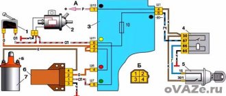
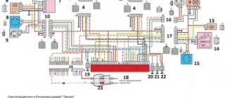
Connection diagram of elements and outputs of the CBEK
Functions
The electrical package control unit is designed to perform the following functions:
- Alarm. If the car's anti-theft system detects a break-in attempt, thanks to the CBKE, it will transmit information about this to the car owner's control panel.
- Windshield wiper system control. Moreover, we are talking about both manual and automatic control (if the car is equipped with an electrical package control unit marked 21900-3840080-20).
- The device performs the function of controlling the windshield and rear window heating systems. This unit also controls the heating elements of the side rear-view mirrors.
- The electrical control unit also monitors the performance of the optics, both in manual and automatic control modes. In particular, we are talking about low-beam headlamps, side lights, and DRLs.
- Separately, we should highlight the function of ensuring the functionality of the high-range lighting.
- Turning lights, as well as light signaling.
- Vehicle interior lighting.
- The device monitors the performance and energy saving of devices belonging to the category of internal lighting of the car.
- Monitoring the state of the central lock, as well as performing the functions of locking and unlocking the locks themselves from the key, from buttons installed in the car interior, as well as in the doors.
- Another option is to open the luggage compartment lid using a button installed in the cabin.
- An equally important function is the control of electric drives, in particular, we are talking about power windows, as well as side rear-view mirrors.
- Heating system for driver and passenger seats.
- Luggage compartment lighting unit (video author - Vladimir Kostyuchenkov).
Typical faults
If the electrical package control unit fails for some reason, this can lead to the following problems:
- Failure to operate power windows. Of course, before disassembling the control module, you should make sure that the window regulators do not work precisely because of it. It would be logical to first check the safety element, as well as the lift control unit, which is built into the driver's door. In practice, it often happens that the cause of power window failure is poor wiring contact on the unit itself.
- The optics stopped working - low beam, turn signals, etc. In this case, the safety elements, light sources and steering switch are first checked. There is a possibility that the reason lies in a broken contact directly on the switch; if this is the case, then they should be re-soldered. If the reason is that the unit is not working, it will need to be dismantled and disassembled in order to find the burnt-out element and re-solder it. If soldering does not help solve the problem, the device will have to be replaced.
- Some of the equipment has stopped working, while the devices, as at first glance may seem, are in no way connected with each other. The fact is that the module itself includes many elements and controllers, each of them is responsible for performing certain functions. If two or more controllers fail at once, it can cause serious damage. For example, the optics, heated rear and front windows, the trunk door and the window regulator will immediately refuse to work. It is necessary to locate the failed controller and replace it by re-soldering.
- A fairly common problem that can occur is a break in the wiring of the unit. It is installed in a virtually inaccessible place, but if electrical work is being done, for example, installing an anti-theft system, then most likely the car owner will encounter a TsBKE. And if the wiring is damaged during the work, of course, this will affect the functioning of the device and, accordingly, the performance of certain functions.
- Oxidation of contacts on module connectors. If you encounter such a problem, we recommend paying attention to the humidity in the cabin. Often, oxidation at the outlets occurs precisely as a result of high humidity. The contacts can be cleaned, this is not a problem, but the problem of humidity must be addressed, since otherwise it can lead to failure of the microcircuit as a whole.
- Board failure. The most terrible problem for the car owner, because because of this the device simply will not be able to work normally. Accordingly, it will need to be replaced, and this, in turn, costs a lot of money (author - Alexander Fisher).
Block system in the electrical network
The network is powered by a battery that generates a voltage of 12 V. The device is recharged while the engine is running and directly from the generator unit. Their switching is carried out using a relay regulator, the functionality of which includes the ability to maintain a constant voltage regardless of the engine speed at the moment.
Wiring in a car electrical network involves switching all present collectors. The cables are equipped with copper cores, of which there can be several in one wire. The cores are covered in polyvinyl chloride insulation. The wire responsible for the “ground” of the LADA Granta car is connected directly to the body.
The structure of the on-board network is block-based. To ensure convenience and clarity, the manufacturer’s electrical circuit diagram is divided into the following blocks:
- front part of Lada Granta;
- ignition system;
- dashboard;
- wiring in the rear of the car.
All nodes are electrically connected.
Next, we will specify the diagram responsible for the front part. Here you can find the presence of designations for such consumers (version “Norma”):
- battery;
- starter;
- generator unit;
- front optics;
- direction indicators;
- horn;
- fan built into the cooling system;
- motor of the pump module washing the windshield;
- fuses.
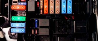
As the electrical diagram shows, the largest number of devices are located in the engine compartment. There is also a circuit board with power safety elements, the number of which is equal to five.
The manufacturer, as expected, placed the mounting block responsible for the functionality of the dashboard in the LADA Granta cabin. It is located at the bottom and has safety elements responsible for the functionality of such receivers:
- external lighting devices;
- power steering;
- electrical components of the interior heating circuit;
- illumination of instruments present on the panel.
The block is equipped with 32 fuses and 12 relays.
The manufacturer also did not forget about the pantographs of the rear of the car, for which he assembled fusible links in a similar block that are responsible for supplying power to the devices, namely:
- rear doors;
- registration number lamps;
- fuel pump;
- rear window heating system.
Replacement features
Briefly about the procedure for replacing the control module on Kalina 2:
- First, the instruments are dismantled from the center console; there is nothing difficult about it.
- Then the lower part of the center console trim is unscrewed, the trim is removed, and you gain access to the fuse and relay box.
- The mounting block with safety devices can be unscrewed, but it cannot be removed because it is connected by wires. You can rotate it a little so that it takes a horizontal position.
- You can stick your hand into the gap formed as a result of turning. Having done this, you will be able to feel the shelf on which the TsBKE is installed. A little to the left there is a bolt with which this module is fixed - you need to unscrew it.
- After this, through the top, through the instrument panel, you will need to disconnect the two connected connectors. After completing these steps, you can carefully dismantle the CBKE and remove it by slightly moving the fuse box. Please note that you should not pull the device too hard, since there are two more connectors on the other side that will need to be disconnected. When the wires are disconnected, the CBKE can be completely dismantled and repaired or replaced.
Photo gallery “Assistance in replacing CBKE”
Price issue
The cost of CBKE will vary depending on the modification. On average, such devices cost from 4,500 to 6,000 rubles.
How to determine the malfunction?
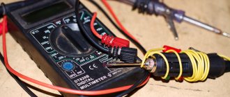
Diagnostics of voltage in electrical wiring is carried out as follows:
- First, you will need a test lamp with wires connected to it. One of them is connected to the negative of the battery or the mass of the vehicle, that is, the body. And the second probe should be connected to the section of the electrical circuit being diagnosed. In this case, it is desirable that the connection point be as close as possible to the battery or safety device.
- If after connection the light starts to light up, this indicates that there is voltage in the circuit. In particular, we are talking about the area between the connection and the battery.
- The remaining components of the electrical circuit are diagnosed in a similar manner. When it happens that the light bulb does not light up and there is no voltage, this indicates that the faulty source is located between this point and the last one where the voltage was. As practice shows, wiring problems are often associated with poor connections, so when problems are detected, the first thing you need to do is check the contacts. Also remember that in some sections of the wiring there is voltage in the circuit only when the ignition key is turned.
An equally important point is to find a short circuit; this problem is relevant for many vehicles, including Grant. One way to find the short circuit point is to dismantle the safety element and then connect a test lamp or tester to its socket. All other components in this circuit must be turned off, that is, there should be no voltage in it. Try moving the wires in different directions, while watching the control - if it starts to burn, then somewhere in the area one of the contacts is closing. Most likely, the reason lies in the rubbing of the insulation (the author of the video is the Kroom&coTV channel).
As for diagnosing grounding reliability, it is carried out as follows:
- First you need to disconnect the battery terminals, then connect one of the probes of the diagnostic tester (multimeter) or a warning lamp to the body of the Lada Granta.
- The second probe should then be connected to the connection or ground point you want to test.
- If, as a result of the connection, the lamp lights up, this indicates that everything is normal with the grounding, you can begin diagnosing other circuits.
And one more point that should be discussed in more detail is diagnosing the integrity of the wiring. This procedure is carried out in order to determine whether there is a break in the wiring or not.
Integrity check is done like this:
- First you need to turn off the voltage from the wiring and diagnose the integrity using a test light and a connected power source.
- Next, you need to connect the wiring from the light source to the ends of the electrical circuit being diagnosed, or one probe to the positive, and the second to the car body. If the control lights up after connection, this will indicate that there are no breaks in the circuit. If the lamp does not light up, then most likely there is a break in the circuit.
- In a similar way, you can check the functionality of the switch by connecting a test lamp to its terminals.
- After the switch is activated, the control should light up.
Video “Independent repair of the control module”
How to properly dismantle the CBKE and how to subsequently repair it - detailed instructions describing all the nuances are presented in the video below (author - MultiAlexander9).
The electrical circuits of modern LADA cars are very different from previous AvtoVAZ models. Some of the relays have disappeared and instead they are replaced by an electrical package control unit (comfort unit), which is responsible for the operation of the ESP, central locking, turn relays, turn signals, etc.). Lada Vesta and XRAY use a similar TsBKE module (central body electronics unit).
Purpose and description
The central body electronics unit (CBEC) came from Renault and is located under the panel behind the glove box. The block is designed to perform the following functions:
- Access control system functions;
- Starter control;
- Control of relays of additional consumers;
- Control of the rear window heater and electric side mirror heaters;
- Windshield defroster control;
- Control of direction indicator and hazard warning lamps;
- Interior lighting control;
- Control of door sill lamps (for the “Lux” package);
- Trunk lighting control;
- Windshield wiper control (for “Classic” and “Comfort” trim levels);
- Energy saving control of vehicle interior lighting devices;
- Monitoring the state of the brake signal switch (BST);
- Monitoring the state of the clutch pedal position signal switch (CPPS) (for configurations with a manual transmission);
- Indication.
CBKE schemes
Electrical connection diagram for TsBKE on LADA VESTA: 2 – rechargeable battery; 3 – starter; 4 – rear left outer lamp; 5 – left headlight; 7 – rear window heating relay (K3); 8 – right headlight; 10 – rear outer right lamp; 13 – trunk light; 15 – fuse 60 A (F70); 16 – additional relay (K8); 17 – ignition switch; 26 – alarm switch; 30 – fuse 5 A (F20); 32 – left steering column switch (light alarm switch); 34 – fuse 60 A (F75); 35 – rear window heater; 44 – windshield heating relay 1 (K21); 46 – windshield heater; 47 – lampshade lighting of the glove box; 48 – switch for the glove compartment lamp; 51 – TsBKE (VSM controller); 58 – fuse 30 A (F61); 59 – left threshold lamp (installed on luxury equipment); 60 – right threshold lighting lamp (installed on the “luxury” configuration); 61 – relay of additional consumers (K2); 63 – fuse 10 A (F32); 84 – fuse 3 A (F43); 87 – left outside mirror; 88 – right outside mirror; 120 – additional starter relay (K23); 134 – brake signal switch; 138 – fuse 5 A (F15); 164 – air conditioner control panel (connection diagram for the “comfort” package); 185 – interior lighting unit with ERA-GLONASS interface module; 196 – fuse 5 A (F24); 200 – fuse 15 A (F11); 201 – fuse 15 A (F12); 202 – fuse 10 A (F13); 203 – fuse 10 A (F14); 204 – fuse 5 A (F17); 205 – fuse 5 A (F16); 229 – fuse 3 A (F49); 230 – clutch pedal position signal switch; 231 – windshield heating relay 2 (K22); 233 – fuse 5 A (F80)
- location of fuses F1-F59 and relays K1-K20 in the interior mounting block;
- location of fuses F60-F80 and relays K21-K28 in the motor mounting block
Basket
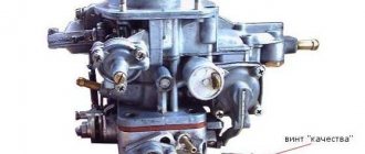
Double-glazed window control unit “Norma” 1118 – 6512010 for VAZ 11183 “Kalina”
©Aktuator On cars of the Kalina family, 2 types of non-interchangeable (by wiring) glass control controller 1118 - 6512010 and 11180 - 3763040 can be installed. 1118 – 6512010 has one 25-pin connection connector, 1118 – 3763040 (1118 – 3763040 – 10) – two connectors.
Read also: How to write in Japanese
Remote control system for double-glazed windows “norm” on a VAZ 11183, Kalina. Controls power windows and central door locking. When the connector is removed, the engine does not start; the device performs some of the anti-theft functions.
Connection
| № | Wire color | Purpose, addressing |
| 1 |
* A regular shock sensor from any alarm system (Alligator, Saturn, Clifford, APS) is suitable.
+ 12 V connect to pin 12; body – on the 6th; We connect the signal wire (a ground appears on it at the moment of activity) to the 1st contact.
During normal arming, Kalina now reacts to an impact on the body (it sounds a horn and blinks turn signals). Similarly, instead of a shock sensor, you can connect a volume sensor (for example, single-level MMS‑1).
You can also connect a pager: + 12 V of the pager transmitter on pin 12, minus on pin 21.
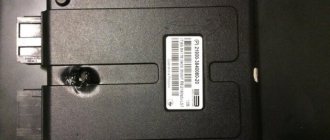
Double-glazed window control unit 1118 – 3763040 (- 10 ) for VAZ 11183 “Kalina”
| External shock or volume sensor input (Not used)* | ||
| 2 | Pink/Black | To the door lock switch in the switch block |
| 3 | Brown/Green | K-Line. To Kl. 71 ECM, Cl. 18 APS‑6 |
| 4 | Brown | Connects to ground when the driver's door is closed |
| 5 | Grey | To rear window heating element |
| 6 | Black | Weight |
| 7 | Pink/White | To the door lock switch in the switch block |
| 8 | Yellow/Blue | In the instrument cluster, to the APS-6 indicator |
| 9 | Black/White | Connects to ground when opening the hood. C VK engine compartment lamp |
| 10 | Two White/Red | Connects to ground when opening the rear doors |
| 11 | Brown/Red | Connects to ground when opening the right front door |
| 12 | Output 12 V power supply for external sensor (Not used)* | |
| 13 | Not used | |
| 14 | Yellow | Pulse + 12 V, closing all doors and trunk |
| 15 | Red/Blue | To class 14 APS‑6 |
| 16 | Blue with Black | To the left direction indicator |
| 17 | Red/Blue | Impulse + 12 V, opening passenger doors |
| 18 | Red/Black | Pulse + 12 V, driver's door opening |
| 19 | Pink/Red | Impulse + 12 V, opening the trunk lock |
| 20 | Yellow/Blue | To terminal “15”, through fuse F 9, in the mounting block |
| 21 | Grey/Black | "-" Horn relay |
| 22 | White/Blue | Connects to ground when the driver's door is opened |
| 23 | Red | To permanent plus through fuse F 5, in the mounting block |
| 24 | Blue | To the right turn signal |
| 25 | White black | Connects to ground when opening the trunk |
| Controller board | ||
| Controller board |
Sign
| Possible reasons | Elimination method |
| The key code is not readable |
1 . 1 Malfunction in the VZ communication coil circuit
1 . 2 Malfunction in the circuit from the block to the communication coil to the APS ECU
1 . 3 Transponder missing in OK
1 . 4 The transponder in OK is faulty (detected during pre-production preparation)
1 . 5 The transponder in the Republic of Kazakhstan is faulty (detected during pre-production preparation)
1 . 6 Malfunction of the input transponder circuit in the APS ECU
1 . 8 The communication coil came off from the VZ pad on the inside
Read also: Inexpensive used jeeps and crossovers
2. 2 Malfunction of W‑Line circuits in the APS or ICS units
2. 3 Lack of supply voltage on the APS or KSUD unit
2. 4 The “Normal” electrical package is faulty (the control driver has burned out)
2. 5 KSUD does not contact
| 1 . 1 - replacement 1118 – 6105006 (set) - rearrange the transponder - rearrange the remote control 1. 2 - replacing the instrument panel harness 1. 3 -replacement of KSUD -replacement of 1118 – 6105006 (set) -replacement of remote control -train the system 1. 4 - rearrange the transponder (if there is a clean one) otherwise: - replace 1118 – 6105006 (set) - retrain the system 1. 5 - replace the remote control - train the system 1. 6 - replace the faulty unit - train the system 1. 7 - replace the remote control with a “clean” one - train the system 1. 8 - replace 1118 – 6105006 (set) - rearrange the transponder - rearrange the remote control | ||||
| 2. 1 W‑Line communication line break | 2. 1 - restore the circuit between unit No. 18 of the APS ECU and unit No. 71 of the KSUD 2. 2 - replace the faulty unit - train the system 2. 3 - eliminate the cause 2. 4 - replace the electrical package - retrain the system 2. 5 - eliminate the leak - replace the control valve - retrain the system | |||
| The read key code is not in the APS memory | 3. 1 - retrain the system 3. 2 - replace the KSUD - replace 1118 – 6105006 (set) - replace the remote control - train the system | |||
| The read key code is not in memory | Revealed during pre-production preparation | 4 beeps IC flashes | The KSUD was previously trained with a different system | — train the system |
| The system is not trained | Security function with remote control on/off, but the internal combustion engine can be started with any mechanical sting (the immobilization function does not work) |
|