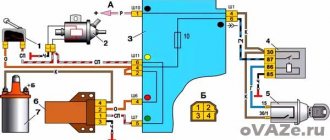
Scheme for connecting the alarm system to the Central Lock on a Priora
This diagram is the simplest diagram for connecting an alarm system to a standard Priora Central Lock.
To implement this scheme, we lay two wires in the driver's door and connect them to the gap in the brown wire between the electric drive and the driver's door module.
When connecting the central locking according to this scheme, all doors will close, and only the driver’s door will open, the rest are opened by a button in the driver’s door.
If the standard alarm is activated, you can reprogram it so that all doors are opened simultaneously using the alarm key fob. To do this, with the ignition on, press both buttons on the key simultaneously until the signal sounds. One signal enables this function, two signals disable it.
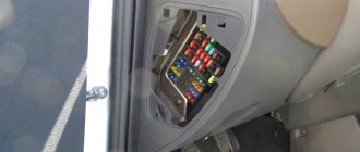
The alarm connection points for Priora are located here.
Many car owners prefer to install security equipment on their own. For self-installation, you need to determine the alarm connection points on the Priora, and then connect the cables with subsequent insulation of the joints.
Why does the central locking system not work?
Quite often a situation arises when the central lock cannot be opened with a key or key fob. As a rule, the problem here is solely due to a faulty relay or due to damaged wiring.
If the key normally opens the central locking system, but the key fob does not, then most likely the battery in the latter is simply dead or its button needs to be cleaned. Experienced specialists note that in their practice, signal receiver or transmitter failures have occurred extremely rarely. You can check it simply - just use a spare remote control or insert a new power supply into the existing one.
The inability to open with the key is due to incorrect operation of the activator. This device is located directly in the driver's door, and it is responsible for distributing the signal through the locking mechanism. First of all, in this case, check:
- wiring;
- circuit breakers;
- terminals.
Two schemes (simple and complex)
First of all, before connecting the alarm, you need to study the instructions included with it. The main unit always has relays installed: one of them closes when the locks are locked, the second acts on opening. The connector to which the relay contacts are connected usually has 6 pins. There is nothing complicated here.
In the first case, we will use only this connector. The second circuit uses another contact, called “signal output for 2-step lock opening”. Find it on the main unit.
We connect the alarm in a simple way
A push-button module is installed in the driver's door of the Lada Priora. The door trim must be removed and the connector for this module must be found:
We will need a brown cord from the connector. It is a signal, and the alarm relay is connected to its break:
What does the standard Priora alarm system consist of?
Any standard anti-theft system consists of several elements, it includes:
- training key;
- key fob;
- signal receiver antenna;
- APS block;
- lock activators;
- sound signal;
- EEPROM section in the ECU.
Training key (transponder)
The key set includes two ignition keys. One of them is the so-called educational one. It has a built-in special semiconductor chip with characteristic magnetic radiation. It is inserted into a special recess in the end part of the key, closed with a red decorative cover. Because of this, such a key is sometimes called a red key. This element is necessary to activate the standard anti-theft system. And for using the car if the anti-theft is not activated.
Key fob
This ignition switch has a key fob built into the handle for a standard alarm, just like a regular car alarm. It has only three buttons:
Accordingly, when the APS is activated, each button performs its own function.
Connection points
Power is supplied to the security system from the ignition switch; the negative terminal is attached to a metal element connected to the car body. To operate the remote engine start unit, you need to use the cable coming from the limit switch under the parking brake lever. Information about the operation of the motor is transmitted to the head unit via a separate cord connected to the speed sensor.
Lada Priora alarm connection points include cables going to switches mounted in the doors, under the lids of the luggage compartment and the power unit compartment. Additionally, the wires of the original siren (or an alternative unit) are connected. If the alarm system supports switching of the CAN-LIN digital bus, then it is also necessary to connect the points (in accordance with the factory documentation).
- Repair of door locks for VAZ 2108, VAZ 2109, VAZ 21099 cars
Connecting the central lock
To connect the alarm system to the Priora central locking system, a cord is used that goes to the control controller. The cable is covered with brown insulation. With a direct switching scheme, all door locks are locked simultaneously, but when the security is disarmed, only the driver's door will open. If the car owner wants to open other doors based on a signal from the remote control, then a 2-stage shutdown scheme is implemented.
The car owner connects an additional relay to the circuit, which operates in parallel with the contact units for blocking the power windows of the doors. If you do not install a window drive relay, then when a signal is sent to the central locking system, the motors will briefly operate (to lower or raise the windows). This occurs due to the design features of the electrical wiring harnesses and electrical components installed in the doors of Priora vehicles. Some cars use 1 relay (in the absence of rear electrical mechanisms).
Priora central locking malfunction.
The Priora central locking may have some malfunctions for which there are many reasons. They are mainly associated with a malfunction of the keys, the electrical package control controller, the Priora immobilizer, the driver's door unit, a break or short to ground in the connecting wires or the CAN bus. If a malfunction occurs and it is possible, pay attention to the operation of the power windows and the ability to adjust the mirrors. If they also do not work, then the signal wire from pin 5 of the driver's door module connector and pin 5 of block X3 of the electrical package control controller may be faulty.
Central locking malfunctions often include immobilizer malfunctions, since they are closely related. The immobilizer flashing and beeping may indicate a malfunction.
Below is a diagram of the connection of the Priora central lock.
| Remove the driver's door trim. | |
| We disconnect the block going to the actuator from the power window control unit and unscrew the two self-tapping screws securing the actuator. | |
| Unscrew the two bolts securing the door lock and remove it. | |
| Now the internal drive of the lock has become more mobile. We release the drive down a little and align the last self-tapping screw for fastening the actuator with the hole in the door. We unscrew the screw, remove the actuator from the linkage hook and take it out. | |
| We install the new actuator in the reverse order. We connect the power window control unit and check the operation. | |
| We install a lock on the door. | |
| We install the door trim in place. |
Notes on implementation of schemes
Let us immediately note: if there are no window lifters, the second diagram will not contain parts K2/K3. Then you only need to cut one wire. Sometimes only the rear windows are missing. This means that relay K3 is excluded. And the diodes connected in parallel with the winding can be absolutely anything.
Now we list the requirements for an element called “relay”:
- Operation voltage - 12 Volts;
- Switching current - 10 A or higher;
- The current consumed by all relay windings should not exceed the value specified in the instructions for the signaling. Usually it is 200-300 mA.
It is the last requirement that is often violated.
In order for “scheme 2” to work, it is necessary not only to assemble it, but also to program the main unit: you need to enable the “2-step unlocking” option. And be that as it may, control impulses cannot be made too long. Use values of 0.7-1.1 seconds.
Connecting limit switches
The signal cables from the limit switches are connected to the electrical control unit, which is located inside the car. From the front doors there are cables with blue-black and brown insulation; wires with gray-red protection are laid to the rear elements. An additional yellow-red cord is routed to the luggage compartment lid lock. The engine compartment hood switch is covered with white and black insulator. Before starting the connection, it is recommended to check the purpose of the cables according to the electrical diagram of the machine.
Installation and connection instructions
Installing an alarm system on a Priora begins with determining the locations of the security complex blocks. During installation, it is necessary to ensure a minimum length of connecting cables; it is prohibited to place modules on standard electrical appliances. Some Lada 2 Priora cars use a factory security system with a control panel located on the head of the key. The standard alarm unit on the Priora is located in the car's interior under the lining of the floor tunnel. When installing additional protective equipment, the standard device is disabled.
Do-it-yourself alarm installation begins with the installation of the head unit, which is located inside the instrument panel. The unit is located at a distance from the cabin heater; it is recommended to tilt the module with the plug down to drain the condensate. The positive power pulse comes from the ignition switch; a fuse is provided in the circuit (the rating is indicated in the documentation included with the car alarm).
The antenna unit is placed on the windshield; some alarm systems allow for discreet placement of the unit (with a reduction in the range of the remote control).
To improve the quality of the communication channel, it is recommended to lay the connecting cable at a distance from the factory electrical wiring.
When using equipment with autostart, it is necessary to install a temperature sensor in the engine compartment; On some alarm models, a separate relay block is used, which ensures starting the motor from a distance.
The shock sensor is located inside the car (piezoelectric microphone) or inside the head unit (3-axis acceleration sensor). When installing equipment, it is necessary to display a control LED on the rack casing, as well as a programming switch. The head wiring harness is connected to the central locking unit and siren located in the engine compartment. An additional alarm channel is used to control the trunk lid lock. Connections are made in accordance with the factory instructions.
- Why the central locking on the VAZ-2112 does not work: the main reasons
Circuit breakers
Fuse box of Lada Priora under the hood
F1 (green) 30 Electronic engine management system F2 (blue) 60 power package control unit, engine fan, heated rear window, ignition switch relief relay F3 (blue) 60 cooling fan power supply circuit, horn, alarm, ignition switch, combination devices, interior lighting, brake light, cigarette lighter F4 (blue) 60 Generator Priors F5 (red) 50 Electromechanical power steering F6 (blue) 60 Generator
Fuse box of Lada Priora in the cabin
F1 (blue) 15 Main relay and starter interlock circuit F2 (brown) 7.5 Controller power circuit F3 (blue) 15 Electric fuel pump fuse K1 - Ignition relay K2 - Electric fuel pump relay
Lada Priora fuse box under the instrument panel
F1 25 Electric radiator fan of the cooling system F2 25 Heated rear window Priors F3 10 High beam right F4 10 High beam left F5 10 Sound signal F6 7.5 Low beam (left) F7 7.5 Low beam (right) F8 10 Alarm signal F9 25 Heater Priors F10) 7.5 Interior lighting, instrument cluster, brake light F11 20 Windshield wiper F12 10 Terminal 15 devices F13 15 Cigarette lighter F14 5 Left side light, license plate light, trunk light F15 5 Right side light F16 10 Terminal 15 ABS F17 10 Fog light (PTF) left F18 10 Fog light (PTF) right F19 15 Heated seats F31 or F27 30 Electrical package control unit
Characteristics and principle of operation of the blocker on Priora
Priors can use two types of immo - APS-4 and APS-6. The first ones began to be installed on VAZs back in the early 00s and are considered less reliable.
In the blocking device on Priora, the main role is played by the PIC16С65В controller and the K-Line bus. And the main element of the microprocessor module for working with the blocker is the physical section EPROOM. The latter records a special file with the same name, contained in the memory of the ECU (electronic control unit). It stores immobilizer learning combinations and it is this element that is responsible for the safety of the vehicle. If the file is activated and the blocker does not send a signal, the microprocessor module opens the ignition circuit and turns off the fuel supply system.
In more detail it looks like this:
- The driver, approaching the car, presses a button on the remote control.
- The doors open and the key is inserted into the ignition.
- A signal comes from the chip and is fed to the antenna adapter.
- The ring-type antenna begins to read the pulse from the chip. This element is made of a large number of turns of copper wire. The antenna adapter itself is located around the ignition switch cylinder.
- The pulse, after reading, is transmitted to the microprocessor module. The control unit begins diagnosing the signal and compares it with the normalized one. As a result, it gives a command to allow or prohibit the start of the power unit.
- If the key is not recognized and the device begins to block the main components, then an indicator is displayed on the control panel indicating a faulty immobilizer.
Auto electrician Sergei Zaitsev spoke about the principle of operation of the standard anti-theft system.
Where is the immobilizer located?
In the first models of vehicles with security devices, the immobilizer unit was located separately. But in Priors it is installed in the electrical package. The device is mounted in the car radio compartment, slightly below the central part of the console in the cabin. The microprocessor module is also located here.
The procedure for activating the immobilizer.
To activate the Priora immobilizer, you must turn on the ignition with the red training key and after 6 seconds turn it off and remove the key from the lock. In this case, the immobilizer indicator will start flashing at a frequency of 5 times per second. This blinking frequency must continue throughout the activation period. Change means stopping the process due to incorrect actions.
While the indicator is flashing, you must insert it into the lock and turn on the ignition with the main key. If the action is correct, three beeps will sound from the buzzer. Do not turn off the ignition until two more beeps sound. After this, you can turn off the ignition and remove the key from the lock.
If you need to learn another key, then it must also be inserted into the lock and repeat the action as with the first key. To exit the learning mode, you must insert the learning key into the ignition switch. The Priora immobilizer buzzer will give three sound signals, and after about 6 seconds two more. After this, you must turn off the ignition without removing the key from the lock. After 10 seconds, a single beep will sound and the LED will flash as normal. This indicates the end of the procedure.
Lada Priora alarm connection points.
| Chain | Wire color | Polarity | Location |
| Weight | M6 nut near the mounting block | — | |
| Food +12 | Brown | + | Ignition switch |
| Ignition | Blue with black | + | |
| Starter | Red | + | |
| Nutrition +12 (second option) | Red | + | BUS, connector X1 |
| Turns | Blue | + | |
| Turns | Blue with black stripe | + | |
| Ignition (second option) | Orange | + | BUS, connector X2 |
| Hood switch | White with black stripe | — | |
| Driver's door - limit switch | Blue with black stripe | — | BUS, connector X3 |
| Passenger door - limit switch | Brown | — | |
| Rear door - limit switch | Gray with orange stripe | — | |
| All doors (with interior lighting delay) | White with black stripe | — | |
| Trunk - trailer | Yellow with red stripe | — | |
| Opening the trunk | Blue with red stripe | — | |
| Ts.Z. (open) | According to the diagram below | ||
| Ts.Z. (close) | |||
| Handbrake (via diode) | Brown with blue stripe | — | Dashboard |
| Generator | Brown with white stripe | + | |
| Tachometer | Brown with red stripe | + | |
| Can tire High (since 2013) | Yellow-red | Diagnostic connector | |
| Can tire low (since 2013) | Grey | ||
| LIN bus (since 2013) | Blue-white | Driver's door harness |
Priora controller connector: how to properly connect the alarm system
Installation of the security system is quite simple and the primary connection points for the Priora alarm system are located on the controller connectors. First of all, connection is made to X1: 12V power supply to the red wire (numbers 2,3), turn signals are connected to the blue and blue with a black stripe wire (pins 14 and 15).
This connection stage is responsible for the normal functioning of the turn signals during alarm installation. And in addition, they will guarantee the correct operation of this part of the car’s electronics.
Next, work is done with connector X2, to which the wires from the ignition and hood will be supplied and connected. To connect the ignition, you will need to connect the orange wire (numbered 9) to the connector. A white wire with a black stripe (pin 17) is connected from the hood. This work is carried out for the following cases:
1. Preventing an attacker from trying to open the hood.
2. Prevent attempts to damage or remove the battery.
3. Normalization of autorun operation.
4. Correct functioning of the protection system.
The next step will be for Priora to connect the connection points on the last X3 connector. The work is quite simple and consists of connecting the wires leading to the limit switches. For the front doors, you will need to connect the brown wire (pin 7) for the passenger door and the blue/black wire (pin 6) for the driver's door to the connector.
Next, connect the yellow wire with a red stripe (pin
from the trunk and a gray wire with a red stripe (pin 1) for the rear doors.
Preparing for self-installation of central locking
The complexity of installation directly depends on the brand of car. But, in fact, cases when something needs to be filed and drilled out for a long time are rare. These mainly include long-lived cars, which are at least thirty years old. In most options, the car is already prepared for installation of the central locking system. All that remains is to put the kit in place. Well, the second side of the issue is the set itself. If you don’t want to dig around for a long time, buy universal locks. Installation is simple and you will find plenty of information on them.
What's in the basic kit?
We take the simplest universal kit. Control, in our case, will be carried out from a special key fob. Usually there are two. There is an option when the system will be activated by turning the key in the driver's door lock. You can also display a special button in the car interior. This additional option is very nice if you need to lock the doors while driving. It is not always convenient to use the control panel.
So, we purchase a universal lock kit, which in most cases includes:
- Four motors. They will be attached to the door. One of them with four wires is on the driver's door;
- Control block. We will subsequently connect all the wires to it;
- A set of wires of the required length. If you feel that there are not enough of them, buy additional ones immediately;
- Key rings, strips, screws, etc.
central locking
Necessary tools for work
Now we are assembling a tool that will be useful to us in our work. If there are no holes for mounting motors in the doors, then prepare a drill with a drill bit. Also needed: screwdrivers, a screwdriver, a knife, corrugated tubes (wires are laid through them to avoid chafing and the influence of external factors on the wiring) and electrical tape. We will rewind all exposed sections of wires with tape in order to avoid their contact with metal parts of the body.
The last thing to do before proceeding with installation is to remove the trim and dust curtains from all doors. Determine the location where you will mount the mechanism so that it does not interfere with the operation of the window regulators. If necessary, you will have to make an additional bracket.
Installation of central locking
All necessary preparations have been made, and you can begin to work. We attach the motors to the doors, remembering that we place the motor with four wires on the driver's door. We also install the control unit there.
Connection diagram
After installation, we check the correct interaction with the lock rod, which is responsible for opening and closing the door, and the smooth operation of the lock itself.
Let's move on to the wires. We pull them from each motor to the control unit. Think in advance about how to pull the wire from the rear right door. You can use the space under the seats. We connect them according to the circuit and perform the test. To do this, return the battery to its previous state. If you find any faults, first check that the connections are correct. The plus and minus outputs may be confused. When checking, it is better to be inside the car or not to close the doors. Once you restore battery function, the locks should work automatically.
Installed and connected motor
If you still want to make a lock control button, prepare the missing parts in advance. Additional wire and button. It can be embedded into the dashboard. Buy any button, for example, for a window regulator.
Installation of the central locking control button
We look for the black, brown and white wires under the side panel and connect to them. Alternatively, you can stretch the wires and connect to the electrical bundle from the central locking of the driver's door. And we carry out the rest of the connection according to the diagram.
Connection diagram for the central locking control button
Connection diagram for the central locking control button
It is absolutely not necessary to make this button on the panel. Again, it all depends on convenience. You can place it in the space between the front seats if the necessary electrics are there. Alternatively, the button can be embedded in the armrests on the doors.
The trunk can also be connected to the central locking. Which, by the way, will also significantly save your time and nerves. If you have a wiper on the rear window, then the necessary electrical wiring is already installed, and connecting will not be difficult. The main thing is not to forget that central locking still cannot secure your car one hundred percent. Such options must be used comprehensively and, of course, an alarm system must be installed.
Determining malfunctions of the central locking
Failure of the central locking system cannot occur spontaneously. There are harbingers indicating that the system is not working correctly or malfunctioning. They cannot be ignored. It is necessary to determine the cause of the malfunction as quickly as possible.
Reasons for failure of the car's central locking system:
1. Complete refusal.
Does not respond to pressing buttons on the key fob sending commands to the central control unit. Often the cause of the malfunction is trivial. A discharged key fob battery prevents sending a command to open or close locking devices.
2. Partial refusal.
It is characterized by alternating periods of normal operation in normal mode and a complete refusal to respond to remote control commands.
3. Malfunction of locks.
The malfunction manifests itself as chaotic operation of the locks. They can randomly close, open or be completely blocked without responding to incoming commands. The malfunction is dangerous because the doors can be completely blocked without the possibility of mechanical opening. You have to remove the door trim and open it manually.
Before you begin repairing the central locking system, you must determine the cause of the malfunction.
1. Alarm testing.
If the central locking is combined with an alarm system, it is necessary to inspect it first. The door locking devices do not respond to signals from the control panel; they must be checked mechanically using the ignition key.
If the central locking operates in manual mode, you need to check the electrical and control circuits of the alarm. One of the common options is that the battery in the key fob may have run out.
2. The central locking does not work completely or partially.
When testing the central locking system, it refuses to work or operates irregularly in manual mechanical mode using the ignition key. It is necessary to clarify the nature of the manifestation of the malfunction.
If there is a complete system failure on the vacuum central locking system, the compressor operation cannot be heard. The electric central locking responds with weak, barely audible clicks of the operating relay. The locking device buttons remain stationary.
It is necessary to locate the central locking circuit fuse. If it is burnt out, replacing it will solve the problem of mechanism failure. Depending on the car model, there may be more than one fuse.
3. The system fuses are intact and undamaged.
If it is determined that the fuses are safe and sound, you must continue to persistently examine the system to determine the cause of the malfunction.
The driver's door drive cannot transmit the signal received by it from the control panel to the other doors. Similar symptoms appear when the driver's door actuator limit switch is faulty. The control signal is not detected.
Repair work on the central system must begin with checking the power supply and control signal. It is necessary to visually check the system wires for damage. The limit switch must be checked. It is installed inside the drive.
4. Arbitrary opening or closing of door locks.
Often, after pressing the key fob button, the door locks close and after a few seconds randomly open. The opposite sign of a malfunction also appears when the locks close without giving a signal.
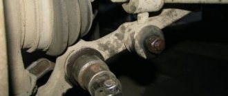
The cause of the malfunction is a violation of the fixation of the rod fasteners. Located between the drive and the driver's door lock mechanism. There is a violation of the process of unlocking and locking doors.
Features of connecting the alarm to the lock on the driver's door
Installing a central lock on the driver's door allows the owner to avoid the main reason for car theft: opening one of the passenger doors. That is why you should carefully study the car alarm connection points on the Priora in order to ensure maximum protection and ease of use of the vehicle.
For the central locking to function, you will need to connect two wires to the driver's door. They should be triggered by a break in the brown wire when the lock is closed and, accordingly, the locking buttons are activated.
For the modern Lada Priora, the alarm connection points responsible for the normal operation of the autostart are also very important. You will need to connect a brown wire with a red streak to the dashboard connector. And the brown/white wire is connected to the generator. All this allows you to control the autostart procedure. The last connection point will be the brown/blue wire from the handbrake.
Upon completion of the full procedure for searching for points and connecting the corresponding wires to them, you need to visually evaluate the connections and check the operation of the alarm in action. Until the moment of complete reliability in the correct functioning, the Lada Priora alarm connection points must remain open.
This will allow you to immediately begin correcting them if any problems are detected. Once the goal is achieved, the plastic of the front panel and tunnels can be replaced.
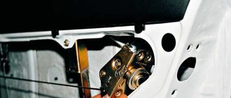
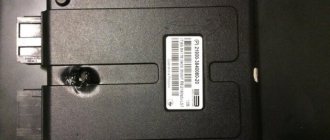
The driver's door central locking actuator on the Priora has failed. We need to change it.
I purchased a gear motor for the electric lock of the driver's door lock (4 wires) on a Priora in the store.
Article: 2170-6512110-10. Price 350 RUR
This is the culprit. Served for 4 years.
I'll take it apart later and post a photo report.
Tags: replacing the central locking actuator on a Priora, standard central locking actuator on a Priora, electric door lock motor gearbox on a Priora
To add comments you must log in or register on the site
- Lock, drive rods and rear door handles
- 1 – outer handle rod
- 2 – external handle
- 3 – intermediate locking rod
- 4 – intermediate locking lever
- 5 – lock lock button rod
- 6 – internal handle
- 7 – pull of the internal handle
- 8 – internal lock
- 9 – external lock
- 10 – external lock escutcheon
Lock, drive rods and rear door handles.
You will need: an “8” wrench, flat-blade and Phillips-blade screwdrivers, and pliers.
- 1. Disconnect the wire from the negative terminal of the Lada Priora battery.
- 2. Remove the rear door trim of the VAZ 2170 (see “Removing and installing the rear door trim”).
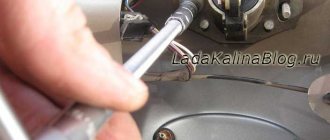
3. Squeeze the pad retainer...
4. ...and disconnect the wiring harness block of the door lock gearmotor.
5. Unscrew the three screws securing the inner handle.
6. Move the handle away from the interior door panel of the Lada Priora.
7. Tighten the drive rod end clamp...
8. ...and disconnect the rod end from the inner handle of the VAZ 2171 lock.
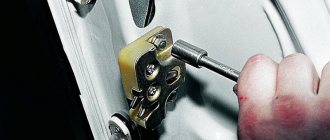
9. Using a screwdriver, remove the lock lock intermediate rod holder from the door.
10. Unscrew the screw securing the intermediate locking lever.
11. Lower the intermediate lever down and remove the lock lock button rod from the bracket hole.
12. Remove the bolt securing the glass guide...
13. ...and remove the guide
14. Use a screwdriver to pry the end of the rod of the outer handle of the VAZ 2172 and disconnect the rod.
15. Remove the cover.
16. Remove the two mounting screws...
17. ...and pull out the lock.
18. screw securing the internal lock.
- 19. ...and remove the internal lock with locking rods and internal handle.
- 20. Install the lock in the reverse order of removal, having first lubricated all rubbing parts with grease. Check the ease of opening and the reliability of closing the door lock. If necessary, adjust the lock in the same way as adjusting the front door lock (see “Adjusting the front door lock of the Lada Priora”).
Why is everything so difficult?
It would seem that we only need to manage the locks. Why then connect to the window lift motors?
All relays operate simultaneously
The opening of the passenger doors is carried out by the second impulse (relay K1 is activated). And elements K2 and K3 at this moment block the power windows. If they are not blocked, the windows in the doors will lower during the entire control pulse. And even in 0.8 seconds they will open noticeably.
Of course, connecting the signaling system in a Priora is more difficult than in many domestic cars. At the same time, the “Grant” in the “Norma” configuration uses a similar scheme. Be that as it may, the Lada Priora is the flagship of VAZ. And probably, difficulties with the electrical part should not confuse a competent car owner. It is also known that the standard control unit can be reprogrammed, and then unlocking occurs in one step. In this case, the connection is made according to “Scheme 1”.