Mounting block
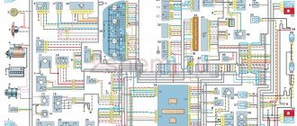
Lada Vesta fuse diagram
Interior mounting block
Schematic location of fuses
Body connector
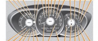
Layout of buttons on the steering wheel
Lada Vesta is equipped with many electrical appliances, each of which is vulnerable to voltage surges. To protect consumers, there is a fuse in the circuit of each of them, and if for some reason it blows, it will have to be replaced, otherwise the electrical appliance will not work. Just first you need to find the Lada Vesta fuse box.
Why are fuses needed?
Fuses are elements of an electrical circuit that protect devices from voltage surges. They consist of a plastic case, two contacts and a working element.
The principle of their operation is simple: each element has an operating voltage, and if this value is exceeded, it will immediately burn out and the circuit will open. In fact, the protective component takes the blow, protecting electrical appliances from damage. Its purchase is much cheaper than replacing one or more consumers, which, among other things, can affect the control of the car.
Interesting!
The cigarette lighter in Lada Vesta has a fuse that blows more often than others. Usually the reason for this is connecting devices with high current consumption or several devices at once through a tee.
Description of fuses on a Lada Vesta car: location, diagram, price
Lada Vesta cars are equipped with knife-type modules in the following modifications:
- Mini;
- JCase
The manufacturer abandoned the installation of cylindrical modules 7 years ago due to the obsolescence of the model.
Relay-breaker layout diagram
| Designations | Who is responsible for what/what provides |
| K 1 | Lighting, seat heating |
| K2 | Responsible for the cigarette lighter |
| K 3 | Heated rear window |
| K 4 | Front windows |
| K5 | Interior heater (stove) |
| K 6 | Window lifter for rear doors |
| K 7 | Gasoline pump |
| K 8 | Car socket (powered by 12 Volts) |
| K9 | Heated windshield |
| K 10 | Heating relay |
| K11 | Starter |
| K 12 | Sound signal |
| K 13 | Beep (optional) |
| K 14 | Relay KSUD |
| K 15 | Air conditioning system |
| K 16 | Compressor clutch |
| K 17 | Cooling fan |
Lada Vesta fuse installation diagram
| Marking/amperage | What he is responsible for (with description) |
| F (F-1) / 20 | Windshield washer |
| F (F-2) / 5 | Understeering's shifter |
| F (F-3) / 10 | High beam (left headlight) |
| F (F-4) / 10 | Steering column switch (left) |
| F (F-5) / 20 | Heated seats |
| F (F-6) / 30 | Side lights (right) |
| F (F-7) / 30 | Left dimensions |
| F (F-8) / 7.5 | Rear fog lights |
| F (F-9) / 10 | Right turn signal repeaters |
| F (F-10) / 10 | Automated gearbox selector |
| F (F-11) / 10 | Low beam (left side) |
| F (F-12) / 10 | Direction indicators |
| F (F-13) / 30 | Power circuit |
| F (F-14) / 30 | Stop signals |
| F (F-15) / 10 | Rain sensor, external lighting, hydraulic headlight range control |
| F (F-16) / 15 | Stop light (optional) |
| F (F-17) / 15 | Illumination of the glove box, thresholds |
| F (F-18) / 10 | Turn signal repeaters (left) |
| F (F-19) / 10 | Low beam (right) |
| F (F-20) / 10 | Heated mirrors (external) |
| F (F-21) / 5 | Instrument panel (panel) |
| F (F-22) / 5 | —/— |
| F (F-23) / 5 | —/— |
| F (F-24) / 5 | ERA GLONASS |
| F (F-25) / 5 | ES9.1 controller |
| F (F-26) / 5 | Gasoline pump |
| F (F-27) / 20 | Parktronic |
| F (F-28) / 15 | Electric power steering |
| F (F-29) / 15 | Line output to tow hitch |
| F (F-30) / 20 | ERA GLONASS (optional) |
| F (F-31) / 15 | ERA GLONASS (optional) |
| F (F-32) / 15 | Engine compartment lighting |
| F (F-33) / 5 | Window lifters |
| F (F-34) / 15 | Steering wheel rotation sensor |
| F (F-35) / 5 | Door program block |
| F (F-36) / 15 | Radio, diagnostic connector |
| F (F-37) / 15 | Stop light (optional) |
| F (F-38) / 15 | Stop light (optional) |
| F (F-39) / 15 | Daytime Running Lights |
| F (F-40) / 20 | High beam (right) |
| F (F-41) / 20 | Standard cigarette lighter |
| F (F-42) / 20 | Bus power |
| F (F-43) / 20 | Door locks |
| F (F-44) / 20 | Window lifters |
| F (F-45) / 20 | Heater fan (interior) |
| F (F-46) / 20 | Windshield wiper (windshield wipers) |
| F (F-47) / 15 | PDS, LBS, LGO |
| F (F-48) / 15 | Windshield wiper (optional) |
| F (F-49) / 15 | PTF, ZPTO, license plate |
| F (F-50) / 15 | PDS, LBS, LGO (optional) |
| F (F-51) / 70 | Electric power steering |
| F (F-52) / 30 | Heated rear window |
| F (F-53) / 40 | Stability Program (ESP) |
| F (F-54) / 15 | Air conditioning system |
| F (F-55) / 5 | Reservation |
| F (F-56) / 15 | Automatic transmission |
| F (F-57) / 15 | Reservation |
| F (F-58) / 70 | Transmission optional |
| F (F-59) / 15 | Air conditioner |
| F (F-60) / 15 | Fuse supply circuit |
| F (F-61) / 60 | Generator |
| F (F-62) / 10 | Beep (optional) |
| F (F-63) / 5 | Reversing light |
| F (F-64) / 15 | Anti-theft alarm |
| F (F-65) / 15 | central locking |
| F (F-66) / 20 | Canister, air flow sensor, timing valve |
| F (F-67) / 15 | Fuel pump, charging |
| F (F-68) / 15 | Reservation |
Causes of fuse failure
- Failure to comply with the scheduled technical inspection schedule;
- Installation of non-original spare parts;
- Unprofessional installation;
- Mechanical damage to adjacent mechanisms and units;
- Short circuit in the wiring;
- Damage to the insulating layer;
- Oxidation of contacts;
- Loose fixation of terminal blocks;
- Condensation formation, moisture penetration into the structure.
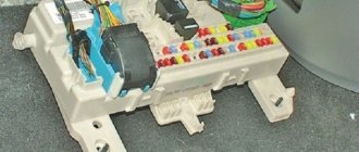
Lada Vesta fuse box with description (engine compartment
The required box is located above the battery, on the right side of the air filter. On the cover of the unit you can see warning signs in the form of a crossed out figure of a man with a hose and a lightning bolt.
To remove the cover, bend the two latches at the top and bottom. Be careful because... they are very fragile.
Schematic layout
The contents of this mounting block are as follows:
Mounting block
The current limit (amps) is indicated on each component. The Lada Vesta fuse diagram under the hood looks like this:
Lada Vesta fuse diagram
Which circuit each fuse belongs to and which consumer it is responsible for can be found in the table below.
Fuse Circuit Chart Fuse Chart Note: Depending on the configuration, some items may not be present.
Table with the designations of the relays that are present in the engine compartment block:
Relay designation table
Where are the fuses and block on the Lada Vesta?
The fuse and relay box is scattered in two places.
Relay and fuse box under the hood
The location is standard. It is located next to the expansion tank and is closed with a lid. There are tweezers inside for removing fuses.
Fuse box in the passenger compartment
Located to the left of the steering column. Closed with a lid with clips.
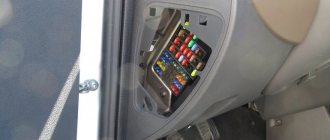
Lada Vesta fuse box with description (interior)
This mounting block is located in a place familiar to drivers - near the left foot. Actually, the space around the trunk opening button and the headlight adjustment control is the cover of the mounting block.
First, remove the plastic clips (nails) that secure the cover to the upholstery. One of them is located on the side of the ignition switch, the other is in the lower left part of the cover (may be absent on some cars). Next, turn the 3 plastic handles at the bottom and pull the lid, releasing all the holders.
Schematic layout
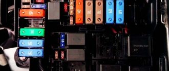
In the interior mounting block you will see the following picture:
Interior mounting block
On a note!
In the lower right corner there are spare fuses for the Lada Vesta.
Schematically the block looks like this:
Schematic arrangement of fuses It is deciphered as follows: Explanation of spare fuses Explanation of spare fuses Explanation of spare fuses Explanation of spare fuses Explanation of spare fuses Relays that are present in the cabin: Designations of the snout in the cabin Body connector Diagram of the buttons on the steering wheel
Mounting block Lada Vesta in the car interior
The mounting block is located in a familiar place - near the driver’s left foot. To access the relays and fuses:
- turn the plastic handles (3 pieces) holding the unit cover from below;
- remove the lock on the upper right side of the cover;
- Pull the bottom of the cover, disconnect its upper holders to the instrument panel and remove the unit cover.
Fuse diagram (Fuse, Rating, Circuit, Purpose, Fuse type)
- F1 15A K15R Windshield washer mini
- F2 30A*1/5A*2 K15R Left steering column switch (not luxury/lux) mini
- F3 10A*1 Left high beam headlight (not luxury) mini
- F4 30A*1/5A*2 K30S Left steering column switch (not luxury/lux) mini
- F5 15A K15R Heated seats mini
- F6 7.5A*1 K30S Right side lights mini
- F7 10A*1 K30S Left side lights mini
- F8 5A*1 K30S Rear fog lights mini
- F9 3A Direction indicator (turn signals) in the right mini mirror
- F10 5A K15S AMT mini robotic gearbox selector
- F11 10A*1 Left low beam headlight (not luxury) mini
- F12 15A K30S BCM controller (turn signals) mini
- F13 10A K30S BCM controller (own power supply) mini
- F14 10A K30S Mini brake pedal switch off
- F15 5A BTP Power supply for D&O (rain and light sensor), mini headlight range control
- F16 5A BTP Mini brake pedal switch off
- F17 5A BTP Lighting (canopy) for the glove box, trunk, thresholds mini
- F18 3A Direction indicator (turn signals) in the left mini mirror
- F19 10A*1 Right low beam headlight (not luxury) mini
- F20 5A Heated exterior mirrors mini
- F21 15A K15S BU SNPB mini
- F22 5A K15S Gearbox (instrument cluster) mini
- F23 5A K30S Gearbox (instrument cluster) mini
- F24 5A ACC ERA GLONASS, radio mini
- F25 5A VTR Controller ESP9.1 mini
- F26 15A K30S Power supply for mini fuel pump module
- F27 5A K15S Power supply for parking sensors mini
- F28 5A K15S EURU controller (electric power steering) mini
- F29 10A*1/5A*2 K30S Power supply for mini trailer lighting
- F30 5A K15S Controller ERA GLONASS mini
- F31 5A K30S Controller ERA GLONASS mini
- F32 10A K15S Bus power supply K15M (engine compartment) mini
- F33 5A BTP Window control mini
- F34 5A VTR Power supply for steering angle sensor, mini steering wheel button block
- F35 5A BTP Switch block in the driver's door mini
- F36 15A K30S Radio, mini diagnostic connector
- F37 7.5A K30S Stop lamps right mini
- F38 7.5A K30S Stop lamps left mini
- F39 10A*1 K15R DRL (daytime running lights) not luxury mini
- F40 10A*1 K15R High beam headlight right (not luxury) mini
- F41 20A ACC 12V socket (power supply for additional devices), cigarette lighter JCase
- F42 20A K30S BCM controller (BTP bus power supply) JCase
- F43 20A K30S BCM controller (door locks) JCase
- F44 30A K30S Electric windows (ESP) JCase
- F45 30A K30S Interior heater fan (heater) JCase
- F46 30A*1 K15R Power supply for windshield wipers JCase
- F47 25A*2 K30S EMM controller (PDS, LBS, LGO)
- F48 30A*2 K30S EMM controller (window cleaning)
- F49 25A*2 K30S EMM controller (PTF, ZPTO, license plate)
- F50 25A*1 K30S EMM controller (LDS, PBS, PGO)
In a variant:
Relay diagram:
| Relay number (current, A) | Relay name |
| K1 (70A*1/50A*2), circuit K15R | Power supply for lighting and seat heating (not luxury/luxury) |
| K2 (30A) | Free |
| K3 (30A) | Heated rear window |
| K4 (30A) | Front windows |
| K5 (40A) | Interior heater fan |
| K6 (30A) | Rear window lifter |
| K7 (20A) | Fuel pump module |
| K8 (20A) | ACC (12V socket power supply) |
*1 — for Classic and Comfort trim levels
*2 - for Luxe trim levels
In a variant:
Replacing the fuse
In one of the tables, find a device that has stopped working - next to it there will be a designation of a supposedly burnt-out element. At the same time, you will understand where the fuse box is located.
Open the block cover, find and remove the problematic fuse, following the diagrams. The same algorithm applies to a failed relay.
If the contact inside is broken, it means it has burned out. However, this is not always noticeable, so it is better to do a continuity test with a tester.
Important!
Before replacing, be sure to find out the cause of the burnout.
The new protective component must match all the characteristics of the old one: the same format, color and current limit designation.
Fuse blown
The fuse element is the first thing to check if an outlet fails. It is located in the block, which is located in the lower left part of the instrument panel. Having opened its cover, you need to find the 20A fuse F41, see photo:
After pulling it out, make sure that the thread is intact and that there are no signs of burnout. If it fails, replace it with the exact same one.