Some tips on VAZ 2106 fuses
Cleanliness of landing nests. I think everything is clear here, the cleaner the fuse socket, the less resistance in this circuit and, as a result, less heating. If the contacts are dirty, the fuse heats up and melts, a short-term loss of contact is possible, which is quite dangerous, for example in the case of light. Compliance of fuse ratings with the manufacturer’s recommendations
It is also quite important not only to keep the contact groups clean, but also to use fuses of the ratings recommended by the manufacturer. Ignoring these requirements threatens the failure of electrical equipment in the network or, even worse, a fire. Under no circumstances should you replace a fuse in a VAZ 2106 or another car with a so-called “bug”, coin, screw or other thing
I think you yourself understand that a fire is not far away here. The fuse has tripped. This is a fairly common situation and there is no need for hasty decisions; first you need to find out which circuit this fuse protects (below is a list of protected circuits and fuse numbers for the VAZ 2106, I hope there will be one for other models soon). Then try to remember, understand what could have caused the short circuit; it is highly not recommended to insert a new fuse in place of the blown fuse if the cause of the blown fuse has not been eliminated. If you find the cause, then eliminate it, insulate the wires, insert a new fuse. Fuses are blowing. If the conductive section melts, then this is understandable, most likely a short circuit. But if a plastic insert melts, then this is a signal of poor contact in the socket or an overload of the circuit protected by this fusible insert. Additional consumers have their own fuse! You should not connect many third-party consumers (radio, heating, etc.) to one fuse!
Types of fuses used in the VAZ 2106
VAZ 2106 fuses have found practical application, photos of which are presented on our Internet resource. If we talk about their cost, the price varies greatly due to the difference in the materials used to make them. In any case, the cost of a set of fuses of various types does not exceed 200-250 rubles.
The “classic” of this modification in the first years of production is equipped with an obsolete type of fuse panel, where plastic fuses with a conductive lining made of zinc alloy are installed, the reliability of which is low. With increased load, the fuse block is subject to increased heating, which can lead to melting of the elements. This, on the one hand, creates the preconditions for a vehicle fire, and on the other, opens the existing electrical circuits.
To improve this situation, it is necessary to modernize the old safety elements and install Euro models, which will be mounted on the basis of the fuse block from the Volga GAZ 31110. The main advantage is that blade fuses are used on the VAZ 2106 with more reliable fasteners. Their advantages include smaller dimensions and increased thermal stability, which eliminates heating of the system unit.
In addition, contact becomes significantly better. When installing fuses of a new type, it is necessary to enter updated fuse designations, marking the colored wires at the places of their previous attachment. They will also differ in face value. So, in a VAZ 2106, the high beam fuse requires the installation of a safety device with a current of 15 A, and the fuse for the signal has a current rating of 10 A. If the fuses burn in the VAZ 2106, then modernization is necessary, and it also includes the installation of jumpers between the safety devices.
The connection of such bridging elements must be carried out in a manner analogous to the connection of the device block from the VAZ 2101, and the elements themselves must be provided with insulating protection. To connect the flag fuses correctly, the diagram should look like this:
Then the energy supply system will be reliably protected from short circuit mode. Thus, the true purpose of the VAZ 2106 fuses will correspond to the protective properties of the vehicle’s energy supply system.
Everything you need to know about fuses on the VAZ 2106
The VAZ 2106, although an old man on the secondary market, is still loaded with electronics that don’t spoil you at all. Where there is electricity, there is always a risk of short circuiting. If the voltage in an electrical circuit increases above normal, this can lead to “burnout” of all circuit elements. There are cases when cars burn out due to a short circuit. VAZ 2106 fuses are designed to avoid such troubles. The principle of operation of the fuse is simple. As soon as the voltage exceeds the permissible value for a certain amount of time, the fuse responsible for the problematic circuit blows. The circuit opens, and the threat of electronic failure is eliminated. We can say that the fuse bravely takes the brunt of the blow. He sacrifices himself to save more expensive equipment.
Purpose of the fuse box
Fuse box VAZ 2101
The fuse box is the most important unit in the electrical circuit of a car, which combines all the safety connectors. Its main purpose is to create convenient conditions for the driver to replace blown fuses. Agree, if the fuses are not in one place, but are located throughout the machine, this will create a certain difficulty when checking them. Let's consider a separate situation. Let's say a car engine does not start for some reason unknown to us. In this case, the first thing to do is check the condition of the fuses. By opening the unit cover, we can quickly locate the blown fuse and replace it. This is how the engineering thought that created this node helps us get out of such non-standard situations in the shortest possible time. By the way, this is not the only option when checking the fuse box allows you to quickly solve the problem. To conclude this section, we add that the block consists of the following parts:
- Plastic body of the block.
- Fuse holders are fixed in the housing.
- Plastic housing cover.
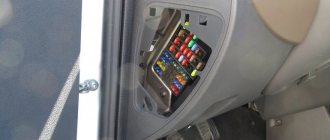
The fuse box is located in the car interior, on the driver's side under the panel.
Recommendation: It is strongly recommended to protect the unit from mechanical damage. Fuses should always be covered with a cover to avoid shorting the electrical circuit.
How to save 20% fuel?
Which gearbox is better for the classic VAZ 2107 2105 2106 2103 2101
This thing really saves 10-30% on gasoline. You simply install this device on the fuel supply hose and...
It is also worth paying attention to one of the design features of the car: all lighting is divided into two halves (left and right). There is a 50/50 chance that both fuses will blow at once, so in most cases your car will have lighting on at least one side
To repair, simply open the cover of the device and, using the table above, find the required element and replace it with a similar one. Please note that it is impossible to install fuses of a higher or lower value, since in the first case the wiring of the VAZ 2101 will suffer (the insulation is designed for lower currents), and in the second the fuse element will burn at the slightest load.
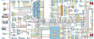
Features of the VAZ-2101 electrical circuit
For the VAZ-2101 there is also a standard electrical diagram compiled by specialists from the manufacturer of this car. Its main features are as follows:
- The DC electrical circuit is single-wire.
- The direct current connection is carried out from the “ground” to the “minus” terminal of the current source (on the VAZ-2101 such a conductive line “ground - minus” is the entire body, that is, all devices that consume electricity are connected by one wire to the “ground”-body) .
- The DC source is a battery with the following characteristics:
- brand – 6-ST-55 EM;
- voltage – 12 V.
- Alternator with the following characteristics:
- brand – G221;
- power – 500 W;
- the presence of selenium rectifiers (they are built into the back cover of this device);
- rated current – 42 A;
- maximum current at permissible load – 53 A (at 5,000 rpm);
- voltage – 14.5 V.
- Voltage regulator with the following characteristics:
- brand PP380;
- automatic adjustment (two-stage type).
- Battery with the following characteristics:
- capacity – 55 Ah;
- discharge mode – 20 hours.
All of the listed elements are connected to the VAZ-2101 using a parallel type.
For the VAZ-2101, a circuit of fuses has also been developed, which are needed to prevent a short circuit in the electrical circuit in a certain closed section (it is this that is sketched on the electrical circuit). For convenience and quick search for a failed fuse, the entire graphic diagram is divided into ten parts. This is exactly the number of fuses used on the VAZ-2101. They are also marked in different colors and numbered according to the actual data.
If one of the elements of the vehicle's electrical wiring is in poor condition, it will require immediate replacement. In this case, you cannot do without knowledge of the electrical circuit.
https://youtube.com/watch?v=CykyUv0BPY0
Cause of blown fuses
If a short circuit occurs, the current increases and a fire or failure of all electrical equipment may occur. This is protected by a fuse whose current designation is less than that of the device itself or the wires - so the fuse can melt.
The way each fuse works is that if there is a problem in the circuit, it will blow.
The main causes of burnout are:
- short circuit;
- a sharp increase in current in the circuit;
- failure of any electrical appliance;
- block wear or defects when replacing devices;
- poor quality equipment repairs;
Fuse box VAZ 2104 2105
Where is the VAZ fuse mounting block located: 2104, 2105 (carburetor, injector)
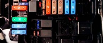
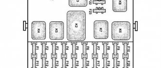
The mounting block is located in the engine compartment on the right side and is attached to the front panel. The mounting block is closed on top with a lid on which symbols for the purpose of the relay, fuse numbers and the circuits they protect are printed. Most of the vehicle's electrical circuits are protected by fuses installed in the mounting block.
| F1 | 10 | Tail lights (reversing lights). Heater motor Warning lamp and rear window heating relay (winding) |
| F2 | 10 | Electric motors for the windshield wiper and washer pump. Windshield wiper relay |
| F3 | 10 | Spare |
| F4 | 10 | Spare |
| F5 | 20 | Rear window heating element and heating relay (contacts) |
| F6 | 10 | Cigarette lighter. Portable lamp socket |
| F7 | 20 | Sound signals and relay for turning on sound signals. Engine cooling fan motor and motor switch relay (contacts) |
| F8 | 10 | Direction indicators in hazard warning mode. Switch and relay-interrupter for direction indicators and hazard warning lights in emergency mode |
| F9 | 7.5 | Generator voltage regulator (on vehicles with G-222 generator) |
| F10 | 10 | Turn indicators in turn signal mode and corresponding indicator lamp. Turn signal interrupter relay. Turn signal indicator Tachometer Fuel level indicator. Coolant temperature gauge. Voltmeter. Fan motor activation relay (winding). Battery charge indicator lamp. Indicator lamps for fuel reserve and parking brake activation. Warning lamps for emergency drop in oil pressure and insufficient brake fluid level. Indicator lamp for turning on the parking brake. Indicator lamp for covering the carburetor air damper (for a carburetor engine). Electric fan thermal switch. Carburetor pneumatic valve control system Generator excitation winding (generator 37.3701) |
| F11 | 10 | Rear lights (brake lamps). Body interior light |
| F12 | 10 | Right headlight (high beam). Winding of the relay for turning on the headlight cleaners (with the high beams on) |
| F13 | 10 | Left headlight (high beam). Indicator lamp for high beam headlights |
| F14 | 10 | Left headlight (side light). Right rear light (side light). License plate lights. Engine compartment lamp Indicator lamp for turning on side lights |
| F15 | 10 | Right headlight (side light). Left rear light (side light). Cigarette lighter lamp. Instrument lighting lamp. Glove compartment lamp |
| F16 | 10 | Right headlight (low beam). Winding of the relay for turning on the headlight cleaners (with the low beam on) |
| F17 | 10 | Left headlight (low beam) |
Connection diagram of the mounting block:
P1 — relay for turning on the heated rear window; P2 - relay for turning on headlight cleaners and washers; PЗ - relay for turning on sound signals; P4 - relay for switching on the electric motor of the engine cooling system fan; P5 - headlight high beam relay; P6 — headlight low beam relay; A - the order of conditional numbering of plugs in the mounting block blocks. The outer number with the letter “Ш” in the plug designation is the block number, and the inner number is the conventional number of the plug. The plugs of the blocks without color marking are conventionally shown in brown
Location of relays and fuses in the mounting block: 1 - relay for turning on the heated rear window; 2 — place for installing a relay for turning on headlight cleaners and washers (the relay is installed on some manufactured cars); 3 — mounting jumper in place of the relay for turning on sound signals (in a variant, a relay is installed); 4 — mounting jumper in place of the relay for turning on the electric motor of the cooling system fan (in a variant version, a relay is installed); 5 — relay for turning on the high beam headlights; 6 — relay for turning on low beam headlights;
F1-F17 - fuses (circuits protected by pin-type fuses are indicated in the table above).
Electrical equipment that consumes high current during operation is connected through relays that protect switch contacts from overload. To replace pin fuses and relays, special plastic tweezers are provided in the mounting block.
Fuses of different ratings are painted in different colors; In addition, the fuse is marked with a numerical value of the current for which it is designed (rated value).
The color of the fuse body and its correspondence to the rating 20A - Yellow 15A - Blue 10A - Red
7.5A - Brown
VAZ-2101 fuse diagram
The fuse diagram for the VAZ 2101 is practically no different from any other classic model.
| Fuse no. | Protected Circuits |
| 1.(16A) | This fuse is responsible for the cigarette lighter, the circuit of interior lighting bulbs, and the carrying sockets. It also protects against burnout of the horn and brake lights. |
| 2.(8A) | Protects the electric motor of the wipers, fan, interior heating, and windshield washer motor. |
| 3. (8A) | Responsible for the high beam on the left side and the lamp on the dashboard, which signals when the high beam is turned on. |
| 4.(8A) | Protects the high beam on the right side. |
| 5.(8A) | Responsible for the low beam wiring circuit on the left side. |
| 6.(8A) | Responsible for the low beam wiring circuit on the right side. |
| 7.(8A) | Protects the instrument panel lighting, trunk lighting, and license plate lamps on the left side from short circuits. Dimensions of headlights or fog lamps on the left side, as well as a warning lamp for the dimensions of the rear right lamp. |
| 8. (8A) | Responsible for the dimensions of the headlights or fog lamps on the right side, the license plate lamps on the right side, the indicator lamp for the rear left lamp dimensions, the lighting under the hood and the cigarette lighter lamps. |
| 9. (8A) | Protects the oil pressure warning light, the engine cooling system warning light, and the fuel level warning light. A lamp that indicates the handbrake is on, the brake fluid level, and the battery is charging. Protects the reversing warning lamp, direction indicators and their warning lights in the glove compartment. |
| 10.(8A) | Protects the voltage regulator and generator excitation windings. |
| 11 – 16 | For additional electrical equipment. |
Wiring harness in the cabin
The front wiring harness, located in the engine compartment, is the main electrical system. The front beam enters the car interior through a technological hole with a seal under the instrument panel. The front end electrical system connects to the dash wires, fuse box, switches, and ignition. In this part of the cabin, the main electrical circuits are protected by fuses.
The fuse box is located to the left of the steering wheel. Auxiliary relays are attached to the bracket behind the block. The reliable operation of the VAZ 2101 depends on the proper functioning of electrical devices and relays. Fuses protect the electrical circuits of the VAZ 2101 from short circuits.
Simple fuses are a reliable safety element in the event of a short circuit
List of electrical components protected by fuses:
- Horn, brake lights, interior lamps, cigarette lighter, portable lamp socket (16 A).
- Heating motor, wiper relay, windshield washer motor (8 A).
- Main beam of the left headlight, high beam indicator lamp (8 A).
- High beam of the right headlight (8 A).
- Low beam left headlight (8 A).
- Low beam of the right headlight (8 A).
- Side light of the left sidelight, side light of the right rear light, size indicator lamp, instrument panel light, license plate light, trunk light (8 A).
- Side light of the right side light, side light of the left rear light, cigarette lighter lamp, engine compartment light (8 A).
- Coolant temperature sensor, fuel level sensor and reserve indicator lamp, oil pressure lamp, parking brake lamp and brake fluid level indicator, battery charge level lamp, direction indicators and their indicator lamp, reversing lamp, glove compartment lamp ) (8 A).
- Generator (excitation winding), voltage regulator (8 A).
Video: replacing an old VAZ 2101 fuse box with a modern analogue
Switching of instruments in the cabin is made with low-voltage wires with elastic oil- and gasoline-resistant insulation. To facilitate troubleshooting, the wire insulation is made in different colors. For greater distinction, spiral and longitudinal strips are applied to the insulation surface to eliminate the presence of two wires of the same color in the bundles.
On the steering column there are contacts for switches for the direction indicator, low and high beam, and sound signal. In the assembly shop, the contacts of these switches are lubricated with a special conductive grease, which must not be removed during repairs. Lubrication reduces friction and prevents oxidation of contacts and possible sparking.
If the order of connecting elements is violated, traffic participants may be misinformed
Position numbers of electrical circuit elements on the turn signal connection diagram:
- Sidelights.
- Side direction indicators.
- Battery.
- Generator.
- Egnition lock.
- Fuse box.
- Relay interrupter.
- Power indicator.
- Switch.
- Rear lights.
The intermittent signal of the turn signals is determined by the breaker relay. The ground connection is provided by black wires, the positive connection is provided by pink or orange wires. Inside the car, the wires are connected:
- instrument panel and indicator lights;
- headlight clusters;
- direction indicators;
- interior lighting;
- wiper;
- foot-operated windshield washer.
The rear wiring harness runs along the left side of the cabin under the floor mats. A thread runs from it to the light switch in the door pillar and the parking brake lamp switch. The branch to the right lamp runs behind the rear beam along the floor of the body, where the wires connecting the level indicator and fuel reserve sensor are located. The wires in the bundle are secured to the floor with adhesive tape.
Mounting block in the cabin
In the first VAZ 2105 models, the fuse box was located inside the car. Such a block can still be seen today in some “fives” under the instrument panel next to the left door. Each of the fuses on the block located in the passenger compartment is responsible for the same section of the electrical circuit as the corresponding fuse on the block located under the hood.
How to identify a blown fuse
If problems arise with any group of electrical equipment in the car, the likelihood that the problem is in the fuse is high, but not one hundred percent. To make sure that a fuse has failed, sometimes an external inspection is enough: if there are burnt marks on its body, most likely the fuse has burned out. This method of checking is quite primitive, and in this case it is better to use a multimeter, which allows you to diagnose the malfunction:
- by voltage;
- by resistance.
In the first case it is necessary:
- Set the multimeter to voltage measurement mode.
- Turn on the circuit being tested, such as lighting, stove, etc.
- Check the presence of voltage at the fuse terminals. If there is no voltage at one of the terminals, the fuse must be replaced.
In the second case, the multimeter is switched to resistance measurement mode, after which the tips of the device are connected to the removed fuse. If the resistance value is close to zero, the fuse requires replacement.
If the resistance value is close to zero, the fuse requires replacement
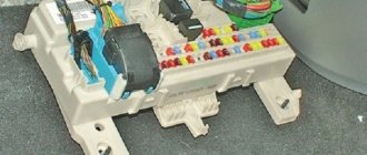
Unit dismantling and repair
The fuse box located in the passenger compartment is removed in the same sequence as that installed under the hood. It is necessary to unscrew the fasteners, remove the connectors and remove the unit. Just as in the case of the block located under the hood, repairing the mounting block installed in the cabin involves replacing fuses and restoring the tracks.
If the fuse blows on the road and you don’t have a spare at hand, you can replace it with a wire. But at the first opportunity, the wire must be removed and a rated fuse installed in its place. The fuse location diagram is usually shown on the inside of the mounting block cover.
It should be remembered that there are several types of mounting blocks that do not differ from each other in appearance. The differences lie in the wiring of the tracks. When replacing a block, you need to make sure that the markings of the old and new blocks match. Otherwise, the electrical equipment will not work correctly.
Old style fuse box
Old style mounting blocks use cylindrical (finger) fuses, which are installed in special spring-loaded connectors. Such connectors are not reliable and durable, which is why they cause a lot of complaints from car enthusiasts.
The old-style VAZ 2105 mounting block uses cylindrical fuses
Each of the 17 fuses located on the old-style mounting block is responsible for the same groups of electricity consumers as the corresponding fuses on the new-style block (see table above). The only difference is the rated current for which the cylindrical fuses are designed. Each plug fuse (on a new type block) has a rated current:
- 10 A corresponds to a finger fuse with a rated current of 8 A on an old-style unit;
- 20 A - 16 A;
- 7.5 A - 8 A.
Maintenance and repair of the VAZ 2105 fuse box in most cases does not cause difficulties for car enthusiasts. To independently determine the malfunction of the mounting block and fix it, even a little driving experience is enough.
For reliable operation of electrical equipment, it is important to use fuses with the parameters specified in the technical documentation
Complete diagram and arrangement of light and sound signaling elements...
presented in the diagram. True, the equipment of the VAZ-2105 is shown here. It differs from the VAZ-2104 only in a different shape of the rear lights, but otherwise everything is identical.
Scheme of light and sound alarm system VAZ-2105:
I – headlight; II – side turn signal; III – rear block lights; IV – interior lamp; V – license plate lighting lamp; VI – engine compartment lighting lamp; VII – diagram for switching on the headlights.
| 1 | Diffuser | 27 | PTF lamp |
| 2 | Lamp | 28 | Side light bulb |
| 3 | Lamp screen | 29 | Pay |
| 4 | Side light bulb | 30 | Reflector |
| 5 | Spring | 31 | Brake light |
| 6 | Emphasis | 32 | Board holder |
| 7 | Turn signal lens | 33 | Key |
| 8 | Lamp | 34 | Holder |
| 9 | Connection socket for hydraulic light position corrector | 35 | Power supply plug |
| 10 | Vertical light beam adjustment screw | 36 | Contact washer |
| 11 | casing | 37 | Spring pin |
| 12 | Screw for horizontal light beam adjustment | 38 | Lamp |
| 13 | bracket | 39 | Screen |
| 14 | Frame | 40 | Lamp |
| 15 | Reflector | 41 | Guide key |
| 16 | Adhesive layer for fixing the reflector | 42 | Lamp mounting bracket |
| 17 | Lamp | 43 | Headlights |
| 18 | Holder | 44 | battery |
| 19 | Holder with chuck | 45 | Generator |
| 20 | Plug stand for power supply and lamp mounting | 46 | Mounting block |
| 21 | Lamp | 47 | High beam relay |
| 22 | Plug stand for power supply and lamp mounting | 48 | Low beam relay |
| 23 | Ground connection plug | 49 | High beam warning lamp on the dashboard |
| 24 | Switch | 50 | Exterior light switch |
| 25 | Door switch connection plug | 51 | Egnition lock |
| 26 | Bulb holders-plugs | 52 | Light switch. |
The auxiliary equipment provides information to the driver about key engine parameters and also improves visibility while driving in bad weather conditions.
Auxiliary equipment includes sensors for monitoring engine operation (pressure, temperature, etc.), a cooling system fan, a system for washing and cleaning car windows (wipers, washers, glass heaters).
General principles of operation of electrical equipment on vehicles of the VAZ-2110 family
Basic principles of electrical wiring on a VAZ 2110 with carburetor and injection engines:
- All electrical equipment and devices powered by voltage are based on a single-wire connection. When developing the on-board network diagram, VAZ concern specialists thought out that electrical circuits of a certain color would be responsible for specific options. Therefore, certain devices are connected through power lines of certain colors. Thanks to this, the owner of the car can figure out the electrical circuit himself, which will allow him to carry out repairs on his own.
- The negative contact of any electrical appliance on the VAZ 2110 is ground. It connects to the vehicle body.
- The positive contact from the battery on a VAZ is always red. Therefore, when performing repairs, it is not recommended to change the color of the electrical circuit.
- Each electrical system connected to the on-board network has a separate harness with electrical circuits.
- “Ten” is designed in such a way that when the battery is activated, voltage is supplied to all electrical appliances and equipment. Therefore, when performing electrical wiring repairs from the battery, it is necessary to disconnect the negative terminal.
- Some VAZ 2110 cars are equipped with. This type of system began to be used to provide a higher quality spark compared to the contact version. A good spark is needed to ensure efficient combustion of the combustible mixture. For high-quality operation of the contactless ignition system, it is required.
Relay under the hood
Several relay elements are located in the engine compartment.
The turn signal and hazard warning relay (RS-491) is located on the bulkhead under the instrument cluster.
Headlight and battery charge relay
Scheme
Purpose
- Battery charge indicator relay (PC-702)
- Headlight high beam relay (VAZ-21011 and BA3-21013)
- Relay for low beam headlights (VAZ-21011 and BA3-21013)
1) Relay RS-702 is used to turn on the warning lamp on the instrument panel when the generator voltage is insufficient to charge the battery. 2) Headlights. On cars 2101 and 2102, as well as on 21011 produced before 1980, the headlights are turned on by a switch located on the steering column when the exterior lighting switch is on. On cars 21011 produced since 1980 and on cars 21013, the headlights are turned on by the same switches, but through auxiliary relays.
Still have questions? Ask them in the comments.
Fuse box VAZ 2101
- Fuse box
- Alternator Alternator Belt Tension
- Checking the generator on the stand
- Disassembling the generator
- Removing the generator
- Checking the starter on the stand
- Egnition lock
Purpose of the turn relay
The Traffic Rules in force in Russia clearly state that when making maneuvers, it is necessary to turn on the direction indicators, and in their absence, indicate the direction of movement with your hand. However, now most cars and motorcycles are equipped with turn signals, so you rarely need to use your hands to indicate the direction of travel.
When turned on, the direction indicators flash, that is, they light up and go out at certain intervals, so they attract the attention of other road users, and it is quite difficult not to notice the turn signal being turned on. The blinking of direction indicators also plays another role - it does not allow drivers to confuse their activation with the activation of brake lights or the inclusion of side lights
Periodic turning on and off (that is, the same blinking) of the direction indicator lamps is realized using a simple device that is part of the vehicle's electrical system - a turn relay, which is often simply called a breaker or breaker relay.
The breaker relay included in the turn signal circuit performs three functions at once:
- Supplying electric current to the direction indicator lamps (that is, turning on the “turn signals”);
- Ensuring intermittent operation of the direction indicator lamps (their blinking);
- Creation of characteristic clicks, signaling to the driver of the car that the direction indicators are working.
In cars of the Volzhsky Automobile Plant of various generations and models, several types of turn relays are used, which have different operating principles and characteristics.
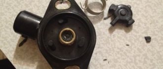
Removal and Replacement Guide
Before you begin replacing the safety devices located in the main unit, you must turn off the ignition and battery terminals under the hood.
The replacement procedure is carried out as follows:
- Find the installation location of the device. There are latches on the plastic cover of the block; press them. After removing the cover, you will be able to see a diagram printed on the reverse side, which indicates the location and purpose of all used elements.
- Then you need to identify which device has failed and needs to be replaced. Sometimes a breakdown can be determined visually - the component itself may be burnt out, sometimes a broken thread is clearly visible in it.
- Under the cover of the device you will see tweezers, which can be used to remove the device. If you don't have tweezers, you can use pliers.
- Remove the burnt out element and replace it with a new one, then replace the cover and connect the battery terminals (video filmed and published by the AVTOCLUB_22 channel).
To check and replace, follow these steps:
- First you will need a Phillips screwdriver, use it to remove the two switches located in the middle of the console, near the audio system.
- Using a screwdriver, you will need to press out two fasteners.
- Then remove the plastic insert.
- You can now remove the fuse housing. Remove the protective cover of the device and replace the part with a new one.
Removing and replacing the block with components is done as follows:
- First, open the engine compartment of your car and remove the air filter housing. Unscrew the nuts that secure the housing using a Phillips screwdriver.
- Then under the device you will be able to see a plug with cables connected to the device, you need to unplug it. The product body itself is marked in colors; it corresponds to the color of the connected connectors. By taking these plugs into account, the need to label cables can be avoided.
- After this, you should climb into the vehicle interior and remove the shelf, which is located under the control panel. After this, unscrew the bolts that hold the glove box housing.
- Next, disconnect the plug with cables connected to the connectors directly on the device. Once you do this, you will be able to see the color coding.
- Using a wrench, remove the bolts that secure the block itself. Please note that the outermost screw on the case is hidden, so you will not be able to see it immediately.
- At the end, remove the block with the devices, now the device can be replaced. Installation of a new device, as well as assembly of components, is carried out in the reverse order.
Fuse box VAZ-2105
The jumpers were made at home. Particles of molten metal freely penetrate into the environment, increasing the likelihood of fire in surrounding surfaces. F2, response current 8 A, allows you to protect the circuits of the windshield wiper and its relay, the electric washer motor and the heater.
This feature allows the existence of the following types of fuses, among which are popular: Open. Rear lights brake lamps.
First of all, you need to purchase LEDs, resistors, if it is difficult for you to calculate the value yourself, then you can ask the seller, heat shrink. The rest was all there: Time to create 2 days and then during the working day, without rushing: In the evening I will install it in the car!
Still, we couldn’t do without a pair of “spacer” nuts: - : 8. Relay for switching on headlight cleaners and washers K3.
Replacement is very easy and quick: Unscrew the nuts that secure the block and pull it out. More powerful fuses are usually installed under heating household appliances, washing machines, and refrigerators.
The breaker responsible for the operation of the direction indicators is located on the partition in the engine compartment opposite the dashboard. Most experts advise not to power a large number of different-sized electrical outlets, lamps, sockets, and household appliances using one fuse. LADA NIVA. Transition to a Euro fuse block.
Installing Euro fuses on a VAZ 2101
The price of a new VAZ 2101 fuse box will be about 400 rubles, which is not very expensive. Believe me, installing a new unit will solve a lot of problems associated with the electrical wiring of the penny. The procedure for replacing the old mounting block with a new one:
- Disconnect the battery.
- Make jumpers from female connectors, pieces of wire no more than 1.5 square meters. mm. and heat shrinkage.
- Install the prepared jumpers on the new mounting block. Connect the third and fourth, fifth and sixth, seventh and eighth, ninth and tenth.
- Unscrew both nuts that secure the block to the bracket.
- Without disconnecting the wires, remove the old unit.
- One at a time, connect the wires from the old to the new mounting block.
- After connecting all the wires, carry out a visual inspection and can be tested by applying power.
In order not to check the functionality of all the mechanisms that are included in the electrical circuit of the VAZ 2101, use a 12 V light bulb or a voltmeter.
Using one of these tools, check for voltage at the output of each fuse. After this, install the plastic housing and screw it to the bracket with nuts. Close the lid and enjoy using it. Believe me, now you will look there very rarely.
In this article you will learn how to replace a standard fuse block with a Euroblock. To begin work, disconnect the battery terminal. Next, take an 8 mm wrench and unscrew the old fuse box, without pulling out the wires. Then take a piece of paper and draw a 10x3 sign.
Why is all this needed? If you immediately pull the wires out of the fuse box, then I assure you that when you connect the wires to the new block, you will get confused and connect them incorrectly. Therefore, sketch out the connection diagram in a table on paper. Then take regular paper tape and tie the wires together. Let's look at the old fuse block, and we see that contacts 3-4, 5-6, 7-8, 9-10 are bridged, and their fuses are located at the bottom. Approximately the same picture will need to be recreated on a new block. In total we will need four jumpers. This is done very simply. Each jumper consists of a small segment of the “mother” type. This kind of work can be freely done with your own hands.
The next step is to carefully connect the required fuses with jumpers, while trying not to mix anything up. After this, you need to connect all the wires to each other. Start with the first fuse. Be sure to follow the sequence that is sketched on your paper. Keep in mind that on the old (standard) fuse box the top two wires are connected vertically, but on the new fuse box they will be connected horizontally
Note! Before connecting all the wires, it is worth sealing the female terminal of each wire, since they are too close to each other. The new fuse box may have a short circuit.
After you have completed all the work, turn on the ground and check all circuits for functionality.
In this article, clearly, using photos, materials are provided on how to correctly replace fuses on a VAZ 2101. In addition, the article details the design features of the mounting block of this car model and provides guidelines for servicing and replacing the fuse block. The Zhiguli car has long become a cult model of the domestic automobile industry. This legendary car once won the hearts of many car enthusiasts. And, what’s most interesting, many car owners, having purchased a fairly expensive modern car model today, continue to keep their favorite “penny” and carefully look after it. However, this car still serves faithfully for many motorists. And, despite their age, these cars look great and are in excellent condition. All this thanks to timely maintenance and high-quality repairs. But to a greater extent, in this case, the driver’s attitude towards his car plays a role. Next, it is proposed to consider the features of servicing a specific unit in this car, namely the fuse box.
Replacing the old unit with Euro fuses VAZ 2101
It would be more advisable to install a new type of fuse block. Its price is reasonable - about 400 rubles. For this small cost, you can improve the wiring throughout your entire vehicle.
Work that needs to be done to replace the mounting block:
- The terminals from the battery should be disconnected.
- Make jumpers from pieces of wire 1.5 sq. mm on both sides of the female connector.
- These jumpers must be installed on the new block, connecting the connectors: third to fourth, fifth to sixth, seventh to eighth and ninth to tenth.
- Then you need to unscrew the two nuts that secure the mounting block and remove it without disconnecting the wires.
- After this, you need to remove the wires one at a time so as not to mix them up and put them on the new unit.
- After the wires are connected, you should carefully inspect them so that they do not touch each other anywhere, and only then connect the power.
In the end, it should be said that in order to check the operation of the mechanisms included in the VAZ-2101 circuit, you can use a voltmeter or a simple 12-volt light bulb. It is necessary to check the voltage at the output of each fuse. Then tighten the two nuts and secure the plastic shield.
Main difficulties of repair
The biggest difficulty, especially for novice car enthusiasts, is the fact that the wires in the electrical circuit and in reality can be marked with different colors. This problem is very relevant for “old” cars that have been repeatedly repaired. Previous owners are rarely puzzled by the problem of maintaining the correct color of the cables, installing the first ones that come to hand. In this case, the new owner will have to spend time finding out what the former owner has changed.
Even more difficult are situations when a wiring change has been started but not completed. In this case, it will be even more difficult to navigate. Trying to figure out where a particular guide leads can take days, and sometimes weeks. Therefore, if you purchased a car with unfinished electrics, it is better to purchase a kit and make the connection according to the specified diagram.
This solution has immediate double benefits. Firstly, you will be able to understand which cable leads to which consumers, and secondly, old electrical wiring, which may not be working, will be eliminated. New wires will serve you reliably for a certain period of time, which means you won’t have to worry about ringing the circuit a month after purchasing the car.