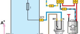
Scheme for connecting the alarm system to the Central Lock on a Priora
This diagram is the simplest diagram for connecting an alarm system to a standard Priora Central Lock.
To implement this scheme, we lay two wires in the driver's door and connect them to the gap in the brown wire between the electric drive and the driver's door module.
When connecting the central locking according to this scheme, all doors will close, and only the driver’s door will open, the rest are opened by a button in the driver’s door.
If the standard alarm is activated, you can reprogram it so that all doors are opened simultaneously using the alarm key fob. To do this, with the ignition on, press both buttons on the key simultaneously until the signal sounds. One signal enables this function, two signals disable it.
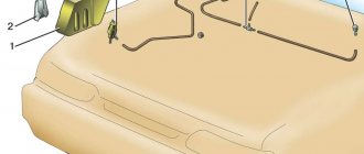
The alarm connection points for Priora are located here.
Many car owners prefer to install security equipment on their own. For self-installation, you need to determine the alarm connection points on the Priora, and then connect the cables with subsequent insulation of the joints.
Let's start with the driver
In Kalina, Priora and Grant the fastening scheme is identical. To remove the driver's door trim, since it is held in place not only by screws, one Phillips screwdriver is not enough. You will need something else sharp and flat. So, first, let's deal with the obvious hardware. The first is at the bottom of the door. There on all these models there is a plastic pocket, at the bottom of which there are two recessed holes. It is in them that the screw heads are visible. It’s not very convenient to get into it with a screwdriver with a long blade, so if possible, take a short one. Then locate the plastic plug near the door handle. Pry it with the same sharp object that we mentioned above, and you will find a screw there. Another one is hidden at the base of the opening handle. Bend it to its extreme position and unscrew it. Well, there is another one in the recess on the body. We think it would be unnecessary to mention that you should put all these screws separately so that you don’t frantically search for them and lose them later. Finally, unscrew the door lock cap.
Before you begin removing the driver's door trim, check that you have the clips. If you couldn’t find them, be very careful, because it’s on them that, in fact, everything rests. Using a knife or flat screwdriver, pry the panel off and snap it away from the door body. Remember that the clamps are very fragile and break under the slightest load. Then disconnect the speaker chip and move the rod to the side, if it is attached. That's all, now you have a bare door and you can do what it all started for. By the way, we recommend removing debris and moisture from the door, if possible, and cleaning the drain holes, even if you did not dismantle the door for this purpose.
Two schemes (simple and complex)
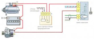
First of all, before connecting the alarm, you need to study the instructions included with it. The main unit always has relays installed: one of them closes when the locks are locked, the second acts on opening. The connector to which the relay contacts are connected usually has 6 pins. There is nothing complicated here.
In the first case, we will use only this connector. The second circuit uses another contact, called “signal output for 2-step lock opening”. Find it on the main unit.
We connect the alarm in a simple way
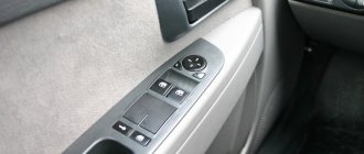
A push-button module is installed in the driver's door of the Lada Priora. The door trim must be removed and the connector for this module must be found:
We will need a brown cord from the connector. It is a signal, and the alarm relay is connected to its break:
Device
The weakest point of the Priora locking system is the microswitch. The electrical package itself, used on the model in question, is a rather complex device. It is his responsibility to receive the owner’s command to unlock or lock the door. Having received a certain signal, it activates certain electrical networks that supply the drive. In this case, the electrical package can perceive orders in two ways at once:
In the first case, having sensed the order to close, the immobilizer turns off the alarm and energizes the electric drive of the lock, closing or, conversely, opening the contact groups of the microswitch.
Then the latter, all the time the lock is locked, monitors whether an order has been received to open the doors.
Why is everything arranged this way? Everything is simple, because the command in this situation can be received not only from the key fob, but also from the switch if the car owner used the key. This allows the immobilizer, when the security alarm is activated, after detecting a raised blocker, to immediately begin to act according to the alarm protocol.
Connection points
Power is supplied to the security system from the ignition switch; the negative terminal is attached to a metal element connected to the car body. To operate the remote engine start unit, you need to use the cable coming from the limit switch under the parking brake lever. Information about the operation of the motor is transmitted to the head unit via a separate cord connected to the speed sensor.
Lada Priora alarm connection points include cables going to switches mounted in the doors, under the lids of the luggage compartment and the power unit compartment. Additionally, the wires of the original siren (or an alternative unit) are connected. If the alarm system supports switching of the CAN-LIN digital bus, then it is also necessary to connect the points (in accordance with the factory documentation).
- Repair of door locks for VAZ 2108, VAZ 2109, VAZ 21099 cars
Connecting the central lock
To connect the alarm system to the Priora central locking system, a cord is used that goes to the control controller. The cable is covered with brown insulation. With a direct switching scheme, all door locks are locked simultaneously, but when the security is disarmed, only the driver's door will open. If the car owner wants to open other doors based on a signal from the remote control, then a 2-stage shutdown scheme is implemented.
The car owner connects an additional relay to the circuit, which operates in parallel with the contact units for blocking the power windows of the doors. If you do not install a window drive relay, then when a signal is sent to the central locking system, the motors will briefly operate (to lower or raise the windows). This occurs due to the design features of the electrical wiring harnesses and electrical components installed in the doors of Priora vehicles. Some cars use 1 relay (in the absence of rear electrical mechanisms).
Circuit breakers
If the lock stops working, you need to check if there is power in the circuit. Most often the fuses blow. They can fail not only due to a short circuit, but also due to overload. The latter often occurs if the rods do not work properly (for example, they have not been lubricated for a long time or have frozen if the breakdown occurred in the cold season).
Meanwhile, if burnout occurs regularly, then you need to find out what exactly provokes this breakdown. Often it is the activator that causes frequent short circuits.
Notes on implementation of schemes
Let us immediately note: if there are no window lifters, the second diagram will not contain parts K2/K3. Then you only need to cut one wire. Sometimes only the rear windows are missing. This means that relay K3 is excluded. And the diodes connected in parallel with the winding can be absolutely anything.
Now we list the requirements for an element called “relay”:
- Operation voltage - 12 Volts;
- Switching current - 10 A or higher;
- The current consumed by all relay windings should not exceed the value specified in the instructions for the signaling. Usually it is 200-300 mA.
It is the last requirement that is often violated.
In order for “scheme 2” to work, it is necessary not only to assemble it, but also to program the main unit: you need to enable the “2-step unlocking” option. And be that as it may, control impulses cannot be made too long. Use values of 0.7-1.1 seconds.
Connecting limit switches
The signal cables from the limit switches are connected to the electrical control unit, which is located inside the car. From the front doors there are cables with blue-black and brown insulation; wires with gray-red protection are laid to the rear elements. An additional yellow-red cord is routed to the luggage compartment lid lock. The engine compartment hood switch is covered with white and black insulator. Before starting the connection, it is recommended to check the purpose of the cables according to the electrical diagram of the machine.
Features of electrical equipment
The electrical circuit of a Lada Priora car includes several main elements - front and rear blocks, control panel blocks, as well as engine control systems. All these elements are connected to each other by special plugs located on the left under the center console, as well as above the mounting block. Only the control panel and engine control system harness is located in the heating system shaft, on the driver’s side. It should also be noted that the rear block and the device are connected to the control device via an electrical package, which is located inside the car.
The main systems that the electrical circuit includes:
- heating unit, stove;
- optics, including main headlights, dimensions, fog lights, turn signals;
- windshield and rear window cleaning system, if provided for by the vehicle design;
- car central locking;
- electric windows.
Diagnostic tester with test lamp for checking electrical circuits
Installation and connection instructions
Installing an alarm system on a Priora begins with determining the locations of the security complex blocks. During installation, it is necessary to ensure a minimum length of connecting cables; it is prohibited to place modules on standard electrical appliances. Some Lada 2 Priora cars use a factory security system with a control panel located on the head of the key. The standard alarm unit on the Priora is located in the car's interior under the lining of the floor tunnel. When installing additional protective equipment, the standard device is disabled.
Do-it-yourself alarm installation begins with the installation of the head unit, which is located inside the instrument panel. The unit is located at a distance from the cabin heater; it is recommended to tilt the module with the plug down to drain the condensate. The positive power pulse comes from the ignition switch; a fuse is provided in the circuit (the rating is indicated in the documentation included with the car alarm).
The antenna unit is placed on the windshield; some alarm systems allow for discreet placement of the unit (with a reduction in the range of the remote control).
To improve the quality of the communication channel, it is recommended to lay the connecting cable at a distance from the factory electrical wiring.
When using equipment with autostart, it is necessary to install a temperature sensor in the engine compartment; On some alarm models, a separate relay block is used, which ensures starting the motor from a distance.
The shock sensor is located inside the car (piezoelectric microphone) or inside the head unit (3-axis acceleration sensor). When installing equipment, it is necessary to display a control LED on the rack casing, as well as a programming switch. The head wiring harness is connected to the central locking unit and siren located in the engine compartment. An additional alarm channel is used to control the trunk lid lock. Connections are made in accordance with the factory instructions.
- Why the central locking on the VAZ-2112 does not work: the main reasons
Video “Do-it-yourself restoration of electrical wiring in Priora”
Visual instructions for independently restoring the functionality of the wiring in a Lada Priora car are shown in the video below (the author of the video is alecsey avtolekar).
The Priora central lock does not have a separate block like on other VAZs. The role of the Priora central locking unit is played by the electrical package controller. In addition, the central locking is included in the standard security system installed by the factory, the APS-6 immobilizer. This system allows you to avoid installing an additional security alarm. The car comes with three keys: a main key, a spare key and a training key with a reddish insert, in which chips are installed to identify the keys by the security system.
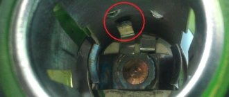
Characteristics and principle of operation of the blocker on Priora
Priors can use two types of immo - APS-4 and APS-6. The first ones began to be installed on VAZs back in the early 00s and are considered less reliable.
In the blocking device on Priora, the main role is played by the PIC16С65В controller and the K-Line bus. And the main element of the microprocessor module for working with the blocker is the physical section EPROOM. The latter records a special file with the same name, contained in the memory of the ECU (electronic control unit). It stores immobilizer learning combinations and it is this element that is responsible for the safety of the vehicle. If the file is activated and the blocker does not send a signal, the microprocessor module opens the ignition circuit and turns off the fuel supply system.
In more detail it looks like this:
- The driver, approaching the car, presses a button on the remote control.
- The doors open and the key is inserted into the ignition.
- A signal comes from the chip and is fed to the antenna adapter.
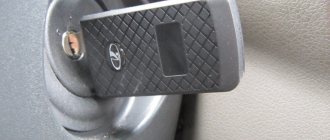
- The ring-type antenna begins to read the pulse from the chip. This element is made of a large number of turns of copper wire. The antenna adapter itself is located around the ignition switch cylinder.
- The pulse, after reading, is transmitted to the microprocessor module. The control unit begins diagnosing the signal and compares it with the normalized one. As a result, it gives a command to allow or prohibit the start of the power unit.
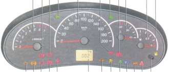
- If the key is not recognized and the device begins to block the main components, then an indicator is displayed on the control panel indicating a faulty immobilizer.
Auto electrician Sergei Zaitsev spoke about the principle of operation of the standard anti-theft system.
Where is the immobilizer located?
In the first models of vehicles with security devices, the immobilizer unit was located separately. But in Priors it is installed in the electrical package. The device is mounted in the car radio compartment, slightly below the central part of the console in the cabin. The microprocessor module is also located here.
Lada Priora alarm connection points.
| Chain | Wire color | Polarity | Location |
| Weight | M6 nut near the mounting block | — | |
| Food +12 | Brown | + | Ignition switch |
| Ignition | Blue with black | + | |
| Starter | Red | + | |
| Nutrition +12 (second option) | Red | + | BUS, connector X1 |
| Turns | Blue | + | |
| Turns | Blue with black stripe | + | |
| Ignition (second option) | Orange | + | BUS, connector X2 |
| Hood switch | White with black stripe | — | |
| Driver's door - limit switch | Blue with black stripe | — | BUS, connector X3 |
| Passenger door - limit switch | Brown | — | |
| Rear door - limit switch | Gray with orange stripe | — | |
| All doors (with interior lighting delay) | White with black stripe | — | |
| Trunk - trailer | Yellow with red stripe | — | |
| Opening the trunk | Blue with red stripe | — | |
| Ts.Z. (open) | According to the diagram below | ||
| Ts.Z. (close) | |||
| Handbrake (via diode) | Brown with blue stripe | — | Dashboard |
| Generator | Brown with white stripe | + | |
| Tachometer | Brown with red stripe | + | |
| Can tire High (since 2013) | Yellow-red | Diagnostic connector | |
| Can tire low (since 2013) | Grey | ||
| LIN bus (since 2013) | Blue-white | Driver's door harness |
Priora controller connector: how to properly connect the alarm system
Installation of the security system is quite simple and the primary connection points for the Priora alarm system are located on the controller connectors. First of all, connection is made to X1: 12V power supply to the red wire (numbers 2,3), turn signals are connected to the blue and blue with a black stripe wire (pins 14 and 15).
This connection stage is responsible for the normal functioning of the turn signals during alarm installation. And in addition, they will guarantee the correct operation of this part of the car’s electronics.
Next, work is done with connector X2, to which the wires from the ignition and hood will be supplied and connected. To connect the ignition, you will need to connect the orange wire (numbered 9) to the connector. A white wire with a black stripe (pin 17) is connected from the hood. This work is carried out for the following cases:
1. Preventing an attacker from trying to open the hood.
2. Prevent attempts to damage or remove the battery.
3. Normalization of autorun operation.
4. Correct functioning of the protection system.
The next step will be for Priora to connect the connection points on the last X3 connector. The work is quite simple and consists of connecting the wires leading to the limit switches. For the front doors, you will need to connect the brown wire (pin 7) for the passenger door and the blue/black wire (pin 6) for the driver's door to the connector.
Next, connect the yellow wire with a red stripe (pin
from the trunk and a gray wire with a red stripe (pin 1) for the rear doors.
LADA 2170
Instrument panel diagram
Communities Lada Priora Lada Priora Club Blog what affects the clutch release limit switch
1, 2, 3, – instrument panel harness connectors to the front harness 4 – instrument panel harness connector to the rear harness 5 – contacts of the mounting block connector 6 – brake light switch 7 – instrument cluster 8 – lighting control module 9 – driver airbag module 10 – sound signal switch 11 – diagnostic block 12 – on-board computer mode switch 13 – ignition switch 14, 15 – blocks to the electric amplifier control unit 16 – electrical package controller 17 – light alarm switch 18 – windshield wiper switch 19 – air flow distribution gearmotor 20 – block heater control 21 – heater electric motor switch 22 – rear window heating switch 23 – clock 24, 25 – instrument panel harness connectors to the radio 26 – hazard warning switch 27 – glove compartment lighting switch 28 – glove compartment lighting switch 29 – instrument panel harness connector to ignition system harness 30 – airbag system control unit
Front Wire Harness Connection Diagram
1 – starter 2 – battery 3 – generator 4 – battery harness and starter and front harness connectors 5 – 7 – front instrument panel harness connector 8 – engine compartment lamp switch 9 – left headlight 10 – right headlight 11 – brake fluid level sensor 12 – sensor air temperature 13 – washer motor 14 – reverse light switch 15 – engine electric fan 16 – heater damper gear motor 17 – additional resistor 18 – windshield wiper motor 19 – main fuse block 20 – heater motor 21, 22 – sound signal
Ignition system diagram
1 – controller 2 – ignition system harness connector to the instrument panel harness 3 – main fuse box 4 – speed sensor 5 – rough road sensor 6 – oil pressure warning lamp sensor 7 – throttle position sensor 8 – coolant temperature sensor 9 – pointer sensor coolant temperature 10 – mass air flow sensor 11 – idle speed control 12 – fuel pump relay 13 – fuel pump power supply circuit fuse (15 A) 14 – ignition relay 15 – ignition relay fuse (15 A) 16 – controller power circuit fuse (7, 5 A) 17 – crankshaft position sensor 18 – oxygen sensor 19 – phase sensor 20 – knock sensor 21 – canister purge solenoid valve 22 – diagnostic oxygen sensor 23 – ignition coil 24 – spark plugs 25 – injectors 26 – ignition coil wiring harness block to the ignition system harness 27 – ignition system harness block to the ignition coil wiring harness 28 – ignition system harness block to the injector harness 29 – injector harness block to the ignition system harness
And here are the electrical diagrams of the Lada Priora Lux.
CAR ELECTRONICS REPAIR BATTERY CHARGERS
Preparing for self-installation of central locking
The complexity of installation directly depends on the brand of car. But, in fact, cases when something needs to be filed and drilled out for a long time are rare. These mainly include long-lived cars, which are at least thirty years old. In most options, the car is already prepared for installation of the central locking system. All that remains is to put the kit in place. Well, the second side of the issue is the set itself. If you don’t want to dig around for a long time, buy universal locks. Installation is simple and you will find plenty of information on them.
What's in the basic kit?
We take the simplest universal kit. Control, in our case, will be carried out from a special key fob. Usually there are two. There is an option when the system will be activated by turning the key in the driver's door lock. You can also display a special button in the car interior. This additional option is very nice if you need to lock the doors while driving. It is not always convenient to use the control panel.
So, we purchase a universal lock kit, which in most cases includes:
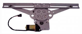
- Four motors. They will be attached to the door. One of them with four wires is on the driver's door;
- Control block. We will subsequently connect all the wires to it;
- A set of wires of the required length. If you feel that there are not enough of them, buy additional ones immediately;
- Key rings, strips, screws, etc.
central locking
Necessary tools for work
Now we are assembling a tool that will be useful to us in our work. If there are no holes for mounting motors in the doors, then prepare a drill with a drill bit. Also needed: screwdrivers, a screwdriver, a knife, corrugated tubes (wires are laid through them to avoid chafing and the influence of external factors on the wiring) and electrical tape. We will rewind all exposed sections of wires with tape in order to avoid their contact with metal parts of the body.
The last thing to do before proceeding with installation is to remove the trim and dust curtains from all doors. Determine the location where you will mount the mechanism so that it does not interfere with the operation of the window regulators. If necessary, you will have to make an additional bracket.
Installation of central locking
All necessary preparations have been made, and you can begin to work. We attach the motors to the doors, remembering that we place the motor with four wires on the driver's door. We also install the control unit there.
Connection diagram
After installation, we check the correct interaction with the lock rod, which is responsible for opening and closing the door, and the smooth operation of the lock itself.
Let's move on to the wires. We pull them from each motor to the control unit. Think in advance about how to pull the wire from the rear right door. You can use the space under the seats. We connect them according to the circuit and perform the test. To do this, return the battery to its previous state. If you find any faults, first check that the connections are correct. The plus and minus outputs may be confused. When checking, it is better to be inside the car or not to close the doors. Once you restore battery function, the locks should work automatically.
Installed and connected motor
If you still want to make a lock control button, prepare the missing parts in advance. Additional wire and button. It can be embedded into the dashboard. Buy any button, for example, for a window regulator.
Installation of the central locking control button
We look for the black, brown and white wires under the side panel and connect to them. Alternatively, you can stretch the wires and connect to the electrical bundle from the central locking of the driver's door. And we carry out the rest of the connection according to the diagram.
Connection diagram for the central locking control button
Connection diagram for the central locking control button
It is absolutely not necessary to make this button on the panel. Again, it all depends on convenience. You can place it in the space between the front seats if the necessary electrics are there. Alternatively, the button can be embedded in the armrests on the doors.
The trunk can also be connected to the central locking. Which, by the way, will also significantly save your time and nerves. If you have a wiper on the rear window, then the necessary electrical wiring is already installed, and connecting will not be difficult. The main thing is not to forget that central locking still cannot secure your car one hundred percent. Such options must be used comprehensively and, of course, an alarm system must be installed.
Kia Rio G4FA or still G4FC?
Hello everyone, my dear readers, there are more than 1500 of you, I am very pleased that I bring some benefit *probably*. So today we will talk about a non-standard, but quite interesting situation with a Kia Rio car with a 1.6 engine. An acquaintance of an acquaintance bought a car for restoration, as indicated above, a 2013 Kia Rio with a seized engine. Well, it seems like an everyday matter, well, I caught the wedge, we’ll fix it. We disassembled the engine, checked the condition of the crankshaft, connecting rods, pistons, block, and so on, the condition, as they say, is not standing. The diagnosis needs to be changed. He went to a good office, they twisted his knee and said the patient was more likely dead than alive. Well, what problem do you have with the crankshaft, he asked, of course there is, the master answered, and he asked the client from my car, of course from yours, I’m not a fool, the master answered. This is how this interesting story began. We ordered using the VIN number of the connecting rods and piston. And we started assembling the motor. The car was ready and running quietly and amazingly, but there was just one problem. Power. The car did not drive either from the bottom or from the top. These are the situations, of course, but then they started replacing a bunch of sensors, removing catalysts and similar actions that did not lead to any result. This Epic lasted for a year. A friend calls and says: There is an interesting case. I always like interesting cases and he tells me everything that was described above, I’m a little in a stupor, but I really want to make such a car. Upon arrival at the car, as always, I turn on the diagnostics and quickly examine the errors and parameters in real time:
Revolutions - 750 revolutions;
Short-term balancing - 1%;
Long-term balancing - 0%
Pulse to injectors - 2.3 m.s.
MAP (intake pressure sensor) - 60 Kpa
Lambda. What. I don’t understand 60Kpa. Once again I run 60Kpa again. There is a clue as to where this pressure in the intake comes from. I turn on the ignition 99Kpa, theoretically the sensor is working, and it’s already new here. I take about 3 devices and they all show the same thing. I think, well, how to measure compression, the car works smoothly. Let's go climb with the magnificent Postalovsky, I bow my head to its developers and creators. First I take an oscillogram of the crankshaft and camshaft, everything is fine.
I tighten the pressure sensor and do a sprint RX. And I start to think, why the hell is the compression ratio so low?
Okay, I’ll look at it on a working car since I save all the tests for myself. And everything is fine there. Here are two tests: on the right is a working motor, on the left is mine.
Features of connecting the alarm to the lock on the driver's door
Installing a central lock on the driver's door allows the owner to avoid the main reason for car theft: opening one of the passenger doors. That is why you should carefully study the car alarm connection points on the Priora in order to ensure maximum protection and ease of use of the vehicle.
For the central locking to function, you will need to connect two wires to the driver's door. They should be triggered by a break in the brown wire when the lock is closed and, accordingly, the locking buttons are activated.
For the modern Lada Priora, the alarm connection points responsible for the normal operation of the autostart are also very important. You will need to connect a brown wire with a red streak to the dashboard connector. And the brown/white wire is connected to the generator. All this allows you to control the autostart procedure. The last connection point will be the brown/blue wire from the handbrake.
Upon completion of the full procedure for searching for points and connecting the corresponding wires to them, you need to visually evaluate the connections and check the operation of the alarm in action. Until the moment of complete reliability in the correct functioning, the Lada Priora alarm connection points must remain open.
This will allow you to immediately begin correcting them if any problems are detected. Once the goal is achieved, the plastic of the front panel and tunnels can be replaced.
Adjustment on Kalina
Typically, it is necessary to adjust the operation of the lock on this model if there is excessive noise that occurs when closing the doors. It rarely gets to the point where the locking device works poorly. To work, you need a Phillips screwdriver, a wrench and a screwdriver with an asterisk. The work is carried out in the following order:
- Using a screwdriver, loosen the screws securing the clamp. It is secured with two Phillips screws and one sprocket;
- We make adjustments. The shift here is made up or down;
- Tighten the screws in the selected position.
To reduce noise, you can put a silicone cap on the clamp. If this procedure does not help, then it makes sense to tighten the screws securing the door hinges.
Why is everything so difficult?
It would seem that we only need to manage the locks. Why then connect to the window lift motors?
All relays operate simultaneously
The opening of the passenger doors is carried out by the second impulse (relay K1 is activated). And elements K2 and K3 at this moment block the power windows. If they are not blocked, the windows in the doors will lower during the entire control pulse. And even in 0.8 seconds they will open noticeably.
Of course, connecting the signaling system in a Priora is more difficult than in many domestic cars. At the same time, the “Grant” in the “Norma” configuration uses a similar scheme. Be that as it may, the Lada Priora is the flagship of VAZ. And probably, difficulties with the electrical part should not confuse a competent car owner. It is also known that the standard control unit can be reprogrammed, and then unlocking occurs in one step. In this case, the connection is made according to “Scheme 1”.
Wiring
In general, the wires remain a weak point in Priora, and so far the manufacturer has been unable to do anything. For this reason, it is extremely important to regularly check their integrity. This is a labor-intensive task, but very necessary.
They start testing them from the doors - it is at the points of their entry that the insulating layer is most often damaged, which, in turn, provokes a short circuit. The procedure looks like this:
- the wires are disconnected from the activator;
- use a key fob to close the lock;
- the power wire must be live;
- If you open the door, the electricity will flow through another vein.