Auto manufacturers today use many technological solutions to ensure more comfortable driving. One of such devices is CBKE. What is the central unit of body electronics Kalina 2 needed for, what functions does it perform and what malfunctions are typical for it - read in this article.
Description of CBKE
Unlike the first Kalin models, the second versions and Luxury equipment use an electrical package control unit instead of traditional relays to control the electronics. This device combines many functions, we suggest you familiarize yourself with them in more detail.
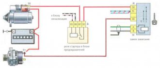
Connection diagram of elements and outputs of the CBEK
Functions
The electrical package control unit is designed to perform the following functions:
- Alarm. If the car's anti-theft system detects a break-in attempt, thanks to the CBKE, it will transmit information about this to the car owner's control panel.
- Windshield wiper system control. Moreover, we are talking about both manual and automatic control (if the car is equipped with an electrical package control unit marked 21900-3840080-20).
- The device performs the function of controlling the windshield and rear window heating systems. This unit also controls the heating elements of the side rear-view mirrors.
- The electrical control unit also monitors the performance of the optics, both in manual and automatic control modes. In particular, we are talking about low-beam headlamps, side lights, and DRLs.
- Separately, we should highlight the function of ensuring the functionality of the high-range lighting.
- Turning lights, as well as light signaling.
- Vehicle interior lighting.
- The device monitors the performance and energy saving of devices belonging to the category of internal lighting of the car.
- Monitoring the state of the central lock, as well as performing the functions of locking and unlocking the locks themselves from the key, from buttons installed in the car interior, as well as in the doors.
- Another option is to open the luggage compartment lid using a button installed in the cabin.
- An equally important function is the control of electric drives, in particular, we are talking about power windows, as well as side rear-view mirrors.
- Heating system for driver and passenger seats.
- Luggage compartment lighting unit (video author - Vladimir Kostyuchenkov).
Typical faults
If the electrical package control unit fails for some reason, this can lead to the following problems:
- Failure to operate power windows. Of course, before disassembling the control module, you should make sure that the window regulators do not work precisely because of it. It would be logical to first check the safety element, as well as the lift control unit, which is built into the driver's door. In practice, it often happens that the cause of power window failure is poor wiring contact on the unit itself.
- The optics stopped working - low beam, turn signals, etc. In this case, the safety elements, light sources and steering switch are first checked. There is a possibility that the reason lies in a broken contact directly on the switch; if this is the case, then they should be re-soldered. If the reason is that the unit is not working, it will need to be dismantled and disassembled in order to find the burnt-out element and re-solder it. If soldering does not help solve the problem, the device will have to be replaced.
- Some of the equipment has stopped working, while the devices, as at first glance may seem, are in no way connected with each other. The fact is that the module itself includes many elements and controllers, each of them is responsible for performing certain functions. If two or more controllers fail at once, it can cause serious damage. For example, the optics, heated rear and front windows, the trunk door and the window regulator will immediately refuse to work. It is necessary to locate the failed controller and replace it by re-soldering.
- A fairly common problem that can occur is a break in the wiring of the unit. It is installed in a virtually inaccessible place, but if electrical work is being done, for example, installing an anti-theft system, then most likely the car owner will encounter a TsBKE. And if the wiring is damaged during the work, of course, this will affect the functioning of the device and, accordingly, the performance of certain functions.
- Oxidation of contacts on module connectors. If you encounter such a problem, we recommend paying attention to the humidity in the cabin. Often, oxidation at the outlets occurs precisely as a result of high humidity. The contacts can be cleaned, this is not a problem, but the problem of humidity must be addressed, since otherwise it can lead to failure of the microcircuit as a whole.
- Board failure. The most terrible problem for the car owner, because because of this the device simply will not be able to work normally. Accordingly, it will need to be replaced, and this, in turn, costs a lot of money (author - Alexander Fisher).
Preparing databases before synchronization
Creating a Backup
Before setting up synchronization and performing the first synchronization, it is strongly recommended to create backup copies of the information databases of both 1C ZUP 3 and 1C Accounting 3.0. The easiest way is to create a backup copy directly from the program. To do this, use the backup service in the Administration – Maintenance – Backup and Restore section (link Create a backup copy). In the window that opens, you must specify the path to the directory in which the backup copy will be stored.
Here, if necessary, you can restore the database from a backup copy - link Restore from a backup copy.
All methods of creating backup copies using the example of 1C Accounting 3 are discussed in more detail in the article Backup 1C 8.3 Accounting 3.0. For ZUP 3 the same techniques are used.
Check the relevance of releases in 1C ZUP 3 and 1C Accounting 3.0. Update if necessary.
To perform synchronization correctly, it is very important that program releases are up to date. If, for example, the release of 1C ZUP 3 is current, and the release of 1C Accounting is two months old, then errors are possible when performing synchronization
Therefore, you should monitor the relevance of program releases.
You can read about how to properly update in the article 1C Update: how to update the configuration yourself.
Replacement features
Briefly about the procedure for replacing the control module on Kalina 2:
- First, the instruments are dismantled from the center console; there is nothing difficult about it.
- Then the lower part of the center console trim is unscrewed, the trim is removed, and you gain access to the fuse and relay box.
- The mounting block with safety devices can be unscrewed, but it cannot be removed because it is connected by wires. You can rotate it a little so that it takes a horizontal position.
- You can stick your hand into the gap formed as a result of turning. Having done this, you will be able to feel the shelf on which the TsBKE is installed. A little to the left there is a bolt with which this module is fixed - you need to unscrew it.
- After this, through the top, through the instrument panel, you will need to disconnect the two connected connectors. After completing these steps, you can carefully dismantle the CBKE and remove it by slightly moving the fuse box. Please note that you should not pull the device too hard, since there are two more connectors on the other side that will need to be disconnected. When the wires are disconnected, the CBKE can be completely dismantled and repaired or replaced.
Photo gallery “Assistance in replacing CBKE”
Price issue
The cost of CBKE will vary depending on the modification. On average, such devices cost from 4,500 to 6,000 rubles.
Performing synchronization
Start synchronization manually
In the future, regular synchronization between programs should be started from the menu section Administration – Data synchronization – Data synchronization settings, using the Synchronize command.
In the same form there is a button to view the composition of the data being sent. Using this button, you can open a window in which objects registered for exchange are available for viewing, i.e. These are those documents and directory elements that were created or changed during the period since the last synchronization.
If necessary, in this window you can force registration of an object for synchronization (Register – Single object / Object using selection), or vice versa, cancel registration for an automatically registered object. To do this, right-click on the selected object and select the Unregister object changes command.
As a result, this object will not be transferred during synchronization.
Perform scheduled synchronization
To automate the synchronization process, you can set up a schedule on which the synchronization will occur. To do this, you need to select the desired exchange setting (Administration – Data synchronization – Data synchronization settings) and call the More – Data synchronization scripts command.
On the General tab, you can specify the start and end dates of the task, as well as the repetition mode of this task.
On the Daily tab, you set the daily task schedule. Settings on each tab can be configured in combination with settings on other tabs.
In a similar way, you can add to the already specified conditions parameters on the Weekly and Monthly tabs, which set conditions on a weekly and monthly scale.
Video “Independent repair of the control module”
How to properly dismantle the CBKE and how to subsequently repair it - detailed instructions describing all the nuances are presented in the video below (author - MultiAlexander9).
The electrical circuits of modern LADA cars are very different from previous AvtoVAZ models. Some of the relays have disappeared and instead they are replaced by an electrical package control unit (comfort unit), which is responsible for the operation of the ESP, central locking, turn relays, turn signals, etc.). Lada Vesta and XRAY use a similar TsBKE module (central body electronics unit).
The driver's actuator toggle switch is damaged
Depends on whether the viburnum is standard or luxury. It’s easier with the standard, but with the luxury, they say, it’s a pain in the ass.
I also had this problem. I have a standard unit under the seat. The implantation of additional signaling was successful. I connected the limit switches directly to the block wires via diode isolation. The turn signals are the same, soldered directly to the wires of the unit.
However, now the problem of implementing central locking has arisen - it is completely unclear how this system works on a standard unit. In general, I would like to get advice from those who have already installed an alarm system on top of the main unit - there is complete chaos going on with the central locking system. Everything is written simply “+12V pulse”, but in reality there is no operating logic at all.
Purpose and description
The central body electronics unit (CBEC) came from Renault and is located under the panel behind the glove box. The block is designed to perform the following functions:
- Access control system functions;
- Starter control;
- Control of relays of additional consumers;
- Control of the rear window heater and electric side mirror heaters;
- Windshield defroster control;
- Control of direction indicator and hazard warning lamps;
- Interior lighting control;
- Control of door sill lamps (for the “Lux” package);
- Trunk lighting control;
- Windshield wiper control (for “Classic” and “Comfort” trim levels);
- Energy saving control of vehicle interior lighting devices;
- Monitoring the state of the brake signal switch (BST);
- Monitoring the state of the clutch pedal position signal switch (CPPS) (for configurations with a manual transmission);
- Indication.
What objects are transferred during synchronization
Synchronization of directory elements
Synchronization, as a rule, involves those elements of directories that are present in the documents being synchronized. The exception is the Organization directory.
The list of directories participating in synchronization and the key fields by which comparison occurs during the first synchronization is given in the table:
It is worth keeping in mind that matching by key fields occurs only during the initial synchronization of objects.
For example, if in the accounting and payroll program information about the organization was entered manually, then during the first synchronization they will be compared by TIN and Name, i.e. the program will try to find an element with the same Taxpayer Identification Number and Name. If such an object is not found (for example, there was a typo in the name), then a new element will be created (organizations will be duplicated).
If the object is found, a comparison will occur. After such a comparison occurs, the correspondence of these objects will be recorded in the information register Correspondence of information base objects. In the future, even if we change, for example, on the ZUP side the key fields (TIN or name), the correspondence of these objects will remain the same, just on the side of the accounting program the name and TIN will be changed.
Synchronizing documents
The names of the documents that are synchronized are presented in the table:
Synchronizing documents during summary upload
If, when setting up synchronization, it is specified that the data for generating transactions is loaded by Employee Summary, then a number of documents and directories are not uploaded to the accounting program: Salary payment statements, Salary deposit, directory Individuals (except for individuals present on the Deductions tab of the Salary Reflection document in accounting).
Regardless of how the exchange rules are configured: summary or with detail by employee, in any case, the documents Reflection of salaries in accounting and Vacation reserves will be synchronized.
However, if a summary upload is installed, then on the side of the accounting program in the tabular parts of these documents, the information will be presented without detailing the employees (except for the Retentions tab).
Features of synchronization of documents “Reflection of salaries in accounting” and “Vacation reserves”
After synchronization and the appearance of the documents Salary Reflections in Accounting and Vacation Reserves in the accounting program, postings are not created automatically. To register transactions, you need to open the document, select the Reflected in accounting checkbox and post the document.
When posting a document, a warning may appear stating that some accounting methods do not have the accounting and analytics accounts filled in. This means that some new elements of the Salary Accounting Methods directory were loaded into the accounting program, along with this document, and accounts and analytics have not yet been defined for them.
You should open the corresponding elements of this directory and set the accounting accounts:
After this, run the document again.
Postings will be generated:
And in the list form of the document Reflection of salaries in accounting, this document will be highlighted in gray:
After the next synchronization, the corresponding document will be blocked for editing on the 1C:ZUP side.
If you need to unlock it for editing in ZUP, you must first uncheck the Reflected in accounting checkbox for the corresponding document in 1C: Accounting, save it and perform synchronization. As a result, the document is also unlocked in the ZUP.
Synchronization of the Vacation Reserves document has a similar feature.
Sync other information
In addition to documents and reference books, Regulated reports are also synchronized. This is very convenient because it allows you to prepare salary reports in ZUP 3 and send them along with all other reports from 1C Accounting 3.0.
In addition, some information registers are synchronized.
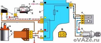
CBKE schemes
Electrical connection diagram for TsBKE on LADA VESTA: 2 – rechargeable battery; 3 – starter; 4 – rear left outer lamp; 5 – left headlight; 7 – rear window heating relay (K3); 8 – right headlight; 10 – rear outer right lamp; 13 – trunk light; 15 – fuse 60 A (F70); 16 – additional relay (K8); 17 – ignition switch; 26 – alarm switch; 30 – fuse 5 A (F20); 32 – left steering column switch (light alarm switch); 34 – fuse 60 A (F75); 35 – rear window heater; 44 – windshield heating relay 1 (K21); 46 – windshield heater; 47 – lampshade lighting of the glove box; 48 – switch for the glove compartment lamp; 51 – TsBKE (VSM controller); 58 – fuse 30 A (F61); 59 – left threshold lamp (installed on luxury equipment); 60 – right threshold lighting lamp (installed on the “luxury” configuration); 61 – relay of additional consumers (K2); 63 – fuse 10 A (F32); 84 – fuse 3 A (F43); 87 – left outside mirror; 88 – right outside mirror; 120 – additional starter relay (K23); 134 – brake signal switch; 138 – fuse 5 A (F15); 164 – air conditioner control panel (connection diagram for the “comfort” package); 185 – interior lighting unit with ERA-GLONASS interface module; 196 – fuse 5 A (F24); 200 – fuse 15 A (F11); 201 – fuse 15 A (F12); 202 – fuse 10 A (F13); 203 – fuse 10 A (F14); 204 – fuse 5 A (F17); 205 – fuse 5 A (F16); 229 – fuse 3 A (F49); 230 – clutch pedal position signal switch; 231 – windshield heating relay 2 (K22); 233 – fuse 5 A (F80)
- location of fuses F1-F59 and relays K1-K20 in the interior mounting block;
- location of fuses F60-F80 and relays K21-K28 in the motor mounting block
Disabling and deleting synchronization settings in 1C Accounting 3.0 and 1C ZUP 3
To disable synchronization, go to Administration – Data synchronization settings and uncheck the Data synchronization checkbox:
These steps should be performed both on the 1C ZUP side and on the 1C Accounting 3.0 side.
Moreover, the synchronization settings themselves are not deleted, i.e. If you check the Data synchronization checkbox again, you will not need to configure synchronization again.
To actually delete synchronization, you need to go to the Administration - Data synchronization settings section, select the desired exchange setting and call the More - Delete synchronization setting command.
The deletion should be performed on both the payroll side and the accounting program side.
Some conclusions
Summarizing the various information reported by Kalina-2 owners on forums, we can draw the following conclusion. No one has any complaints about the operation of the engine, gearbox or transmission, and never had any. Complaints, as a rule, are caused by the quality of the implementation of additional options. Many of which, by the way, can be called excessive luxury for a car of this class. All existing complaints relate only to the blocks and parts that VAZ purchases from suppliers, and not to the main components of the car. There is nothing more to add here.
Prevention
As a measure to prevent breakdowns, experienced specialists recommend periodically performing maintenance on electrical circuits. This requires a complete review of all wires and disconnectors twice a year for damage to the braiding and oxidation of copper contacts. Damaged parts or loose joints must be replaced with new ones.
Also, advice from “experienced” motorists speaks of the rationality of treating parts with special dielectric oil - this prevents air and moisture from entering sensitive areas and significantly increases the service life of devices.
The pinout of panels of the Kalina car from Lada is distinguished by its simplicity and reliability. There are no complex controllers or blocks here. Consequently, system maintenance and troubleshooting do not require in-depth knowledge of electronics or expensive tools.
Lada Granta electrical system: main characteristics
The electrical circuits that supply the engine compartment control systems are designed using a multi-wire circuit and are connected to the vehicle ground only through an electronic control unit.
As a source of energy to power consumers, the standard Lada Granta electrical equipment scheme involves the use of a battery (when the engine is not running) and a generator (when the engine is running).
To connect (switch) the main consumers in the circuit of the Lada Granta car, the electrical equipment is equipped with a combined switch, namely the ignition switch, which in its design consists of a contact part, as well as an anti-theft device.
Basket
Double-glazed window control unit “Norma” 1118 – 6512010 for VAZ 11183 “Kalina”
©Aktuator On cars of the Kalina family, 2 types of non-interchangeable (by wiring) glass control controller 1118 - 6512010 and 11180 - 3763040 can be installed. 1118 – 6512010 has one 25-pin connection connector, 1118 – 3763040 (1118 – 3763040 – 10) – two connectors.
Read also: Owner by car number
Remote control system for double-glazed windows “norm” on a VAZ 11183, Kalina. Controls power windows and central door locking. When the connector is removed, the engine does not start; the device performs some of the anti-theft functions.
Connection
| № | Wire color | Purpose, addressing |
| 1 |
* A regular shock sensor from any alarm system (Alligator, Saturn, Clifford, APS) is suitable.
+ 12 V connect to pin 12; body – on the 6th; We connect the signal wire (a ground appears on it at the moment of activity) to the 1st contact.
During normal arming, Kalina now reacts to an impact on the body (it sounds a horn and blinks turn signals). Similarly, instead of a shock sensor, you can connect a volume sensor (for example, single-level MMS‑1).
You can also connect a pager: + 12 V of the pager transmitter on pin 12, minus on pin 21.
Double-glazed window control unit 1118 – 3763040 (- 10 ) for VAZ 11183 “Kalina”
| External shock or volume sensor input (Not used)* | ||
| 2 | Pink/Black | To the door lock switch in the switch block |
| 3 | Brown/Green | K-Line. To Kl. 71 ECM, Cl. 18 APS‑6 |
| 4 | Brown | Connects to ground when the driver's door is closed |
| 5 | Grey | To rear window heating element |
| 6 | Black | Weight |
| 7 | Pink/White | To the door lock switch in the switch block |
| 8 | Yellow/Blue | In the instrument cluster, to the APS-6 indicator |
| 9 | Black/White | Connects to ground when opening the hood. C VK engine compartment lamp |
| 10 | Two White/Red | Connects to ground when opening the rear doors |
| 11 | Brown/Red | Connects to ground when opening the right front door |
| 12 | Output 12 V power supply for external sensor (Not used)* | |
| 13 | Not used | |
| 14 | Yellow | Pulse + 12 V, closing all doors and trunk |
| 15 | Red/Blue | To class 14 APS‑6 |
| 16 | Blue with Black | To the left direction indicator |
| 17 | Red/Blue | Impulse + 12 V, opening passenger doors |
| 18 | Red/Black | Pulse + 12 V, driver's door opening |
| 19 | Pink/Red | Impulse + 12 V, opening the trunk lock |
| 20 | Yellow/Blue | To terminal “15”, through fuse F 9, in the mounting block |
| 21 | Grey/Black | "-" Horn relay |
| 22 | White/Blue | Connects to ground when the driver's door is opened |
| 23 | Red | To permanent plus through fuse F 5, in the mounting block |
| 24 | Blue | To the right turn signal |
| 25 | White black | Connects to ground when opening the trunk |
| Controller board | ||
| Controller board |
Sign
| Possible reasons | Elimination method |
| The key code is not readable |
1 . 1 Malfunction in the VZ communication coil circuit
1 . 2 Malfunction in the circuit from the block to the communication coil to the APS ECU
1 . 3 Transponder missing in OK
1 . 4 The transponder in OK is faulty (detected during pre-production preparation)
1 . 5 The transponder in the Republic of Kazakhstan is faulty (detected during pre-production preparation)
1 . 6 Malfunction of the input transponder circuit in the APS ECU
1 . 8 The communication coil came off from the VZ pad on the inside
Read also: Ford Explorer 2010
2. 2 Malfunction of W‑Line circuits in the APS or ICS units
2. 3 Lack of supply voltage on the APS or KSUD unit
2. 4 The “Normal” electrical package is faulty (the control driver has burned out)
2. 5 KSUD does not contact
| 1 . 1 - replacement 1118 – 6105006 (set) - rearrange the transponder - rearrange the remote control 1. 2 - replacing the instrument panel harness 1. 3 -replacement of KSUD -replacement of 1118 – 6105006 (set) -replacement of remote control -train the system 1. 4 - rearrange the transponder (if there is a clean one) otherwise: - replace 1118 – 6105006 (set) - retrain the system 1. 5 - replace the remote control - train the system 1. 6 - replace the faulty unit - train the system 1. 7 - replace the remote control with a “clean” one - train the system 1. 8 - replace 1118 – 6105006 (set) - rearrange the transponder - rearrange the remote control | ||||
| 2. 1 W‑Line communication line break | 2. 1 - restore the circuit between unit No. 18 of the APS ECU and unit No. 71 of the KSUD 2. 2 - replace the faulty unit - train the system 2. 3 - eliminate the cause 2. 4 - replace the electrical package - retrain the system 2. 5 - eliminate the leak - replace the control valve - retrain the system | |||
| The read key code is not in the APS memory | 3. 1 - retrain the system 3. 2 - replace the KSUD - replace 1118 – 6105006 (set) - replace the remote control - train the system | |||
| The read key code is not in memory | Revealed during pre-production preparation | 4 beeps IC flashes | The KSUD was previously trained with a different system | — train the system |
| The system is not trained | Security function with remote control on/off, but the internal combustion engine can be started with any mechanical sting (the immobilization function does not work) |
|
Kalina i (2020) e90 “can lin” does not close does not open doors / can and lin interfaces / starline
Good afternoon! I independently installed an E90 alarm with a CAN LIN module on a Lada Kalina 1 (February 2021), software version E90 = L2, CAN LIN version 3.7 Problem: when arming and disarming, the door locks do not close open, nothing clicks or moves at all. At the same time, it correctly reads the status of the doors. The Starline alarm goes off not when the locks are opened (like a standard alarm), but when the door is opened - I don’t know whether this fact is important or not for diagnosing the problem.
The locks work without problems using the standard key fob; the simultaneous opening and closing of all locks using the standard key fob is configured. The SLAVE mode helps out until I switch to an analog connection to the locks.
In the CAN LIN settings, the “standard alarm management” and “central lock control” checkboxes are checked. I unchecked the “central lock control” checkbox, checked that the locks were not working, and checked it again - the locks did not work.
One more point: when setting up autostart, the engine stalled 8-10 seconds after starting, until I set parameter No. 05 of Table 2 - “remote engine start mode” to option No. 2 “without arming” from option No. 1 “with arming” security regime." When disarming after arming for autostart, the first press of the standard key fob button disarms the system, the second turns off the engine, and the third (a few seconds after the second press, otherwise it does not open) opens the doors. I don’t know how correct this work is in SLAVE mode
How can I diagnose my problem in more detail?
If the central locking from the key fob does not work: troubleshooting sequence
Any repair or troubleshooting in a car must begin with checking the fuses that serve a specific system. There are three of them in the diagram below. Usually it can be more. You need to find their location using the car's instruction manual or searching on the Internet.
Video - if the central locking does not work from the alarm, then first check the fuses:
If all fuses are in good working order, proceed to determining the location of the malfunction based on its characteristic symptoms.
Central locking does not close the doors
There are several options for central locking:
does not respond to the key fob signal at all, in this case it is necessary to check, or better yet, immediately change the key fob battery;
does not close the door even with the lock key;
closes and immediately opens the doors.
The last option is associated with loose closure of windows or doors. It is necessary to try to press each door sequentially, supporting it with your whole body, and at the moment of pressing, try to close the central locking.
Perhaps a foreign object has gotten into the closing area of a door; it needs to be checked. You should also check the pressure of the glass so that it fits tightly into the upper grooves.
If the central lock does not respond to the key fob and key, the wires may have broken in the area of the corrugation entering the door. If you have experience repairing electrical wiring, you can find the faulty wire and connect it.
The central locking system does not open the doors, but at the same time closes them
One option is to shift the door hanger. The lock is locked with a door latch. This type of malfunction often occurs in the trunk doors. You have to press them manually to wedge the movement of the lock drive. When you try to open the door, you should hear a click from the drive. In some cars it is almost inaudible; you have to put your ear to the door.
Central locking only closes the driver's door
Here, most likely, the malfunction is a breakdown in communication from the driver's door control unit to the central unit or other doors. You should remove the corrugated hose from the wiring transition from the driver's door to the car interior - there will be a break there.
In some car models, there is a connecting connector at the junction of the wiring into the car interior; you can check its contacts. It is also necessary to examine the electrical wiring under the door trim and all connectors.
One of the doors does not open
Possible malfunctions: damage to the electrical wiring in the corrugation or on the way to it in the cabin, malfunction of the lock drive.
Video - the central locking of the driver's door on a Skoda Fabia does not work:
The lock drive is easy to replace and is inexpensive. During replacement, the main thing is not to damage the levers, rods and plastic tips.
If you replace the central locking drive yourself, to be sure, it is better to find a mechanical diagram on the Internet, reference books, or instruction manual so that you do not forget to install any part.
Devices for diagnostics of electrical equipment
The set of basic diagnostic instruments includes a circuit tester or voltmeter (although it is quite possible to use a banal 12-volt test lamp equipped with a set of connecting wires). If available, you can use an open circuit indicator, which includes a lamp, an independent power source and connecting wires.
In addition, you should always carry a set of cables in your car to start the engine from an alternative source (usually the battery of another car). These wires are equipped with alligator clips.
It would be a good idea to have an electrical circuit breaker, since this equipment can be used to connect circuit elements and bypass electrical equipment during diagnostics.
Malfunctions of electrical equipment in Lada Granta - a guide to action
Although the car has a fairly reliable electrical system that powers consumers, from time to time electrical equipment malfunctions still appear on the Lada Granta.
Before you begin troubleshooting any faults in an electrical circuit, you should carefully study a specific electrical circuit diagram in order to understand the functional purpose of such a circuit as clearly as possible.
Potential fault locations are usually eliminated by identifying and eliminating properly functioning components of the same circuit.
In the event of simultaneous failure of several elements or circuits, the likely cause of failure may well be the blown fuse responsible for these elements. The cause of electrical equipment malfunction in a Lada Granta car may well be a violation of contact with ground.
Failures of electrical equipment are very often explained by the most elementary reasons, among which the most common are:
– corrosion of contacts on connectors; – failure of the safety element; – burnout of fuse links or damage to contact groups and relays.
You should visually check the functionality of all fuses, wiring and connectors in the circuit immediately before proceeding with a more scrupulous check of its components.
If you use diagnostic devices to find a breakdown, plan in detail exactly which points of the circuit circuit and in what sequence (the Lada Granta Norma electrical diagram will help with this) you need to connect the measuring device for more effective detection of the fault.
About the conventions
Let us remember that the practical Lada Granta model went into production back in 2011. This modern car is full of new modifications of complex instruments and electronic devices. All this aims to provide the driver with maximum driving comfort. Today VAZ produces the Lada Granta in three versions in terms of equipment:
The first two options have the same wiring diagram, but in the “Lux” it is different. It's a shame that the factory operating instructions for the car do not contain this wiring diagram. However, do not rush to get upset, because such an album with the entire list of schemes can be purchased in the market network of auto goods.
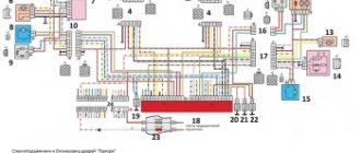
Electrical cabling involves the presence of a large number of bundles. The wiring diagram has symbols and serial numbers, each of which is assigned to a strictly specific pantograph. These consumers in the diagram are switched into the general network via conventional lines. To increase clarity, the developers used different colors for the lines. Next, the wires are assembled into bundles, which are connected to electrical units using special connectors.
The first number in the wire marking indicates the plug, connector or terminal to which this cable is connected. The number present behind the fraction sign indicates its correspondence to the contact number of the pantograph.
The reader can familiarize himself with the operating principle of a particular electronic unit on his own. If the defects are minor, then they do not create difficulties during the repair or replacement process. But the situation changes when a complex component fails, which implies the need to turn to electricians. To understand the situation with a malfunction of a specific pantograph, the owner of a LADA Granta does not need to remember all the details and details of the layout drawing, but it will be enough to know the location of the device and the features of the wiring leading to it.
Information about techniques that allow you to quickly replace a fuse or relay that has become unusable will also be useful. The Lada Granta mounting block provides backup fuses and relays of the same nature. Safety elements are necessary to protect circuits from current overloads, which lead not only to failure of the device, but also protect the circuit from short circuits, which pose a risk of subsequent fire. In such a situation, the fuse-link heats up, after which its element burns out, thereby cutting off the power supply to the pantograph. Fuses may only be replaced with analogues set to the same maximum current. Neglecting this important rule can also cause breakdowns and fires.
Seats: too dirty upholstery and everything that follows from this
In the configurations of Luxury cars, starting from the 1st generation of cars, fabric was used for seat upholstery, which was too classy. VAZ was supposed to solve this problem in the spring of 2014. The new fabric, oddly enough, ended up not being much better than the old one. Advice from experienced people: you need to put covers on the seats.
Structure of the new upholstery fabric designed for luxury trim levels
By the way, leather cases conduct heat very poorly. In trim levels where heated seats are provided, there is no point in using such a solution - heating will proceed very slowly. The owner should be aware of this so as not to waste a significant amount on an expensive and useless addition.
Let's ask ourselves how much of a brand the fabric of the standard upholstery actually is. If we talk about difficult operating conditions, then, according to reviews, you have to clean the seats once every six months. Make a choice.
general information
On machines equipped with Norma, central locking control units are installed, which are replaced with new ones if they break down. On Luxe vehicles, TsBKE are used instead. Below we will try to take a more detailed look at the central locking unit and its control unit, their relationship with the remote control, symptoms of a malfunction of this part, and also provide instructions for replacing it yourself.
Now let's look in more detail at remote control, which is intended not only for locking and unlocking car doors at a distance with synchronous activation of the security mode. In addition, it allows you to lock all locks with one turn of the key, lock and unlock all door locks by pressing one button located inside the cabin, and also turn on and off the car alarm both remotely and with the key.
Operating modes
Door locks on Grants are blocked by pressing the corresponding key on the remote control, after which they can be unlocked using the remote control in stepwise and simultaneous unlocking modes. The first of the listed modes will allow you to unlock all door locks by double pressing the key (first the driver's door is unlocked, and then all other doors). When you activate the second mode, you can unlock all the doors of the car at the same time, with one click.
Read more: A crab vomited on a VAZ 2109, what to do?
To change the mode, the car owner will need to perform the following steps:
- first you need to turn on the ignition with the remote control key;
- then you will need to press and hold the unlock and lock keys in this position for five seconds;
- After the buzzer sounds, release the keys.
Blocking
If, after unlocking the door locks, you do not open the trunk or one of the doors, or do not turn on the ignition, then after twenty-five seconds all doors will be locked again.
Control from the cabin
When blocking doors directly from inside the car, you need to press the corresponding button located on the driver's door, or press a similar button in the module of the same door. Unlocking will require lifting the desired key on the door or pressing it in the module. To lock the doors from the outside, you will need to turn the key in the lock located on the driver's door clockwise, and to unlock the doors, turn the key in the opposite direction.
Window control
By pressing and then holding the lock button in this position for three seconds, you can raise the lowered door windows, with the front windows going up first, followed by the rear door windows. By pressing and holding the unlock key for three or more seconds, you can lower the raised windows in a similar sequence.
Opening the trunk
Unlocking the trunk lid lock on a Grant using the remote control is possible only after turning off the ignition. So, when opening the lid, you must either press the key on the remote control twice, with a minimum interval, or press it once, but hold it down for at least several moments. When the security mode is activated, the trunk will open synchronously with the security zone being turned off for at least half a minute. To close the lid you will need to slam it shut again.
Personalize existing features
The manufacturer has provided for the timing of regular technical inspections, which are mandatory. For non-compliance, the company reserves the opportunity to deprive the car owner of the right to free service.
The most vulnerable is the comfort block, which includes many logical circuits. Its purpose boils down to the following functions:
- activation of interior lighting;
- adjusting the operation of car alarms;
- turning on the heated rear window;
- automatic mirror adjustment;
- control of electric windows;
- remote control of locks.
The manufacturer has provided the ability to personalize each element. To do this, the electrical package control unit must be recoded at an authorized automotive center. Using official software, the wizard will add or remove certain features. If everything is done correctly, 20 minutes after requesting the appropriate service, you can safely use the “iron horse”.
According to reviews from car enthusiasts, the Lada Kalina car is distinguished by electronic filling with increased sensitivity to operating conditions. Aggressive driving style and minor damage lead to malfunctions.
As a result, you need to visit a service station to replace the device. To do this, remove the control unit, which must be done as follows:
- turn off the battery;
- unscrew the screws from the driver's seat;
- Use a ratchet wrench to remove the nut;
- the plastic plug is squeezed out completely;
- carefully pull out the seat;
- remove the seat by dismantling the terminals;
- remove the cover plate.
The replacement procedure on the Kalina 2 model is completed by folding the carpet and installing a new block. After this, all procedures are carried out in reverse order.
Steps from “Norma” to “Lux”. Part 1. — Lada Kalina Sedan, 1.6 l., 2006 on DRIVE2
Good day, FRIENDS.
It all started when I broke the passenger rear view mirror. And since I never liked them, this is an excellent reason for Tuning))
I chose mirrors from Granta Liftback, with electric drive, heating, and collars.
Mirrors.
To connect the electric drive I decided to use the ESP control unit from Kalina Lux
ESP control unit
I know that there are extra hemorrhoids, and that it could have been done simpler. BUT! I want to do everything well, as close to standard as possible! Well, rear windows are planned in the near future! But as it turned out, this block communicates with the comfort block via one wire, which is not supported by the comfort block from Norma. I decided to replace the standard block with a block from Lux. They have different connectors, which means you will have to redistribute the contacts. After reading the Internet I found these diagrams.
Comfort Block Diagram Standards
Full size
Luxury Comfort Block Diagram
XP1 1st - ? — New — To the ESP engine of the front-right door. 2nd - ? — New — +/- on all doors. 3rd - Yellow - from pin 14 - To the motors for closing all doors (to all doors). 4th - Orange-Black - New - to the ESP engine of the rear-right door. - No need for a while. 5th - Red-Blue - from the 17th contact - opening the passenger doors. 6th - Black - from the 6th contact - To Ground. 7th - ? — New — to the ESP engine of the rear-left door. - No need for a while. 8th - Blue - from pin 24 - Control of starboard turn signals. 9th - Red - from pin 23 - to terminal 30 (+12V?) 10th - Reserved 11th - ? — New — +/- in the driver’s and rear left door and trunk. 12th - Black - wire from pin 6 - To Ground. 13th - Green-black - New - connect the ESP of the front-left door to the engine. 14th - Blue-Black - from the 16th contact - Control of the left side turn signals. 15th - Red - from pin 23 - to terminal 30 (+12V?)
XP2 1st - Pink-Red - from pin 19 - to the trunk opening motor. 2nd - Reserve 3rd - ? — New — To the power window button of the Rear-Right door. - No need for a while. 4th - White-Black - from pin 25 - Trunk opening limit switch. 5th - ? — New — Passenger mirror up and down. 6th - Red-black - from pin 18 - Opening the driver's door. 7th - Brown-Red - from the 11th contact - Front right door limit switch. 8th - ? — New — Illuminated power window buttons. 9th - ? — New — Passenger mirror left and right. 10th - Red-Blue - from the 15th contact - K-Lin bus. 11th - ? — New — ESP button for the front-right door. 12th - ? — New — ESP button for the rear-left door. - No need for a while. 13th - Gray - from the 5th contact - Heated rear window. 14th - Reserve 15th - Reserve 16th - White-Red - from the 10th contact - Opening the rear doors. 17th - Reserve 18th - Black and White - from the 9th contact - Opening the hood. 19th - Reserve 20th - to the siren - No need.
XP3 - Not used
Attention Questions: - Has anyone ever engaged in such masturbation? Or am I the first to decide on this? — In the diagrams there is a reference to Terminal 30, does anyone know what kind of terminal this is? I'm guessing it's a constant +12V, am I right? — The normal unit is connected to terminal 71 of the ECM/terminal 18 of the APS, but the Lux unit does not seem to be connected to the controller at all, or am I missing something? — The normal unit was connected to the instrument cluster (Terminal 8), but the Lux unit is not connected to the combination at all, do I need to connect it and where? — The standard unit has an output for the rear window heating relay, but the luxury unit does not, will it work? Or how is control implemented in Lux? — If anyone can help with the color palette in the lux connector, I would be grateful