Removing and disassembling the ignition switch
We remove the ignition switch to replace its assembly, as well as to replace the contact group of the switch or the APS coil.
Disconnect the wire terminal from the negative terminal of the battery. We remove the steering column switches (see “Removing the steering column switches”). The heads of the ignition switch mounting bolts are cut off. That's why.. . Unscrew them using a chisel. Loose bolts can be removed using pliers.
Remove the bracket from the steering column.
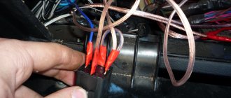
. and the ignition switch. Use a slotted screwdriver to pry up the clamp of the APS coil wire block.
. and disconnect the coil wire block from the APS block wire block.
Pressing the pad lock. ..disconnect the ignition switch contact block from the wiring harness block.
Using a Phillips screwdriver, unscrew the three screws.
. and remove the ignition switch bracket.
We take out the locking rod of the anti-theft device. Turn the key in the ignition switch.
. and remove the locking rod drive. Remove the rod spring from the drive.
. and a stopper with a spring. Push the cylinder out of the switch body.
. and remove the locking ball.
Remove the cylinder from the switch body.
We remove the locking ball spring from the hole in the cylinder.
Prying it with a screwdriver. ..we disengage the two plastic latches of the wire block cover.
. and open the lid. We mark the wires located in the block.
Using a thin awl or stiff wire, bend the locking tendrils of the wire tips.
. and remove the wires from the block.
Remove the insulating tube from the wires.
Squeeze the three plastic latches with a screwdriver. ..remove the contact group from the body.
. and bring the wires out through the holes in the housing.
Prying it with a screwdriver. . disengage the three plastic latches.
. and disconnect the contact group.
Remove the moving part of the contact group.
By pressing the moving contact and turning it counterclockwise.
. remove it from the body.
Remove the contact spring.
. remove the APS coil. We assemble and install the ignition switch in the reverse order. We install the moving part of the contact group as follows.
. so that the wide protrusion of the moving contact is located opposite the protrusion on the cover with the fixed contact. . and the protrusion on the lock cylinder should fit.
. into the recess on the body of the moving part of the contact group.
Tool:
- Multimeter
- Chisel
- Large hammer
- Narrow nose pliers
- Straight box spanner 10 mm
Parts and consumables:
- Tear-off bolts (4 pcs.)
In the power supply circuit for most of the vehicle's electrical equipment, except for the emergency, sound and light alarms, the canopy lighting, side lights, the brake signal, the security alarm and the electric door locks, voltage is supplied through the ignition switch.
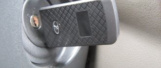
To increase the car's anti-theft properties, the switch is combined with a lock, which is why this device is more often called an ignition switch. The lock body is attached to the steering column with four special bolts with break-away heads.
At a certain tightening torque, the bolt heads come off, and after that it becomes impossible to unscrew the bolts with wrenches.
The ignition switch is additionally equipped with a steering shaft locking mechanism. Once the key is removed from the lock, the spring-loaded latch is released. When you try to turn the steering wheel, the latch locks the steering shaft from turning.
General diagram of electrical equipment of VAZ 1118
1 — block headlight; 2 — windshield wiper gear motor; 3 - generator; 4 - battery; 5 - starter; 6 — sound signal; 7 — hood open sensor; 8 — power window switch for the right front door; 9 — motor-reducer for window lifter of the right front door; 10 — electric pump for windshield washer; 11 — connecting blocks of wires for connecting the right (front) speaker of the audio system; 12 — electric drive for locking the lock of the right front door with an open door sensor; 13 — ambient air temperature sensor; 14 — connecting block of the wiring harness for connection to the engine control system harness; 15 — electric drive for locking the left front door lock (with an open door sensor and a central locking switch); 16 — sensor of insufficient brake fluid level; 17 — connecting blocks of wires for connecting the left (front) speaker of the audio system; 18 — right front door power window switch (installed on the driver’s door); 19 — left front door power window switch; 20 — central locking switch; 21 — motor-reducer for window lifter of the right front door; 22 — remote control unit; 23 — immobilizer control unit (APS-6); 24 — mounting block; 25 — instrument panel; 26 — right side turn signal; 27 — glove box lighting lamp; 28 — switch for the glove compartment lighting lamp; 29 — brake signal switch; 30 — ignition switch (lock); 31 — lighting control unit; 32 — steering column switches; 33 — left side direction indicator; 34 — connecting blocks of wires for connecting the left (rear) speaker of the audio system; 35 — electric drive for locking the left (rear) door with an open door sensor; 36 — electric heater fan; 37 — additional heater resistor; 38 — heater switch; 39 — alarm switch; 40 — reverse lock solenoid switch; 41 — rear window heating switch; 42 — connecting blocks of wires for connecting the right (rear) speaker of the audio system; 43 — electric drive for locking the right rear door lock (with a door open sensor); 44 — fuel module of the engine control system; 45 — reverse light switch; 46 — parking brake warning lamp switch; 47 — cigarette lighter; 48 — reverse lock solenoid; 49 — connecting blocks of wires for connecting the head unit of the audio system; 50 — backlight lamps on the trim of the center console of the instrument panel; 51 — electric power steering control unit; 52 — interior lamp; 53 — rear light; 54 — block for connecting the electric drive for locking the trunk lid lock*; 55 — luggage compartment lid open sensor; 56 — license plate lights; 57 — additional brake light; 58 — rear window heating element; 59 — luggage compartment lighting lamp.
Design
The lock consists of mechanical and electrical parts. Briefly about the design of each of them:
- The mechanical part is a cylindrical mechanism, which can only be turned with a key designed specifically for it. In addition, this includes an anti-theft latch that prevents the steering wheel from turning.
- The electrical part consists of terminals and contacts that close accordingly with each turn of the key. For this purpose, it is connected to the lock mechanics. There are only three contacts. One of them, the thirtieth, is supplied with plus directly from the battery. The remaining two (15 and 50) are intended to turn on consumers and the starter, respectively. To limit the current through the fiftieth contact, a relay is included in its circuit. The starter is powered through its contacts, and not through the Kalina ignition switch.
The immobilizer antenna is located in the decorative ring covering the 3Z. It responds to the transponder of the key inserted into the lock. The immobilizer recognizes only its own unique signal and gives permission to the control unit to start the engine.
Key programming instructions for Lada Kalina, Priora, Granta, etc.
- Close all doors. Turn on the ignition with the training key and wait in the on state for at least 6 seconds.
- Turn off the ignition. The indicator light in the warning lamp unit should flash quickly (at a frequency of 5 times per second) while the learning procedure is being carried out correctly. If the lamp stops flashing quickly, it indicates an incorrect operation, an out-of-time interval, or a malfunction. Remove the training key from the ignition switch.
- While the warning lamp is flashing (about 6 seconds), insert the remote control and turn on the ignition. The immobilizer buzzer should emit three sound signals. If the buzzer does not sound and the flashing indicator stops, this means: - the time interval of 6 seconds has been exceeded and it is necessary to repeat the learning procedure, starting from step 1; - the immobilizer is faulty
- Wait 6 seconds for the buzzer to emit two more beeps and turn off the ignition.
- If it is necessary to train the second remote control, then you should perform steps 3...4 again, using the second learning remote control to turn on the ignition. If not, continue from step 6.
- After turning off the ignition for no more than 6 seconds, while the indicator is flashing, remove the remote control, insert the learning key and turn on the ignition. The buzzer should beep three times. Wait 6 seconds until the buzzer beeps two more times.
- Turn off the ignition without removing the training key, wait 6 seconds until the buzzer sounds a single sound signal. The indicator should flash twice as fast. If the sound signal does not sound and the flashing of the indicator stops, you should return to step 1 and repeat the learning procedure. If a repeated failure occurs when performing step 7, this means that the ECM was previously trained with a different key, in which case the controller should be replaced.
- After the buzzer gives a single sound signal, no later than 3 seconds, turn on the ignition for 2...3 seconds and then turn it off (after turning on the ignition, the buzzer will sound three times and the indicator will stop flashing). The hazard warning lights should flash and the car signal will “beep”.
- Remove the learning key. Wait with the ignition off for at least 10 seconds. Insert the working key and turn on the ignition. Wait 6 seconds, if the indicator does not flash, test start the engine, the engine should start. If the indicator flashes, turn off the ignition and wait at least 10 seconds. Turn on the ignition. The warning light should not blink, and the engine should start. If after turning on the ignition, after 6 seconds the warning light comes on with a constant light, then the learning procedure must be repeated, starting from step 1.
ZZ malfunctions
Most often, damage to the Kalina ignition switch is associated with its mechanical part. In this case, it is impossible to turn the key to the desired position. A malfunction does not arise, as they say, out of the blue. As a rule, frequent jamming of the key is observed over the course of several months, which is eliminated by rocking it in the cylinder.
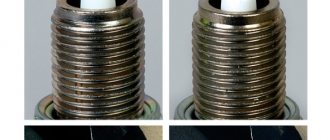
Rarely, there are cases of failure of the electrical component of the Lada-Kalina ignition switch. Basically they come down to a lack of contact when turned on. This is typical only for locks with a long service life. True, there is another common reason for burnt contacts - the car owner himself.
When installing additional equipment, the owner of the car does not take into account that the maximum permissible load on contact is 15, only 19 amperes. This is quite enough for regular consumers, but the lock can no longer withstand additional light and sound devices, especially those installed at home. The contacts begin to spark and eventually fail. Therefore, when installing additional equipment, it is necessary to use an additional relay to power it.
General information
The purpose of the Kalina ZZ is no different from other cars - turning on the ignition and controlling the engine starter. It is equipped with a mechanical interlock and protection against restarting the starter without turning off the ignition. This allows you to protect the flywheel crown and bendix from accidental turning of the key. There is also electronic protection in the form of an immobilizer, the antenna of which is integrated into the 3Z.
The Kalina ignition switch has 3 positions, each of which is described in the table.
Side lights, radio, hazard warning lights, brake lights, courtesy lamp
Car ignition system, low and high beams, heater, washer and wipers, turn signals, fuel pump.
The key can only be pulled out in the zero position. In order not to forget it in the lock, when the engine is turned off, an audible alarm is provided, which turns on simultaneously with the opening of the driver's door.
Symptoms of a problem
The main symptoms of 3D damage are most often obvious:
- The Kalina ignition key does not turn. You should not think that it can only jam in the “0” position. Sometimes, on the contrary, the car cannot be turned off because the key does not return to the neutral position.
- A number of devices do not work, including the indicator lamps on the panel do not light up.
- The starter does not turn.
- There are constant interruptions in movement, with the disappearance of readings from control devices.
- The instrument panel lamps light up after several turns of turning the key in one direction or the other.
Training procedure
Carrying out the training procedure leads to the following consequences:
- the engine control controller activates the anti-theft function if it has not been activated;
- the system changes its password to a new one chosen at random;
- a new system password is written into the training key;
- all remote controls that were previously trained are erased from memory;
- The codes of those remote control units that were trained in this training procedure are stored in memory.
The training procedure is applied in the following cases:
- activating the anti-theft function in the controller (for example, in a new car or replacing a faulty controller);
- erasing old and training new remote controls if lost;
- changing the system password if the owner admits that his system password may have been read (for example, when selling a car from one owner to another)
- remote control training when replacing a faulty immobilizer with a new one.
Only new remote control units or those that were previously trained using the training key used in this training procedure can be trained. It is impossible to learn a remote control key from another car into your car.
Please note: Due to the importance of the training key, it is not recommended to use it for everyday use and should be kept in a safe place. Before starting the training procedure, fill the car with at least 10 liters of gasoline, so as not to get confused by squeaks
Before starting the training procedure, fill the car with at least 10 liters of gasoline so as not to get confused by the squeaks.
Repair or buy a new one
There is no clear answer to this question. The fact is that it is very difficult to find a new contact group on the Kalina ZZ, in contrast to the classics, Samara and the tenth family. Therefore, you have to repair it, which without experience, skills and desire is not the best idea. Most often, owners install a new ZZ by purchasing it assembled.
In this case, it is necessary to take into account that the Kalina ignition switch has an immobilizer that will not respond to the new key and the car will not be able to start. Of course there is a way out. You can retrain the immobilizer for a new key. In this case, you will also have to change the cylinders on the door locks.
You can do it easier - carry two keys with you. True, it is not clear whether it is worth keeping them on one bundle. Therefore, the most reasonable thing would be to make a new “tip” and install it on the old key. By the way, it may be included in the delivery of a new lock.
About installing the larva
The lock is broken, does not allow the car to start, does not turn at all or turns with difficulty, the key is stuck in the hole. All this suggests that the ignition switch cylinder needs to be repaired. Perhaps the problem will be solved with simple lubrication.
It is enough to use contact cleaner. Even the one designed for battery terminals will do. This is a very effective remedy. For repairs, the mechanism must be disassembled. Removing the larva is not easy. Sometimes it is necessary to remove the retainer using a rough mechanical method. When the element is removed, the cylinder is easily removed from the lock body.
Replacing the ignition switch
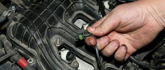
As always, if the work involves electricity, you need to start by disconnecting the negative terminal of the battery. The tool you will need is a shaped screwdriver and a small chisel. You must purchase an ignition switch in advance. In this case, you need to take into account the presence of an immobilizer. If everything is ready, you can proceed to replacement. The sequence of actions is as follows:
- After unscrewing the five bolts, remove the decorative steering column cover. The screws are different, so it’s better to remember which one was placed where. In addition, to remove the casing, you need to lower the steering column adjustment knob.
- The ignition switch is secured to two clamps, secured with bolts that cannot be unscrewed with a key. Therefore, you will have to use a chisel. You need to rest it against the cap and unscrew it with careful but rather strong blows until it becomes possible to do it with your hands. That is, you should not cut off the bolt with a chisel, but use it as an analogue of a key.
- Thus, you will have to unscrew all 4 screws.
- The lock will remain hanging on the wires.
- We disconnect the electrical connectors, and the ignition switch can be easily removed.
- Installation is carried out in reverse order.
It is worth noting that this sequence of actions is similar for all modifications of the car, including the ignition switch of the Kalina 2, produced since 2013.
How to disable the immobilizer with your own hands?
There is an option to temporarily disable the immobilizer, which may be required when installing an alarm system with auto start.
To install the bypass system, use:
- A control unit with a key or tag embedded in it. A key or chip is inserted into a device located deep in the dashboard. When autostart is activated, the alarm relay activates the unit and the engine starts, bypassing the main circuit.
- Blockless immobilizer bypass unit. A separate control device is installed that emulates an ignition key with a chip.
Another way to disable the immobilizer on Kalina depends on the type of ECM (control unit).
Bosch M7 4 block
Before you begin performing an operation on a car with a Bosch M7.4 unit, you must prepare:
- a computer or laptop with Winflashecu v.1.14 preinstalled (the distribution is available for free download);
- adapter and cord K-Line, for example, VAG-COM 409.1;
- pre-downloaded software for the unit with disabled immobilizer support;
- several wires with different lengths.
To disable the immobilizer on Kalina, you need to perform the following steps:
- Remove the wires from the battery terminals and disconnect the wiring harness connectors from the ECM installed under the hood of the vehicle. To disconnect, you need to remove the protective top cover and pull out the flat connector lock. All work is carried out on a large block. The small block can not be disconnected from the block.
- Insert the wire into contacts A4 and B2 from the harness side. These cables will be used to supply additional 12 V positive voltage. To do this, they are connected to the battery terminal through an intermediate switch.
- Reinstall the connector and fasten the fastener.
- Connect the adapter to the diagnostic connector located in the passenger compartment. The connector is located under a plastic cover installed on the center console.
- Set the data transfer rate to 38400 bps in your computer settings.
- Launch the Winflashecu application and select the port number, speed (38400 bps) and block type M7.4 in the dialog box. In the lower right corner of the window there will be a message “No connection”.
- Apply additional power to pins A4 and B2.
- Turn on the ignition. The “No communication” notification should change to “Communication with the ECU” and the buttons for starting operations will become active.
- Read the EEPROM (unit software) data and save it to the computer's hard drive.
- Select new software and load it into the unit’s memory using the “Write EEPROM” button.
- Wait for confirmation that the download was successful.
- Close the program and turn off the ignition.
- Remove the auxiliary power wires.
- Check whether the car can be started with a key without a chip. The immobilizer symbol will light up in the instrument cluster when starting and go out after a few seconds.