Design Features
VAZ 2109 cars can be equipped with two models of generator units. These are 37.3701 and 9402.3701.
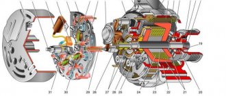
Description of the structural elements of the first:
- 1 — clamping fitting;
- 2 - bushing;
- 3 - buffer fitting;
- 4 — rear cover of the unit;
- 5 - bolt fixing the rectifier device;
- 6 - the rectifier unit itself;
- 7 - valve of this device;
- 8 - capacitor component;
- 9 — rear bearing element of the rotor shaft;
- 10 — slip rings;
- 11 — pulley of the rotor device;
- 12 - brush connected to terminal B of the regulator;
- 13 — contact 30, necessary for connecting energy consumers;
- 14 — contact element 61 of the generating set;
- 15 - brush connected to output Ш on the control mechanism;
- 16 - contact B of this element;
- 17 — the voltage regulator itself in the on-board network;
- 18 — pin for fixing the generating set to the tension bar;
- 19 — impeller;
- 20 - shaft;
- 21 — washers for fixing the bearing device;
- 22 - thrust ring;
- 23 — front bearing element of the rotor device pulley;
- 24 — rotor winding;
- 25 - pole piece of this device;
- 26 - another winding;
- 27 — stator mechanism;
- 28 — front cover of the generator unit.
Diagram of device model 37.3701
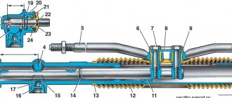
Design of unit 9402.3701:
- 1 — protective casing of the device;
- 2 — contact B+ for connecting the electrical equipment of the machine;
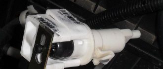
- 3 - capacitor device;
- 4 - common contact of additional diode elements. It connects to the D+ output on the control fixture;
- 5 — fixing device for positive diodes of the rectifying mechanism;
- 6 — clamp for negative diode elements;
- 7 - positive diode;
- 8 - negative element;
- 9 — voltage regulator in the machine’s electrical network;
- 10 — rear cover of the generating set;
- 11 — coupling bolt;
- 12 — front cover of the generating set;
- 13 - stator winding;
- 14 - thrust ring;
- 15 — front bearing element of the rotor mechanism shaft;
- 16 - shaft;
- 17 - nut;
- 18 — shaft of the rotor mechanism;
- 19 — cone-shaped washer;
- 20 - regular washer;
- 21 — pole pieces of the rotor mechanism;
- 22 — core of the stator device;
- 23 - bushing;
- 24 — winding of the rotor mechanism;
- 25 — rear bearing element of the rotor pulley;
- 26 — bushing of the bearing element;
- 27 — slip rings;
- 28 — brush assembly holder;
- 29 — contacts of the stator mechanism winding;
- 30 - additional diode element;
- 31 - common contact D.
Design of the generator 9402.3701
Carburetor power units are equipped with devices model 37.3701, and injectors - 9402.3701. These units are similar in design; they are synchronous AC motors. They are equipped with a built-in rectifier unit based on silicon diode elements. And the voltage regulator in them is electronic.
On vehicles built before 1996, 37.3701 models used separate adjusters and brush holders. In such devices, the voltage from pin 30 was supplied to pin B. In later versions, this parameter is supplied to pin B, since B is absent.
Why is a generator needed?
It is needed to power the on-board network when the engine is running. When stopped, the entire network is powered by a battery. If you yourself replaced the VAZ-2108 generator or any other car, you saw that it has one power terminal. Several wires are connected to it:
The thickest one connects the generator to the positive terminal of the battery. It is through this wire that the battery is charged.
Please note that there are no fuses on it. Therefore, during any manipulations with the generator, it is necessary to de-energize the on-board network. A thin short wire going to the voltage regulator is necessary to power the excitation winding. It is rare, but it happens that additional equipment is connected to this output of the generator.
The cars use a rather old but proven design of the VAZ-2108 generator. The carburetor is used in the fuel injection system. On injection cars, fuel injectors and ignition coils are powered from the power output of the generator. All other consumers take power from the positive terminal of the battery.
How to check for serviceability?
Before diagnosing problems with injection and carburetor cars, you must start the engine and let it run for a few minutes. Then, pressing the gas pedal, you need to increase the number of crankshaft revolutions to 3 thousand/min.
To create a simulation of driving in normal mode, enable:
- driving lights;
- rear window heating systems;
- stoves.
Diagnostics with a multimeter:
- The tester is used to measure the voltage at the battery terminals. This parameter will be 13.2 volts in model 9402.3701 and 13.6 V for 37.3701. If, during diagnostics, without removing the voltage at the battery terminals, the obtained value turns out to be different, this indicates a break or short circuit in the windings of the device. The voltage regulator and brush assembly may also fail. Sometimes the problem is oxidation of the contact components of the field winding.
- To ensure that the regulatory mechanism is working, all energy consumers are switched off. Only the high beam optics remains switched on, after which the voltage measurement procedure is repeated. This parameter should be in the range from 13.2 to 14.7 volts for model 94.3701. In the 37.3701 electric generator, the resulting value will be from 13.6 to 14.6 V.
- If the control element on model 9402.3701 is removed, it can be checked by connecting a light source to the brush mechanism. In particular, between its elements. The lamp should be rated at 1-5 watts and 12 volts. The DC power supply is connected to the D+ pins and device ground. Diagnostics is performed first by activating the voltage at 12 volts, and then at 15-16 V.
- In the first case, the light source should work, but in the second, it should not. If it is activated when 12 and 15 volts are supplied, then a breakdown must be looked for in the regulatory device. If there is no combustion, the cause should be checked for a break or broken contact between the brush elements and the terminals of the device. The regulator itself is changed to restore the generator's functionality. To test the device 37.3701, the light bulb is connected to contacts B and C, this is a plus, as well as to ground.
- Checking the valves of the rectifier device is carried out by disconnecting the cables from the battery, generator unit, and also the regulator contact. The positive terminal from the battery is connected through a light source to the B+ output on the generator device 9402.3701. If this is model 37.3701, then it must be connected to output 30. The negative contact is ground, connected to the housing. If, as a result of the actions performed, the light source started working, then the problem is a short circuit (in both blocks).
- Diagnosis of a similar problem on positive valves is carried out by connecting the positive contact of the battery to the B+ output (for model 37.3701 - contact 30). The connection is made through the light source. The negative contact goes to the output of the phase winding of the stator mechanism (you can connect to any). The inoperability of one or more positive valves will be indicated by activation of the light bulb.
- The procedure for diagnosing a short circuit on the negative contacts of the element is performed by connecting the positive terminal of the battery to the phase winding of the stator mechanism. There should be a light bulb on the electrical circuit, and the negative terminal goes to the housing of the generator set. If the lighting device lights up, this indicates damage to the negative valves or a short circuit of the stator mechanism to the body of the automobile electric generator.
- To prevent short-circuiting of the windings, the assembly is dismantled from the machine, after which the elements are disconnected from the regulator and the rectifier unit. Using a light source or an ohmmeter, parts are checked for short circuits. The valves of the generator device can be diagnosed with a tester; this does not require connecting a battery or a light bulb.
- To check additional diode elements, the positive terminal of the battery is connected to output D through a light source. In model 37.3701, the connection must be made to pin 61. The negative terminal goes to the output of one of the phase windings of the stator device; you can use a screw to secure the rectifier assembly. If the light source lights up, this indicates damage to the diode elements.
- To determine whether the valves are broken, you need to check the output current; this parameter should not fall as a result of the load. But such a problem may be caused by damage or short-circuiting of the windings of the generator unit.
- To diagnose each diode element, you will need a tester or test light. To do this, the rectifier assembly will have to be dismantled. If this device breaks down, it must be replaced as an assembly. It is possible to replace individual valves, but the main elements require re-pressing in the holding device. Performing this operation requires caution and skill from the car owner.
The windings of a stator or rotor mechanism can only be diagnosed using a flaw detector or electronic oscilloscope; the test consists of monitoring voltage curves.
The “Avto-blogger” channel described in detail the procedure for examining a car’s generator unit.
Possible faults
If the node does not work or functions incorrectly, you need to find the cause of the problem:
- When the ignition is activated, the indicator light on the dashboard does not light up. Perhaps this symptom was caused by a faulty fuse. The problem may be damaged wiring. It is necessary to check the electrical circuits and safety devices. Wiring testing is carried out using a tester.
- The LED indicator on the device does not light up, but the battery is discharged, all other control devices are working normally. A possible problem is a short circuit of the diode elements on the bridge or poor contact on the excitation winding. The cause of the problem may be a malfunction of the relay, failure of the brush mechanism, or damage to the wiring from the generator to the dashboard. All failed components can be repaired or replaced yourself.
- The battery indicator light on the dashboard lights up when the engine is running, the battery may be overcharged. It is necessary to diagnose the regulatory device; the problem may lie there.
- When the car engine is running, the battery indicator lights up too brightly or only at 50%. It is necessary to diagnose the drive belt; the problem may be that it is worn out or weakened. To eliminate the malfunction, the belt must be tightened or replaced. The reason may be a short circuit of the stator winding to ground or damage to the electrical circuit. Sometimes the reason lies in faulty diodes or disconnection of the rotor mechanism from the slip rings.
- A whistle comes from under the engine hood. The noise may appear when the power unit is started and disappear after a few minutes, or it can be heard constantly. The problem is due to wear on the drive belt. This product must be replaced.
- A strong hum-like noise may indicate a worn generator set bearing. Sometimes this symptom is associated with a short circuit of the stator winding to ground or a short circuit of one of the diodes.
- At night, when the optics are activated, you can see that the headlights burn dimly. But when you press the gas pedal, their brightness is restored to the required level. The voltage regulator device needs to be checked.
Channel “Tora 18” talked about the main malfunctions typical of automobile generator sets.
Generator faults
The most common generator malfunctions are:
- Damage to the pulley (see Replacing the VAZ 2109 generator pulley on your own). It is quite durable, so it does not need to be replaced too often. However, its failure leads to the failure of other parts.
- The current collection brushes are worn out.
- The collector is worn out. It cannot be repaired in such cases. Only needs replacement.
- The voltage regulator has been damaged due to improper use.
- The turns of the stator winding are closed
- The bearing is worn out or completely destroyed.
- The rectifier is damaged.
- The charging circuit is broken. By the way, it breaks very easily, so when working with it, you need to be very careful.
Two main types of faults
Since the generator is an electromechanical device, two types of faults can be distinguished:
- Mechanical. These are: destruction of the housing, various fasteners, improper operation of bearings, loss of elasticity of springs. That is, such damage is not related to electrical failure.
- Electric. Such malfunctions most often include: winding breaks, poor performance of the diode bridge, brush wear, breakdowns. That is, such damage does not appear due to mechanical impact.
Signs of trouble
VAZ 2109 generator does not work
You can tell that the generator is broken by the following signs:
- While the engine is running, the battery discharge lamp either flashes or does not light up correctly.
- The battery is either always discharged or overcharged (liquid boils away).
- Car headlights are less bright than before.
- The signal is played at a lower volume. By the way, the cause of this may also be a jammed signal button, so there is no need to jump to hasty conclusions.
- There are strange sounds coming from the generator that were not there before. Perhaps they resemble a squeak, howl, or hum.
https://youtube.com/watch?v=XB0LZTRJ_Y0
Causes of malfunctions
VAZ 2109 generator no charging
The most common causes of malfunctions are:
- Wear of its parts.
- Corrosion. It is because of rust that many parts fail. Their mobility and plasticity decrease, and over time they completely collapse.
- Long-term operation of parts. Nothing lasts forever, in fact, just like the components of the generator.
- The quality of the components was initially low. Therefore, when purchasing, you need to look at what exactly you are buying.
- Operation was not carried out in accordance with the necessary requirements.
- Also, generator malfunctions can occur due to external influences.
Some causes of generator malfunction can be eliminated with your own hands. Others require only the intervention of a master. The price for repairing a generator at a car service center is much higher than what you would have to pay if you did the repair yourself. But without the necessary knowledge, it is better not to stick your hands on your “swallow”. Therefore, before starting the repair itself, it is worth reviewing photos and videos on this topic. The instructions will also not be superfluous.
How to repair it yourself?
The restoration procedure consists of several stages:
- First you need to dismantle the unit.
- Then it is disassembled, at this stage the unit needs to be repaired.
- After this the assembly is performed.
- At the final stage, the node must be installed and connected.
Required Tools
Before completing the task, you need to prepare:
- vice;
- removable tool for bearing devices;
- set of wrenches;
- screwdriver set.
Removing the generator
The dismantling procedure is performed as follows:
- The cables are disconnected from the generator set. They are usually made in red insulation and include 2 groups of conductors. One of them consists of two cables and is fixed with a nut to a bolt on the rear wall of the unit. The second group includes one cable and is connected to the terminal of the generator device via a contact element. It is also located on the back wall of the unit.
- To remove the generator unit from the power unit, you need to unscrew two nuts and a screw. First, the fastening element installed on the drive belt tensioner bar on top of the unit is unscrewed. Then the screw is unscrewed, which secures the part itself to the engine block of the machine, this element is dismantled. At the final stage, the nut is removed from the screw securing the bracket to the internal combustion engine.
- The fixation part is located at the bottom of the power unit, directly under the generator set. After the nut is removed, the drive belt must be removed from the shaft.
- The screw securing the assembly must be pushed to the left so that it comes out of the bracket. The element is pressed all the way into the vehicle body or into the mud shield of the unit.
- Then the two screws located on the right wheel side are unscrewed. They fix the dust protection of the generator set to the car body.
- If the bolt rests on the elements of the machine body, apply a little pressure to the motor. At the same time, the fastening part is removed.
User Sanya Kiselev spoke in detail about the procedure for dismantling the installation from the Nine engine.
Disassembly and repair
After the unit has been removed, all parts are dismantled and the VAZ 2109 generator is restored to functionality:
- Using a 19mm wrench, loosen and unscrew the nut on the rotor pulley. It is used to fix the impeller. To perform this task, the generator unit must be clamped in a vice. Using a screwdriver, the impeller is held from turning. Using a wrench, unscrew the nut counterclockwise.
- The impeller of the device is fixed with a pin. After dismantling it from the pulley, it is necessary to remove this element and put it aside; it cannot be lost. When unscrewing the nuts, it is recommended to sketch the location of the components.
- Then the generator unit is turned over with the back cover up. Using a size 8 wrench, unscrew the four nuts.
- The pins are removed and the front part of the device body is dismantled. The front bearing element is also located here; it is fixed using plates. To dismantle them, you need to unscrew the nuts that secure the elements.
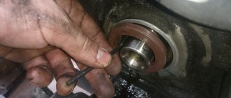
- Using a special puller, the bearing device is removed from the landing site. If you don’t have a tool, you can use a hammer and a mandrel of the appropriate size. The use of a wooden board is allowed.
- The spacer sleeve is removed from the rotor mechanism pulley.
- This unit is removed from the rear cover of the generator device.
- The leads of the stator winding are disconnected from the rectifier. To do this, you need to unscrew the nuts that secure them. After dismantling the fastening elements, the bolts are unscrewed. They record the conclusions themselves.
- Insulating pads are located on the bolts. The stator winding must be removed from the unit housing.
The next step is to remove the diode bridge; this requires the following steps:
- Use a wrench to unscrew the nut that secures contact number 30.
- Next to this pin there is a block with a plug. This element must be dismantled. But you should first release the fastener using a small flat-head screwdriver.
- The latch is disconnected from the inside. Then the block with wires is pushed inside. The plug should remain on the cover. The diode bridge is dismantled from it.
- The next step requires a vice. The rotor mechanism must be clamped into the equipment so that the rear bearing device is located on the top.
- Using a puller, the part is dismantled. To do this, you need to put the tool on top of the assembly and pull the bearing element off the pulley.
Unscrewing the generator impeller
Disconnecting pin 30, connector and dismantling the diode bridge
Removing the bearing device from the pulley
After disassembling the elements of the generating set, replacing the failed components:
- To change bearing parts, you need to check the markings of the elements. Similar spare parts are purchased at the auto store. Even if the bearings are visually intact, it is recommended to replace them. The parts are not interchangeable, so when purchasing, be sure to follow the markings.
- The same goes for the diode bridge. The markings are rewritten from the part, only after that the spare part is purchased. If there is visible damage to this device or metal oxidation has occurred, the unit must be replaced. It is fixed to the generator housing with four nuts. The diode bridge is located at the back, on the inside.
- A visual diagnosis of the front cover of the generating set is carried out. If there are cracks or other damage, the casing must be replaced. When performing visual diagnostics, it is important to pay attention to the fastening elements.
- The diameter of the seat for the bearing parts in the front cover is measured. If the socket for their installation is more than 4.2 cm in diameter, the cover must be replaced.
- Then a visual check is made of the rear of the unit. If there is damage on it in the form of cracks, it must be replaced. Wear or breakage of the seating area under the bearing element is not allowed. If such damage occurs, the cover must be replaced.
- Visual diagnostics of the internal surface of the stator device is carried out. Scratches and other defects resulting from touching the anchor are not allowed. If wear is detected, the bearing elements or the generator set cover are replaced.
The winding of the dismantled rotor mechanism is checked, the task is carried out as follows:
- It is necessary to visually inspect the slip rings. These elements must be replaced if defects are found. We are talking about signs of wear, scuffs, scratches, etc. In principle, the rings do not need to be replaced if the damage is minor. But then they will have to be sanded, for this you will need fine-grained sandpaper.
- If damage to the elements cannot be removed with sandpaper, you can try turning them on a lathe. When using the equipment, it is necessary to remove a minimum layer of metal and then sand the surface.
- Using a tester, the resistance value of the winding of the rotor mechanism is checked. To do this, the device must be connected to slip rings. If the diagnostics show that the resistance tends to infinity, this indicates a break inside the winding. To correct the problem, you will need to replace the rotor mechanism.
- Using a test lamp, a diagnosis is made of the absence of a short circuit in the winding of the anchor device on the housing. To do this, you need to activate the light source by connecting it to the battery. One contact is connected to the body of the anchor device, and the other is connected to each ring in turn. The indicator light should not light up when the rotor is operational. If it is activated, this indicates a short circuit in the winding, then the armature will need to be replaced.
Vyacheslav Lyakhov spoke in detail about performing diagnostics, as well as repairing the unit in the VAZ 2109 car.
Generator assembly
If you managed to disassemble and repair the unit, then after completing the work you will need to put it back together:
- The rear bearing device is installed at the landing site, on the shaft. A wooden board and a hammer are used to complete the task. The bearing is carefully driven in so as not to damage the part. To do this, just hit it several times.
- If the diode bridge was dismantled, it must be reinstalled. The device is located in the back cover of the case.
- The protective casing is then installed on the anchor device so that the bearing element is completely seated. To simplify the action, you can use a hammer. Light blows on the cover clog the bearing; it must be placed on the pulley. The same part installed on the front cover is replaced and fixed using plates.
- Then the generator device is dismantled from the vice. Before installing the front cover on the assembly, the spacer ring is mounted on the pulley. This part should be located between the thrust recess and the front bearing device.
- The cover is installed from the front, the stud nuts are tightened using the crosswise method. This will ensure more uniform tightening of the fastening elements.
- The stud is installed in the recess on the shaft of the anchor device. Then the impeller is installed, the element is clamped with a nut.
- At this point, the assembly procedure for the generator device can be considered complete. All that remains is to install the voltage regulator with brushes at the landing site.
Evgeny Bragin described the assembly procedures for the “nine” unit, indicating all the nuances of this process.
Installation and connection
Installation of the generator unit is carried out in the reverse order; when performing this task, it is important not to forget to connect the wire to the control device:
- A fixation bracket is screwed to the installation. A wrench is used.
- The bracket is then screwed into place with the generator set. When performing this task, you do not need to tighten the nut all the way.
- Self-tapping screws are used to secure the unit's dust protection.
- The drive belt is being installed on the generator set pulley.
- The tensioning element strip is being installed.
- The drive belt is tensioned. When performing this task, it is important that the deflection of the product is about 1-1.5 centimeters. When tightening the belt, it is necessary to tighten the nut on the tensioner bar. Then this element is clamped on the bracket until it stops.
After the installation is completed, you need to connect the terminal blocks to the generator device. When performing the task, you need to make sure that the clamps are disconnected from the battery. There should be a total of three wires connected to the unit. Paired cables are secured with nuts to a stud located on the back cover. A male connector must be installed in a female connector.
Then the terminal clamps are installed on the battery, and the power unit is started. The generator unit supplies the voltage required for full operation of all machine devices.
To be sure that the unit is working properly, you need to use a voltmeter to diagnose the voltage that the unit produces.
Generator set connection diagram
Disassembling the device
For disassembly you will need the following tools:
- set of wrenches;
- bearing puller;
- vice.
With their help, the disassembly process will significantly speed up. When starting work, you need to unscrew the hardware securing the rotor shaft with a 19mm wrench. Usually they are fastened very tightly, so you will have to put in a lot of effort
In the process of unscrewing the fastener elements, it is important to remember their location, so it is recommended to make a rough sketch on paper. This diagram will help you not get confused when assembling the device
Place the generator with its back side up and unscrew the 4 fastening elements using an 8 key. This way you can open the front part of the generator housing. There is a bearing located there, which is secured using plates. Unscrew the hardware securing its plates and release the bearing from its seat.
If it does not give in, it is necessary to help it with a wooden strip, the size of which coincides with the dimensions of the bearing. The undisassembled part of the generator will need to be secured in a vice and the back of the housing will need to be pulled to release the element. All that remains is the rotor shaft and another bearing, which are removed using a puller. To do this, you need to place the tool on the bearing and release it from the shaft seat.
Generator parts: 1 – voltage regulator assembled with brush holder for generators produced since 1996; 2 – voltage regulator and brush holder for generators produced before 1996; 3 – terminal block for additional diodes; 4 – insulating bushings; 5 – rectifier block; 6 – contact bolt; 7 – stator; 8 – rotor; 9 – spacer sleeve; 10 – inner bearing mounting washer; 11 – drive side cover; 12 – pulley; 13 – outer bearing mounting washer; 14 – coupling bolt; 15 – front rotor ball bearing; 16 – bushing; 17 – cover from the side of the slip rings; 18 – buffer sleeve; 19 – clamping sleeve; 20 – capacitor
Having dealt with the bearings, you will need to check the diode bridge, which is located inside the back of the device housing. If mechanical damage or oxidation is detected on the surface of the part, you need to dismantle the bridge by unscrewing the 4 fastening elements and replace it with a new one. The cost of all the above-mentioned parts does not exceed 800-1000 rubles. in total, so you can replace everything at once if possible.
The VAZ 2108 device, like any other vehicle, involves powering electrical circuits from a battery. To ensure that the battery is always in good condition and does not let you down at the most inopportune moment, a generator is always connected to it. The battery is especially important when the engine is ignited; while driving, when the car develops sufficient speed, the entire electrical circuit is powered by the generator.
When the question arises about connecting additional powerful electrical appliances to the car, it is very important to match their load with the permissible power of the generator. To do this, it is important to know its technical characteristics
And if the battery lack of charge indicator suddenly lights up, it’s better not to even look under the hood without understanding how the electrical charging circuit, voltage regulator and ignition work.
Safety precautions when working
Nuances that must be taken into account when repairing a VAZ 2109 generator:
- All control and adjustment work related to diagnosing the unit with the engine running must be carried out in a ventilated area or outdoors. If it is a garage, it is recommended to open the doors or provide good ventilation.
- Before carrying out the task, you need to button up your sleeves if the work is performed in a shirt. All hanging ends of clothing should be removed to prevent them from getting caught on the operating pulley.
- To carry out repairs, a specialized tool is used.
- The generator must not be allowed to fall after it has been removed during transportation to the machine. This can lead to complete failure of the unit.
- Repairs should only be carried out using serviceable, clean and oil-free tools.
- If the nuts are rusty and difficult to unscrew, it is recommended to treat the elements with kerosene or WD-40 before turning them out. Dismantling is carried out with preliminary tapping with light blows of a hammer.
- The vehicle is inspected using a 36-volt light bulb. If the diagnosis is performed in a ditch, a 12 V light source will be required. It is important that the light bulb is equipped with a safety net.
Basic faults
- First, remove the generator. You can do without removing it, but this is only if you are 100% sure that the problem is in the brushes, and also that the other parts of the generator are absolutely in good working order.
- Then you need to disassemble the generator to get to the brushes. You can learn how to do this from previous articles, links to which are given above.
- Blow out the brush holder seat with compressed air, then wipe with a clean cloth.
- We solder the generator brushes; for this you will need a soldering iron. Note! You can also replace the generator brushes in another way - together with the brush holder. In this case, you will have to buy a new brush holder with new brushes; this option is much simpler, but also more expensive.
- We also recommend cleaning the contacts and checking the elasticity of the springs.
- Polish the slip ring (optional).
After replacement, you may receive errors about a faulty battery or generator; you do not need to immediately try to find the cause of the failure. This phenomenon is not uncommon, because new brushes are just starting to get used to it. After some time, everything will return to normal and you can safely continue to operate the car.
REPLACING THE GENERATOR VOLTAGE REGULATOR RELAY. GENERATOR BRUSHES. Replacing generator brushes. VAZ 2110.
Repair costs
The approximate cost of spare parts is shown in the table.
| Name | Price, rub |
| Price of a set of bearing elements | Around 150 rubles. |
| Generator diode bridge | 200 rub. |
| Charging relay | About 150-200 rub. |
| Removal tool for bearing elements | Around 100-200 rubles. |
| Prices are relevant for three regions: Moscow, Chelyabinsk, Krasnodar. | |
Loading …
VAZ 2108 generator circuit
It’s worth talking about the latter separately. The middle part, the generator stator, consists of a series of thin metal plates pressed tightly together. They are often boiled on the outside to prevent separation.
- Alternator. The 37.3701 or 94.3701 series can be installed.
- Negative diode.
- Additional diode.
- Positive diode.
- Alternator warning lamp, also known as battery discharge lamp.
- Instrument cluster.
- Voltmeter.
- Relay and fuse box located in the engine compartment in the compartment between the engine and the vehicle interior.
- Additional resistors built into the fuse mounting block.
- Ignition relay.
- Egnition lock.
- Accumulator battery.
- Capacitor.
- Rotor winding.
- The voltage relay is located in the engine compartment.
Poor battery indicators
When the battery is constantly discharged, this is indicated by indicators on the instrument panel.
- Illuminated warning lamp on the instrument panel.
- Low voltage reading on standard voltmeter.
- Dim light from lighting fixtures.
- Weak rotation of the crankshaft when starting the starter.
The most obvious indicator is a light on the instrument panel with a battery icon. Pay attention to it by turning the key once in the ignition switch. It should light up brightly along with other icons. Lights up, but dimmer than others? The first bell is that there is no charging. Start the engine. When the battery is charged, the icon should go out.
If the lamp is still dimly lit when the engine is running, the battery is definitely not receiving the required charge. If you have a voltmeter on your dashboard, it should read between 13.5 and 14 V. If the number on the screen is lower, the alternator is not fully charging the battery.
A WEAK CHARGE IS FELT EVEN WHEN THE STARTER IS STARTED. THE CRANKSHAFT ROTATES WITH INSUFFICIENT FORCE AND IS NOT ABLE TO TRANSFER NORMAL TORQUE. ALSO INDICATED BY THE DIME LIGHT OF THE VAZ 2109 LIGHTING DEVICES IS THE BATTERY CHARGE IS LOW.
Electric generator diagnostics
Let's start by identifying the causes of the breakdown:
- Noisy operation of the electric generator means wear on the generator bearings
- If the voltage at the “output” is low, most likely the brushes are worn out or the tension of the drive belt has simply weakened
- An increase or decrease in the electrical voltage at the “output” may indicate a malfunction of the diode bridge
We carry out initial diagnostics of faults:
- We check the voltage at the battery contacts with a voltmeter. If the generator is working properly, then with the engine running, the voltage at the terminals should be 13.8 - 14.5 volts
- We place our palm against the body of the unit and detect vibration. If the shaft bearings are worn out, vibration on the housing will be noticeable; it is almost impossible to confuse it with another malfunction
- Check the belt tension: with the engine turned off, press the belt with your finger, the deflection does not exceed 1 - 1.5 centimeters (if more, then it is necessary to increase the belt tension)
We check the diode bridge using a 12-volt test lamp and a battery:
Note: The rectifier unit (aka diode bridge) is checked without removing the electric generator from the machine. To do this, disconnect the wires from the battery, then the generator, and remove the block from the voltage regulator.
- To check the positive diodes, we connect a test light to the “+” (plus) of the battery, and the second contact of the lamp to terminal “30” of the electric generator, and the wires coming from the “-” (minus) of the battery to any bolt of the diode bridge. If the light is on, this means a short circuit in the positive diodes - the unit needs to be replaced
- To check the negative diodes, we connect a test light to the “+” battery and the second contact of the lamp to any bolt of the diode bridge, and connect the wires coming from the “-” battery to the unit body. If the light comes on, this means a short circuit in the negative diodes - the unit must be replaced