Working brake system VAZ-2101
Working brake system VAZ-2101
Repair and operation manual - Brake system VAZ-2101 - VAZ-2107 - Service brake system VAZ-2101
Service brake system VAZ-2101
Brake system diagram
1 – front brake protective housing; 2, 18 – pipelines connecting two cylinders of the front brake caliper; 3 – caliper; 4 – hydraulic drive reservoir; 5 – brake light switch; 6 – parking brake lever; 7 – adjusting eccentrics of the right rear brake; 8 – fitting for bleeding the hydraulic drive of the rear brakes; 9 – pressure regulator; 10 – stop signal; 11 – rear brake wheel cylinder; 12 – lever for manual drive of the pads and expansion bar; 13 – adjusting eccentric of the left rear brake; 14 – brake pad; 15 – rear cable guide; 16 – guide roller; 17 – brake pedal; 19 – fitting for bleeding the hydraulic drive of the front brakes; 20 – brake disc; 21 – main cylinder.
This brake system has two circuits that provide independent drive to the front and rear wheel brakes. Both circuits are driven by one pedal 17 (see Fig. Diagram of the brake system), which is attached together with the clutch pedal to the front panel of the body using a bracket.
In addition to the brake pedal, the hydraulic drive includes the main brake cylinder 21, the main cylinder reservoir 4, the rear brake pressure regulator 9, the brake mechanisms of the front and rear wheels along with the working cylinders and pipelines.
Master brake cylinder
The brake master cylinder is attached to the clutch and brake pedal bracket. Pistons 3 and 5 (see Fig. Main cylinder of the hydraulic brake drive) drive different circuits. Both pistons take their original position under the action of springs 8, which press the pistons until they stop against the screws 7. The tightness of the pistons in the cylinder is ensured by four o-rings 6. The housing is closed at the front with a plug 1.
Pedal assembly
Pedals 6 (see Fig. Parts of the clutch and brake pedal bracket) and 19 are suspended on bracket 1 using an axis made in the form of a bolt.
Axle 18 is secured with nut 2 in the holes of the bracket cheeks. The internal bushings 4 and 14 of the clutch and brake pedals are clamped on the axis between the cheeks of the bracket and the spacer bushing 7. Pedals are pivotally mounted on these bushings, in the hubs of which outer bushings 5 and 9 are pressed. Pushers 20 are pivotally attached to both pedals, acting on the pistons of the hydraulic cylinders. The reverse travel of the clutch pedal is limited by a buffer 11 installed on the head of the bolt 12. The master cylinders of the clutch release drive and the brake drive are attached to the bracket shelf.
Pressure regulator
A pressure regulator 9 (see Fig. Brake system diagram) is connected to the rear brake drive circuit, which adjusts the pressure in the rear brake drive depending on the position of the body relative to the rear axle beam, i.e. depending on the vehicle load. It acts as a restriction valve that automatically cuts off the flow of brake fluid to the rear brakes, reducing the likelihood of rear wheel skidding when braking.
The regulator is mounted on the body bracket and connected to the rear axle beam through torsion lever 12 (see Fig. Parts of the pressure regulator drive) and rod 7. The other end of the torsion lever acts on piston 10 (see Fig. Rear brake pressure regulator in non-working position) .
Fluid enters cavity A from the master cylinder, and from cavity B enters the wheel cylinders of the rear brake drive.
The force P acting on the piston from the torsion lever increases as the body approaches the axle beam and decreases as the body moves away from the rear axle beam.
Before the pressure regulator begins to operate, piston 10 rests against plug 6 under the action of force P and spring 9. In this case, gaps are formed through which cavities A and B communicate, i.e. the pressure in them will be the same and equal to the pressure in the hydraulic brakes.
When the brakes are applied, the rear part of the car rises by inertia and, therefore, the pressure on the piston from the side of lever 1 decreases. The force of fluid pressure on the upper end of the piston with a larger surface area at some moment exceeds the force of fluid pressure acting on the piston from below, and the piston will go down until it stops at seal 7. In this case, cavities A and B will separate, and different pressures will be created in them: in cavity A, pressure Pa will be equal to the pressure in the main cylinder, and in cavity B, pressure Pb will be less by an amount that determines equilibrium of the piston, which is under the influence of pressure Pa and Pv, spring 9 and the force of the torsion lever. Thus, by partial or complete separation of cavities A and B by piston 10, the braking torque on the rear wheels is regulated.
Front wheel brake
The front wheel brake mechanism is disc. It consists of those shown in Fig. Front wheel brake mechanism (Parts of the front wheel brake caliper) caliper 12 (4) assembled with working cylinders 17, brake disc 18, two brake pads 16 (11), connecting pins 8 (8) and pipelines.
The caliper is attached to the bracket 11 with two bolts 9, which are locked by bending the locking plates onto the edge of the bolts. Bracket 11, in turn, is attached to the flange of the steering knuckle 10 along with the protective casing 13 and the steering arm. The caliper has a radial groove through which a brake disc 18 and two transverse grooves pass for placing brake pads 16. In the caliper bosses there are two windows with guide grooves in which two opposing cylinders 17 are installed. To fix the cylinders relative to the caliper, a spring retainer is installed in the cylinder 4, included in the side groove of the caliper.
Each cylinder contains a piston 3 (1), which is sealed with an elastic rubber ring 6 (3). It is located in the cylinder groove and tightly compresses the piston surface. The cylinder cavity is protected from contamination by a rubber cap 7 (2).
The working cavities of the cylinders are connected to each other by pipeline 2 (5). Fitting 1 (6) is screwed into the outer cylinder for bleeding the front brake drive circuit, and the hose fitting for supplying brake fluid is screwed into the inner cylinder.
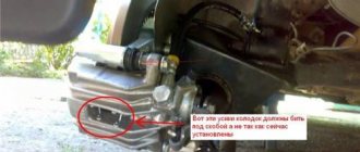
Piston 3 rests against brake pads 16, onto which linings 5 are glued. The pads are installed on pins 8 and are pressed against them by springs 15 (7). Fingers 8 are held in the cylinder by cotter pins 14 (9).
Brake disc 18 is attached to the wheel hub with two locating pins.
Rear wheel brake
The rear wheel brake is drum type, with self-aligning pads. Brake pads 3 with linings 7 (see Fig. Brake mechanism of the rear wheel), wheel cylinder 1 and other parts are mounted on the brake shield, which is attached to the flange of the rear axle beam. A package of plates is attached to the bottom of the shield with two rivets, one of which is a support for the lower ends of the brake pads. To regulate the gap between the shoes and the drum, eccentrics 8 are used, on which the shoes rest under the action of tension springs 5 and 10.
In the housing 4 (see Fig. Parts of the wheel cylinder) of the wheel cylinder, there are two pistons 2, which are expanded by a spring 7 with support cups 5. The same spring presses the seals 3 to the end of the pistons.
Stops are pressed into the pistons, into the grooves of which the upper ends of the brake pads rest. The outlet of the pistons from the cylinders is sealed with rubber caps 1. To bleed the rear brake drive, a fitting 6 is screwed into the cylinder.
Quote