The brake system of a car requires timely monitoring to identify possible faults and must be checked every six months.
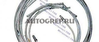
| Standard brake pipe repair kit for VAZ 2110. |
It is best to time it to coincide with the end of the winter period, as it is the most difficult to operate. In winter, the road surface is treated with chemicals that have an aggressive effect on all elements of the body, including the brake system.
When checking the brake system, you need to check the condition of the brake fluid pipelines, brake hoses, their fastening, as well as the condition of the brake pads. At the same time, cracks, abrasions of the outer coating, swelling, leakage of brake fluid and other damage are not allowed on the brake pipes.
It is advisable to carry out the test using a powerful lamp and a mirror so that any malfunction can be identified. Timely replacement of worn-out brake system components will guarantee your safety.
If damage to the brake hoses or pipelines is revealed during the inspection, then a mandatory replacement of the VAZ 2110 brake pipes and hoses will be required.
Most often, you have to change brake hoses after a certain mileage, namely in the region of 70-100 thousand kilometers, or when a malfunction is detected. Brake pipes last quite a long time and replacement of VAZ 2110 brake pipes occurs when they are corroded or mechanically damaged.
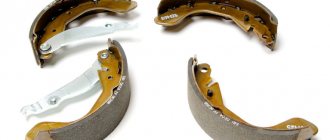
To replace, you need to purchase a set of VAZ 2110 brake pipes. In this case, you can purchase either brake pipes already bent to the desired configuration, or simply straight ones, which will need to be given the profile of the removed brake pipes.
| Video of replacing brake pipes on front-wheel drive VAZ cars. After watching this video, we can say that replacing brake pipes on a VAZ 2110 at home is not particularly difficult. |
It is better to purchase ready-made (factory bent) tubes, which will significantly simplify the process of replacing them.
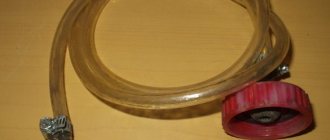
If you purchase straight brake pipes, you will need a tool to bend them (you can use a spring with a suitable internal diameter where the pipe should fit when bent). Steel double-layer brake pipes are more reliable.
It will be more economical to purchase an unmolded copper line, but you will need to bend it yourself, observing all the necessary dimensions, which will require more time to replace.
To work, you will need an inspection hole or overpass. Carrying out the replacement simply on a level surface with the help of a jack is also possible, but it is quite labor-intensive and dangerous in terms of work safety.
To replace faulty brake hoses or tubes, you will need a special wrench for working with the VAZ 2110 brake system, as an addition and a gas wrench (first number) for disconnecting the fittings on the master brake cylinder, working cylinders, as well as in the brake hose connections.
It is also necessary to have a set of wrenches for: 10, 13/14, 17 mm, composition VD 40 or similar and new brake fluid.
The procedure for replacing brake pipes on a VAZ 2110
- Before starting the replacement, you need to disconnect the terminal from the battery for safe work;
- Replacement of brake pipes must be done starting from the main brake cylinder in turn to each wheel cylinder;
- The wheel bolts are loosened and the car is jacked up to a convenient height for work;
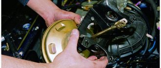
- The brake pipe fittings are removed one by one from the brake master cylinder and the holes are closed with plugs;
- The pipeline is carefully released from plastic and metal fasteners towards a specific wheel. The protective plastic box must be removed;
- The brake hose fitting on the wheel is unscrewed, where the tube is replaced and the damaged line is removed;
- The new brake pipe is installed in the opposite direction, “going” from the wheel to the brake master cylinder;
- All tube holders are put back into place; those damaged during dismantling are replaced with new ones;
- The new pipeline is blown through with compressed air and connected.
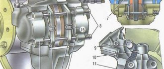
Wheel cylinder
1 – block stop; 2 – protective cap; 3 – cylinder body; 4 – piston; 5 – seal; 6 – support plate; 7 – spring; 8 – crackers; 9 – thrust ring; 10 – thrust screw; 11 – fitting; A – slot on the thrust ring
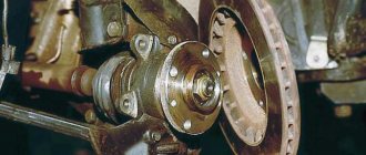
The rear wheel brake mechanism (Fig. Rear wheel brake mechanism) is drum-type, with automatic adjustment of the gap between the shoes and the drum. The automatic clearance adjustment device is located in the wheel cylinder. Its main element is a split thrust ring 9 (Fig. Wheel cylinder), installed on the piston 4 between the shoulder of the thrust screw 10 and two nuts 8 with a gap of 1.25–1.65 mm.
When is it necessary to replace pipes and other elements of the brake system?
Brake pipes are changed quite rarely. The need for this arises only if the machine has been in use for a long time, in unfavorable conditions conducive to the development of corrosion, or in the event of any mechanical damage.
You can assess the condition of these components yourself by looking under the car body, or by bringing your “iron horse” for inspection by technicians from the service center. According to the regulations, diagnostics of all components of the brake system must be carried out at least once a year, preferably at the end of the winter period. You can combine the inspection with the next oil change.
Rubber hoses on all wheel cylinders must be replaced, regardless of their condition, every 70-100 thousand km. mileage Pipelines are replaced only as needed.
To carry out the work you will need the following tools:
- Jack;
- Phillips screwdrivers;
- Set of wrenches for: “10”, “14”, “17”;
- Clamping key to “10”;
- Clamping pliers;
- Balloon wrench;
- Anti-corrosion composition;
- Brake fluid (to replenish the system).
What to consider?
The design of the brake system and the principle of its operation are almost identical for all car models. Accordingly, the method of its restoration is also the same for all brands of vehicles.
All pipeline repair work can be carried out in a repair pit, overpass or on a flat area by lifting the machine with a jack.
A set of tubes can be purchased at any auto store. You can order a pipeline of a given length, already bent as required, specifically for a specific car model. Or you can buy a universal copper line, and then give it the required shape and length yourself. The latter option is more economical, however, and there is much more fuss.
The main stages of replacing brake pipes on a VAZ 2109, 2110
You can replace the pipeline lines in the direction from the main brake cylinder to each wheel according to the following diagram.
- Disconnect the battery terminals.
- Raise the car to the desired height using a jack.
- Remove the car wheels.
- Using a “10” wrench, unscrew the nut securing the tube to the master cylinder and install a plug for dust and dirt in the supply hole.
- Carefully release the pipeline towards the wheels. Remove the protective plastic box and remove the line from the metal and plastic holders. Try to do this carefully so as not to damage the clips.
- Unscrew the brake hose fitting and remove the damaged line.
- Start installing the new tube in the opposite direction: from the wheel to the master cylinder.
- Reinstall all holders, replacing worn or damaged parts as necessary.
- Blow out the pipeline with compressed air, connect it to the system and bleed the brake system according to the instructions, replenishing the missing fluid as necessary.
Symptoms of a problem
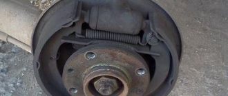
Understanding that it’s time to repair drum mechanisms is quite simple:
- Smudges appeared under the rear wheels where the VAZ 2110 was parked. The rod or hoses were damaged.
- The wheels brake unevenly - this defect can be felt at high speed.
- Knock in the rear wheels and malfunction of the drum mechanisms - such a defect appears when a foreign body gets into the device. This happens extremely rarely.
- You can determine that the tubes or cylinder need to be replaced even by appearance. This is indicated by cracks, abrasions on the outer part of the hoses, deformation of the cylinder and its rod, and rupture of tubes.
- Sometimes the malfunction of the drum mechanism can be caused by peeling of the inner part of the tubes. Such a defect cannot be identified visually, but if you disconnect these elements of the VAZ 2110 and look inside, you can see the blockage.
Features of replacing brake hoses
When replacing brake pipes on a VAZ 2110, it is a good idea to check the condition of the elastic hoses. If you notice even minor cracks and mechanical damage on them, replace them. Also install new hoses if the service life of the old ones has already exceeded the required limit.
The elastic hose replacement scheme consists of the following steps:
- Clean the cylinder well with a wire brush, treating it with rust remover if necessary;
- Using a “14” wrench, unscrew the wheel caliper fitting;
- Plug the caliper hole to prevent dirt from getting into it;
- Using wrenches “17” and “10”, unscrew the fitting and disconnect the hose from the tube;
- Remove the elastic hose holder;
- Install the new hose in sequence from tube to caliper.
Replacing the brake system elements described above is not a very pleasant matter. However, if you are going to replace the piping and hoses, be glad that you won't have to do it anytime soon.
The brake system appeared on the first cars. Its presence has become the key to the safety of the driver and passengers. The first brake system did not have a complex mechanism of action and consisted of several mechanical parts that created the necessary friction on the wheel drive for its subsequent stopping.
The second stage in the development of the braking system was the application of the laws of hydraulics. With this method of braking, the interaction between the brake pedal and the working parts of the brake system is carried out using a special fluid called “brake fluid” (or abbreviated as TF). Brake fluid allows you to stop your vehicle more efficiently. In addition, the use of brake fluid softened the pressure on the brake pedal and made driving more comfortable.
For successful circulation of brake fluid from the brake drive system to the working parts, it is carried out through special pipes. Initially, they were made in the form of hoses, but since they were unreliable, they were replaced by another material.
Pressure regulator
1 – pressure regulator housing; 2 – piston; 3 – protective cap; 4, 8 – retaining rings; 5 – piston sleeve; 6 – piston spring; 7 – body bushing; 9, 22 – support washers; 10 – sealing rings of the pusher; 11 – support plate; 12 – pusher bushing spring; 13 – valve seat sealing ring; 14 – valve seat; 15 – sealing gasket; 16 – plug; 17 – valve spring; 18 – valve; 19 – pusher bushing; 20 – pusher; 21 – piston head seal; 23 – piston rod seal; 24 – plug; A, D – chambers connected to the main cylinder; B, C – chambers connected to the wheel cylinders of the rear brakes; K, M, N – gaps
The pressure regulator regulates the pressure in the hydraulic drive of the rear wheel brakes depending on the load on the rear axle of the vehicle. It is included in both circuits of the brake system and through it brake fluid flows to both rear brake mechanisms.
Pressure regulator 1 (Fig. Pressure regulator drive) is attached to bracket 9 with two bolts 2 and 16. At the same time, front bolt 2 simultaneously secures fork bracket 3 of lever 5 of the pressure regulator drive. A double-arm lever 5 is hinged on the pin of this bracket with a pin 4. Its upper arm is connected to an elastic lever 10, the other end of which is pivotally connected to the rear suspension arm bracket through an earring 11.
Bracket 3 together with lever 5 can be moved relative to the pressure regulator due to the oval holes for the fastening bolt. This regulates the force with which lever 5 acts on the regulator piston (see subsection 6.4.2). The regulator has four chambers: A and D (Fig. Pressure regulator) are connected to the main cylinder, B to the left, and C to the right wheel cylinders of the rear brakes.
In the initial position of the brake pedal, piston 2 (see Fig. Pressure regulator) is pressed by lever 5 (see Fig. Pressure regulator drive) through leaf spring 7 to pusher 20 (see Fig. Pressure regulator), which is pressed against the saddle under this force 14 of valve 18. In this case, valve 18 is pressed away from the seat and a gap H is formed, as well as a gap K between the piston head and seal 21. Through these gaps, chambers A and D communicate with chambers B and C.
When you press the brake pedal, fluid flows through gaps K and H and chambers B and C into the wheel cylinders of the brake mechanisms. As the fluid pressure increases, the force on the piston increases, tending to push it out of the housing. When the force from the liquid pressure exceeds the force from the elastic lever, the piston begins to move out of the body, and after it, under the action of springs 12 and 17, the pusher 20 moves together with the sleeve 19 and rings 10. In this case, the gap M increases, and the gaps H and K decrease . When the gap H is completely selected and the valve 18 isolates chamber D from chamber C, the pusher 20, together with the parts located on it, stops moving after the piston. Now the pressure in chamber C will vary depending on the pressure in chamber B. With a further increase in the force on the brake pedal, the pressure in chambers D, B and A increases, piston 2 continues to move out of the body, and sleeve 19 together with o-rings 10 and plate 11 under increasing pressure in chamber B, it shifts towards plug 16. At the same time, the gap M begins to decrease. Due to the decrease in the volume of chamber C, the pressure in it, and therefore in the brake drive, increases and will be practically equal to the pressure in chamber B. When the gap K becomes zero, the pressure in chamber B, and therefore in chamber C, will increase less degree than the pressure in chamber A due to throttling of the liquid between the piston head and seal 21. The relationship between the pressure in chambers B and A is determined by the ratio of the difference in the areas of the head and piston rod to the area of the head.
Design and principle of operation of brake pipes
The car is braked by pressing the brake pedal. The pedal lever acts on a vacuum or any other booster, which creates the necessary pressure on the brake fluid. The liquid compresses and goes into a zone where this pressure is minimal. It enters the brake pipes, through which it is directed to the working parts of the brake system. The fluid puts pressure on the brake pads, causing them to compress. When you release pressure on the brake pedal, the pressure in the booster decreases, and the spring drive of the brake pads unclenches them and sends the fluid back to the booster (the area of least pressure).
The passage of liquid is carried out through tubes made of metal. The tubes extend from the vacuum booster and are laid under the car to the working parts of the brake system. The joints of the tubes are made in the form of threaded connections, which makes it possible to achieve maximum reliability when creating high pressure in the system.
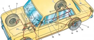
To increase the reliability of the braking system, the pipes are connected diagonally, which allows the brakes to be used if one of the lines fails. So, for example, from the vacuum booster, one tube connects the working part of the brakes of the front left and rear right wheels, and the second tube directs the brake fluid to the front right and rear left wheels. At the junction of all four pipes, a special pressure regulator is installed, which filters out excess pressure from the system so that it does not cause a breakthrough in the lines.
Pressure regulator drive
1 – pressure regulator; 2, 16 – pressure regulator mounting bolts; 3 – bracket for the pressure regulator drive lever; 4 – pin; 5 – pressure regulator drive lever; 6 – axis of the pressure regulator drive lever; 7 – lever spring; 8 – body bracket; 9 – pressure regulator mounting bracket; 10 – elastic lever of the pressure regulator drive; 11 – earring; 12 – earring bracket; 13 – washer; 14 – retaining ring; 15 – bracket pin; A, B, C – holes
How to repair brake pipes
This process requires the car enthusiast to have extensive locksmith skills and the ability to use special tools. Repairs are carried out in cases where it is not possible to replace the damaged line; it involves saving money on the purchase of a new pipe system and extends the service life of the old one.
To carry out repairs you must:
1. Unscrew the damaged tube from the cylinder or brake caliper.
2. After disconnecting, it is necessary to cut off the damaged area using a pipe cutter.
3. Clamp the tube 50 millimeters from the edge of the cut and chamfer the edge of the tube using a drill.
4. Remove all that remains of the chips and insert a fitting intended for connecting the tube to the brake operating mechanism into the cut area.
5. Insert the end of the tube into the special equipment and flare it. The main line that has undergone repairs must be purged with compressed air. And only after this is it installed with a working mechanism or another pipeline system using an adapter.
As for the length of the tube, this parameter depends on the car model. On some cars, the brake pipes have a reserve that allows you to shorten the pipe and reconnect it to the working mechanism. The metal from which the brake tube is made is flexible, so there should not be any difficulties with its position.
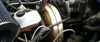
Master cylinder with reservoir
1 – main cylinder body; 2 – low pressure sealing ring; 3 – drive piston of the “left front–right rear brake” circuit; 4 – spacer ring; 5 – high pressure sealing ring; 6 – pressure spring of the sealing ring; 7 – spring plate; 8 – piston return spring; 9 – washer; 10 – locking screw; 11 – drive piston of the “right front–left rear brake” circuit; 12 – connecting sleeve; 13 – tank; 14 – brake fluid emergency level sensor; A – gap
Master cylinder with sequential pistons. A tank 13 is mounted on the master cylinder body, in the filler neck of which a sensor 14 for emergency brake fluid level is installed. The high pressure O-rings 5 and the rear wheel cylinder rings are interchangeable.