What are the VAZ 2110 fuse box relays responsible for?
K1 – relay for monitoring the health of light bulbs; K2 – front wiper relay; K3 – repeater and alarm relay; K4 – low beam relay; K5 – high beam relay; K6 – additional relay; K7 – relay for turning on the heated rear window; K8 – backup relay (not installed on 110 series vehicles);
F1-F20 in the diagram are fuses. The circuits in the car are protected by fuses based on a certain rated current (in A). The battery charging circuit, generator circuit, ignition and engine starting are exceptions.
To replace a faulty fuse, first find the one that has blown, then eliminate the reason why it was damaged and then install a new one. Below is a list of fuses and information on each one.
* Never replace fuses with jumpers, this can lead to failure of various components and elements, including failure of the wiring tracks in the fuse box and even a car fire.
Reasons for premature failure of fuses
- A natural factor is the duration of operation without intermediate prevention;
- Ingress of moisture, formation of condensation, oxidation of terminals, drying out of the insulating layer, open circuit of the electrical supply;
- Mechanical damage, accident, impact, collision;
- Damage to the car fender, windshield, which contributed to damage to the mounting block;
- Short circuit in the electrical supply circuit;
- Exposure to ultraviolet rays.
If after replacing the modules the equipment does not work, then the power supply circuit line is most likely damaged. In the worst case scenario, part failure. Carefully inspect the wiring sections from the battery, generator, starter to the relay switch.
The operating instructions for the technical means indicate the interval before replacing the modules of the mounting block is 40,000 km. In practice, the resource is 5 – 7 thousand km longer.
To prevent premature wear of modules, systematically check the condition of the wiring insulation, the quality of fixation of the terminals, and remove oxidation with fine sandpaper.
As consumables, purchase original domestically produced parts. Check the catalog numbers with the data specified in the instruction manual. Imported analogues are comparable in quality to the Russian manufacturer, but the price is twice as expensive
What are the fuses on the VAZ-2110 responsible for?
Decoding fuses.
License plate lamps. Instrument lighting lamps. Side light indicator lamp. Trunk light. Left side marker lamps
Left headlight (low beam)
Left headlight (high beam)
Right fog lamp
Door window motors
Portable lamp (socket)
Engine cooling fan electric motor. Sound signal
Rear window heating element. Relay (contacts) for turning on the heated rear window
Recirculation valve*. Windshield and headlight cleaners and washers ( wiper fuse ). Relay (coil) for turning on the rear window heating
Starboard side marker lamps
Right headlight (low beam)
Right headlight (high beam). High beam warning lamp
Left fog lamp
Electrically heated seats. Trunk lock lock
Relay-breaker for direction indicators and hazard warning lights (in hazard warning mode). Hazard warning lamp
Interior lighting lamp. Individual backlight lamp. Ignition switch illumination lamp. Brake light bulbs. Clock (or trip computer)
Glove box lighting lamp. Heater controller ( heater fuse ). Cigarette lighter fuse for VAZ 2110, VAZ 2111, VAZ 2112.
Locking door locks. Relay for monitoring the health of brake light lamps and side lights. Direction indicators with warning lamps. Reversing lamps. Generator excitation winding. On-board control system display unit*. Instrument cluster. Clock (or trip computer)
Rear fog lamps
Main settings
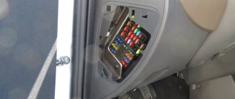
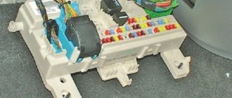
The fuse box is located under the decorative panel to the left of the steering column. Removing it is quite simple: press the latch and lower the structure down. Once you have access to the fuses, they can be removed and checked for integrity using a millimeter. The block contains only 20 fuses, designed for different current strengths. Just look at the color of the fuse to determine what amperage it is designed for:
- tan runs at 5 amps;
- darker brown – at 7.5;
- red – at current strength 10;
- saturated blue – at 15;
- bright yellow is for 20;
- colorless or transparent – by 25;
- green – by 30.
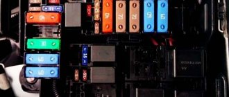
Circuits protected by additional fuses (all fuses are 15 A) on the VAZ-2110:
Additional fuses: 1 – ignition module, controller; 2 – canister purge valve, vehicle speed sensor, oxygen (heating) sensor, air flow sensor; 3 – fuel pump relay, fuel pump, injectors.
Additional relays: 4 – electric fan relay; 5 – electric fuel pump relay; 6 – main relay (ignition relay).
There is a fog lamp fuse installed in the niche of the instrument panel behind the mounting block:
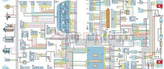
Electrical system diagram of VAZ 21124 in the engine compartment
- electric fan (No. 3);
- electric fan switch relay (No. 22);
- coolant temperature sensor (No. 7);
- electric fuel pump with fuel level sensor (No. 30);
- fuel pump activation relay (No. 21);
- electric heater of the fuel system inlet pipe (No. 4);
- power relay and heater protection fuse (No. 23 and 24);
- air temperature sensor and absolute pressure sensor (No. 5 and 6);
- engine control controller (No. 13);
- SUD fuse box (No. 20);
- fuse box (No. 27);
- ignition relay 21124 (No. 26);
- spark plugs (No. 28);
- car starter relay (No. 25);
- battery (No. 18).
Lada 2111 Agneska › Logbook › relays and fuses
The main fuses and relays on the VAZ-2110, 21102, 21103, 2112 are located on the left side of the steering wheel, just below. The figure shows the designations on the fuse mounting block/
Fuse number Current strength, A Circuits protected by fuse F1 5 Lamps for license plate lights. Instrument lighting lamps. Side light indicator lamp. Trunk light. Left side side light lamps F2 7.5 Left headlight (low beam) F3 10 Left headlight (high beam) F4 10 Right fog lamp F5 30 Door window electric motors F6 15 Portable lamp F7 20 Engine cooling fan electric motor. Sound signal F8 20 Rear window heating element. Relay (contacts) for turning on the heated rear window F9 20 Recirculation valve. Windshield and headlight cleaners and washers. Relay (winding) for turning on the heated rear window F10 20 Reserve F11 5 Side light bulbs on the right side F12 7.5 Right headlight (low beam) F13 10 Right headlight (high beam). Indicator lamp for turning on the high beam. F14 10 Left fog lamp F15 20 Electric seat heating. Trunk lock lock F16 10 Relay-interrupter for direction indicators and hazard warning lights (in hazard warning mode). Hazard warning lamp F17 7.5 Interior lighting lamp. Individual backlight lamp. Ignition switch illumination lamp. Brake light bulbs. Clock (or trip computer) F18 25 Glove box lighting lamp. Heater controller. Cigarette lighter F19 10 Door locking. Relay for monitoring the health of brake light lamps and side lights. Direction indicators with warning lamps. Reversing lamps. Generator excitation winding. On-board control system display unit. Instrument cluster. Clock (or trip computer) F20 7.5 Rear fog lamps
Signs of faulty fuses
- The module has changed color, black dots and carbon deposits are visible on the surface;
- On the instrument panel (European panel) an indicator indicates a malfunction in the engine compartment;
- When the engine is running, the ignition is on, the battery is charged, some mechanisms do not work and do not work correctly;
- In the interior of the car you can hear the smell of burning, melted in the area where the mounting block is located;
- The modules feel hot to the touch.
VAZ 2112 fuse box
If some devices on your VAZ 2112 car have stopped working, fuses or relays may be to blame. At the very least, the first thing you need to do is check them, and then draw some conclusions regarding the malfunctions. Correct diagnosis of many electrical problems will allow you to accurately determine the cause of the inoperability of a particular unit. To find out what fuses and relays do and how to find the right one, read this article.
Scheme
K1 – relay for monitoring the health of light bulbs; K2 – front wiper relay; K3 – repeater and alarm relay; K4 – low beam relay; K5 – high beam relay; K6 – additional relay; K7 – relay for turning on the heated rear window; K8 – backup relay (not installed on 110 series vehicles);
F1-F20 in the diagram are fuses. The circuits in the car are protected by fuses based on a certain rated current (in A). The battery charging circuit, generator circuit, ignition and engine starting are exceptions.
To replace a faulty fuse, first find the one that has blown, then eliminate the reason why it was damaged and then install a new one. Below is a list of fuses and information on each one.
Device, types and principle of operation
A fuse is an electrical switching device that is intended to disconnect a protected electrical circuit by opening it or destroying (burning, melting) specially designed current-carrying elements during the passage of high voltage current through them. Its main elements are the body, the fusible metal insert and the contact part.
The principle of operation is quite simple: if high voltage is supplied to the network, the insert, which is usually made of porcelain or fiber materials, melts. The insert is a mandatory element of all fuses; inside it there is an arc extinguishing device. All devices that are used to protect electrical installations can be divided into four classes:
- With a fuse-link, that is, with a conductive element. When some kind of network failure occurs and the voltage reaches its maximum, this element begins to melt from overheating. This is how voltage is removed from the circuit of an electrical device. Conductive parts are made primarily of metal, most often copper, lead and iron. The operating principle here is that a working balance is created when excess heat is removed.
- Mechanical devices. They are inserted into a cable on which a short circuit occurs. But thanks to this device, the cable is disconnected, and dangerous voltage is no longer supplied to the electrical installation. Protective devices of this type have a sensor that monitors the current strength.
- Electronic fuses. They have built-in transistors that are responsible for current switching. If the current increases and it exceeds the permissible value, the contact closes and the high load on the conductors stops flowing.
- Self-healing. These elements are switched off when an emergency occurs, but remain operational. While the insert is cold, it conducts electricity. As soon as it warms up to a certain temperature, the resistance increases and it loses its conductive properties. After the insert has cooled, current can pass through it again.
Fusible protective elements are considered the most reliable and are relatively inexpensive. They are very easy to diagnose for serviceability. To do this, you just need to look at the part in the light - you will see whether the melt is intact or not. They are produced in a glass case. When using them, you don't even need to install transformers. Fuses according to their size are divided into micro, mini (14-15 mm), normal (18 mm) and maxi (34 mm).
To work in high voltage circuits, other types of protective mechanisms are used: gas, liquid. There are even shooters. Under normal conditions you cannot see them - they are very powerful equipment.
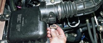
Where is the cooling fan relay on the VAZ-2110
In order for everything to work correctly in the VAZ-2110 engine, it is necessary to maintain a certain temperature.
This temperature range is achieved using a cooling fan, which, as a rule, comes with an electric drive. Its activation and deactivation is carried out automatically. Moreover, if the machine contains a carburetor engine, then TM 108 is used, and in the case when an injection engine is used, a controller is used. This article will tell you where the cooling fan relay is located on a VAZ-2110 car. If the fan is controlled by switching on, it is important that the temperature setting of the housing sensor is observed. The sensor is considered faulty when its temperature has reached the switch-on level, and the cooling motor has not worked. To check, you should close the contacts of the sensor, then check whether the fan works; if so, then the sensor needs to be replaced with a new one.
There are times when closing the contacts does not help and the fan still does not work, then according to the diagram, the integrity of the fuse with the supply wires is checked.
In order to start the cooling fan of the machine in which the injection engine is located, an electronic controller is used. Temperature conditions are pre-entered into the device software and range from 100 to 105 degrees. If the temperature sensor is faulty, then a system error is selected on the controller, and the cooling fan is activated when the car engine is turned on.
A number of breakdowns occur in which the controller does not detect the breakdown, and as a result, when the required temperature reaches 105 degrees, the fan simply does not start. To perform the test, remove the temperature sensor connector while the engine is running. If the system is working properly, the sensor will start the cooling fan, and by returning the connector to its original position, the fan will turn off. In case of damage to the circuit, check the quality of the relay, fuse and underwater wires. Everything must be installed exclusively according to the diagram. To carry out express checks, they bridge terminals 30 and 87 of the fan relay, which are located in the heating shaft. To make it easier to find, look in the passenger seat area.
When the fan is activated, connect the control lamp, the housing and output 86 of the relay, then the relay will operate and the fan will start automatically. At the same time, it is necessary to manipulate such a circuit only when the relay is located in the connector block. Here it is recommended to look at the controller and the wire, the relay connector with pin 46, if there is a breakdown in one of them. If a specific click of the relay did not occur, but a positive signal goes from the main relay to pin 85, or there was a click, but the cooling fan did not start, then this indicates a breakdown of the relay and the need to replace it.
Why are relays needed?
Automotive relays are electromagnets that have a coil and a metal core. They help close many high-current circuits remotely using small buttons.
For example, the starter circuit draws a lot of current when cranking. To turn on the starter you need powerful contacts and a good switch, which is the ignition switch.
When you try to connect a small start button, it will simply burn out. Burnt contacts will not be able to transmit electricity, and therefore are no longer suitable for use. Therefore, in order for the Start-Stop button to work, a relay is used.
So the connection, for example, of an audio signal looks schematically:
As many have noticed, control here is carried out in a negative way.
What do you need to know about relay operation?
Operating voltage
The voltage indicated on the relay body is the average optimal voltage. Car relays are printed with “12V”, but they also operate at a voltage of 10 volts, and will also operate at 7-8 volts. Similarly, 14.5-14.8 volts, to which the voltage in the on-board network rises when the engine is running, does not harm them. So 12 volts is a nominal value. Although a relay from a 24-volt truck in a 12-volt network will not work - the difference is too great...
Switching current
The second main parameter of the relay after the operating voltage of the winding is the maximum current that the contact group can pass through without overheating and burning. It is usually indicated on the case - in amperes. In principle, the contacts of all automotive relays are quite powerful; there are no “weaklings” here. Even the smallest switches 15-20 amperes, standard size relays – 20-40 amperes. If the current is indicated double (for example, 30/40 A), then this means short-term and long-term modes. Actually, the current reserve never interferes - but this mainly applies to some kind of non-standard electrical equipment of the car that is connected independently.
Pin numbering
Automotive relay terminals are marked in accordance with the international electrical standard for the automotive industry. The two terminals of the winding are numbered “85” and “86”. The terminals of the contact “two” or “three” (closing or switching) are designated as “30”, “87” and “87a”.
However, the marking, alas, does not provide a guarantee. Russian manufacturers sometimes mark a normally closed contact as “88”, and foreign ones – as “87a”. Unexpected variations of standard numbering are found both among nameless “brands” and among companies like Bosch. And sometimes the contacts are even marked with numbers from 1 to 5. So if the contact type is not marked on the case, which often happens, it is best to check the pinout of the unknown relay using a tester and a 12-volt power source - more on this below.
Terminal material and type
The relay contact terminals to which the electrical wiring is connected can be of a “knife” type (for installing the relay into the connector of the block), as well as a screw terminal (usually for particularly powerful relays or relays of obsolete types). The contacts are either “white” or “yellow”. Yellow and red - brass and copper, matte white - tinned copper or brass, shiny white - nickel-plated steel. Tinned brass and copper do not oxidize, but bare brass and copper are better, although they tend to darken, making contact worse. Nickel-plated steel also does not oxidize, but its resistance is rather high. It’s not bad when the power terminals are copper, and the winding terminals are nickel-plated steel.
Pros and cons of nutrition
In order for the relay to operate, a supply voltage is applied to its winding. Its polarity is indifferent to the relay. Plus on “85” and minus on “86”, or vice versa - it doesn’t matter. One contact of the relay winding, as a rule, is permanently connected to plus or minus, and the second receives control voltage from a button or some electronic module.
In previous years, a permanent connection of the relay to the minus and a positive control signal was more often used; now the reverse option is more common. Although this is not a dogma - it happens in every way, including within the same car. The only exception to the rule is a relay in which a diode is connected parallel to the winding - here polarity is important.
Relay with diode parallel to coil
A few words about the additional block
In addition to the main unit, there are several protective devices and relays in the additional unit. The designers placed it inside the car on the right side. To get to it you need to unscrew two screws on the side trim of the instrument panel.
This device has three fuses, as well as three electromagnetic relays:
- No. 1 protects the ignition system controller;
- No. 2 refers to sensors that control air flow, oxygen, speed;
- No. 3 is designed to protect elements of the fuel system, pump, injectors, relays;
- No. 4 to turn on the fan;
- No. 5 connection of the fuel pump;
- No. 6 relates to the ignition system.
The devices are blue, which means they are designed for a current of 15 amperes.
Before installing a new device, you should carefully check the protected circuits for short circuits. If this is not done, the installed device will burn out. If you try to install a jumper wire instead, the electrical wires may catch fire or the electronic equipment may fail.
Control circuit modernization
The cooling fan on the top ten turns on at a temperature of 100-105°C, while the normal operating temperature of the engine is 85-90°C, so the fan turns on when the engine overheats, which naturally has a negative effect.
This problem can be solved in two ways: adjust the switch-on temperature in the “brains” or make a button. We'll focus on the second one. Turning on the fan from the button is very convenient: if you get into a traffic jam, turn it on, drive out, turn it off, and no overheating occurs.
A button for selecting the fan operating mode was installed in the cabin (always off, constantly on, automatically turned on via a sensor) - this “tuning” is not mandatory, but will be a very useful addition.
There will be a large current at relay contacts 87, 30, on the wire from the battery to the fuse and the fan ground, and therefore we must use wires there with a cross-section of at least 2 mm, otherwise the thinner wire will not withstand it and will burn out.
What else you should know
The main and additional fuse blocks of the VAZ 21124 do not protect all electrical circuits of the car. If you look closely behind the open main mounting block, you can see a separately located fuse to eliminate problems in the fog lights. There, behind the mounting block in a separate plastic box, there is a fuse that protects the central locking.
But that's not all. Depending on the configuration, in addition to the fact that there is already a fuse block on the VAZ 21124 with 16 valves, there may be protective devices installed in the equipment, for example, in a car radio or alarm system. All this should be taken into account when looking for problems in the vehicle's electrical system. We also recommend watching a video on this topic: