Print this article Font size 16
The fuel-injected 8-valve VAZ 2110 has a wide variety of sensors. Each of them has its own important function, the termination of which can lead to certain consequences.
Mass air flow sensor on VAZ 2110
It is obvious that the injector has long surpassed the carburetor in all respects. If only for the reason that in injectors the electronics are responsible for supplying fuel and air-fuel mixture to the cylinders. Efficiency, economy and a number of other advantages have literally displaced the carburetor from its once leading position.
The presence of a large number of electronics provides an abundant number of sensors. We will talk about some of them today:
- Air regulator sensor;
- Fan switch sensor;
- Crankshaft sensor;
- Coolant temperature sensor;
- Speed sensor;
- Phase sensor.
Now let's look at them in more detail.
A little history
The VAZ 2110 was produced from the end of the 20th century until the middle of the first decade of the 21st century. During its existence, the top ten managed to gain a huge number of fans and underwent a large number of changes.
The tenth VAZ family was initially equipped with 8-valve carburetor engines that had common roots from the G8 engines. Time moved forward and AvtoVAZ needed to develop further, and at the end of the 90s, an injection engine was installed on the top ten for the first time, which was distinguished not only by a new injection system, but also by the number of valves; some new engines received a doubled number of valves from 8- mi to 16.
To operate an engine with an injection system, you need a huge number of different sensors responsible for the operation of the internal combustion engine, and the VAZ 2110 is no exception; the dozens of injection engines have many different sensors installed that ensure correct and smooth operation of the engine.
In this article we will talk about VAZ 2110-12 sensors, their symptoms of malfunction and installation locations.
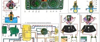
General electrical circuit VAZ-2111
- Block lights;
- Sound signal;
- Engine cooling fan electric motor;
- Starter VAZ-2111;
- Accumulator battery;
- Generator;
- Reversing light switch;
- Electric drive for locking the right front door lock;
- Power window relay;
- Starter activation relay;
- Heater motor;
- Micromotor-reducer for heater damper drive;
- Windshield washer motor;
- Washer fluid level sensor;
- Electric drive for locking the left front door lock;
- Right front door power window switch;
- Electric trunk lock;
- Additional resistor for heater fan motor;
- Windshield wiper gear motor;
- Left front door power window switch;
- Electric power window of the right front door;
- Door lock system control unit;
- Outdoor lighting switch;
- Brake fluid level sensor;
- Electric window lifter of the left front door;
- Indicator lamp for turning on the fog light;
- Fog light switch;
- Instrument cluster;
- Rear window heating indicator lamp;
- Rear window heating switch;
- Understeering's shifter;
- Fog light relay;
- Ignition switch;
- Mounting block;
- Illumination lamp for heater control levers;
- Hazard switch;
- Automatic heater control system controller;
- Glove compartment lamp;
- Glove compartment lamp switch;
- Cigarette lighter;
- On-board control system display unit;
- Ashtray lighting lamp;
- Socket for portable lamp;
- Instrument lighting switch;
- Electric drive for locking the right rear door;
- Right rear door power window switch;
- Watch VAZ-2111;
- Electric window lift of the right rear door;
- Brake light switch;
- Electric window lifter of the left rear door;
- Left rear door power window switch;
- Electric drive for locking the left rear door;
- Side direction indicators;
- Parking brake warning lamp switch;
- Luggage compartment lighting;
- Individual lighting lamp;
- Interior lighting;
- Heating system temperature sensor;
- Switches in the front door pillars;
- Switches in the rear door pillars;
- Exterior tail lights;
- Interior tail lights;
- License plate lights;
- Rear window wiper motor;
- Rear window washer motor;
A — Pads for connecting the right front speaker; B — Pads for connecting audio equipment; B - 110: Blocks for connecting the rear window washer motor; G — Pads for connecting the left front speaker; D — Block for connecting the injection system wiring harness; E - Connector for diagnosing electric power steering; Ж - Connector for diagnosing the automatic heater control system; 3 — Pads for connecting the right rear speaker; I — Pads for connecting the left rear speaker; K - socket for connecting the on-board computer; L - to the electric trunk lock; M — Blocks for connecting additional brake signals; H - to the rear window heating element.
A more detailed diagram of the same thing, consisting of two parts:
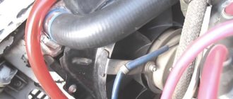
Mass air flow sensor (MAF)
It is one of the most important sensors. The mass air flow sensor is responsible for the formation of the air-fuel mixture. It measures the volume of air supplied to the intake receiver and transmits the readings to the electronic engine control unit, which in turn supplies the right amount of fuel in relation to air. The failure of this sensor affects many different functions of the internal combustion engine.
It should be noted that the “CheckEngine” lamp will light up only if the sensor fails completely. Most often, the sensor undergoes aging, but very rarely fails completely. You can read how to check this sensor in our article.
Signs of malfunction:
- Increased fuel consumption;
- Uneven idle speed;
- Difficulty starting the internal combustion engine;
- Loss of dynamics;
- Jerks when moving;
Cleaning
Quite often you can avoid replacing the mass air flow sensor by simply cleaning this engine element.
You should do the cleaning yourself in this way:
- Remove the pipe from the mass air flow sensor;
- Now remove the sensor from the pipe. Otherwise, high-quality washing will not work;
- To remove the sensor, arm yourself with sprocket keys in advance. Finding such kits is not a problem;
- Unscrew all the fasteners, remove the sensor from the pipe and assess its external condition;
- Often there are traces of oil deposits on the sensor. The purpose of cleaning is to make the device as good as new;
- Carburetor cleaner is often used to clean the air flow sensor;
- Inside the film there are sensors, which are small wires attached to a special resin. These elements must be carefully sprayed with cleaner so as not to damage the devices;
- Wait a while for the surfaces to dry. To speed up the process, use a can of compressed air;
- It is not uncommon to use alcohol instead of carburetor cleaner, which also works quite effectively;
- Proper cleaning of the mass air flow sensor involves treating the pipes from accumulated debris, dirt and dust;
- Having carefully processed all the components of the removed mass air flow sensor, wait until it dries, and then reassemble it. Cleaning is complete.
Spray cleaning Statistics show that in about 80% of cases, simple cleaning can return the mass air flow sensor to its previous functionality.
Price issue
80% is not 100. Therefore, sometimes you have to change the sensor. And to replace it, you need to buy it.
There are three price categories for air mass flow sensors:
- Cheap. These are predominantly Chinese products, the price of which is up to 1000 rubles. It is strongly not recommended to purchase such regulators;
- Average. These include sensors from AvtoVAZ, domestic and some foreign analogues. These cost from 1500 to 2500 rubles;
- Expensive. High-quality, reliable, imported air flow sensors, the price of which can reach 5.5 thousand rubles. It’s hard to say how rational it is to buy them. But they will definitely last a long time.
When choosing a new mass air flow sensor, focus not only on the price, but also on the manufacturer. Today, the most popular devices are from Siemens and Bosch. Average in price, excellent in quality.
Speed sensor
This sensor is designed to transmit readings to the engine ECU about the speed of the vehicle. It is involved in adjusting the engine speed when driving, namely, if the car is rolling in neutral, you will notice that the speed is slightly higher than the idle speed when the car is standing still. The DS is also responsible for the performance of the speedometer and odometer.
Signs of malfunction:
- Inoperative speedometer or odometer;
- There are no increased speeds when driving in neutral gear;
Is the air flow sensor covered? Don't rush to buy a new one
A new sensor costs from 2 to 3.2 thousand rubles. But before we run to the nearest store or car market, let’s try to bring the old one back to life. This method of resuscitation does not provide a 100% guarantee of restoration of functionality. But it's worth a try.
First, disconnect the negative terminal on the battery. Remove the sensor from the vehicle. Remove it from the air filter housing. Disassemble the device using a Phillips screwdriver. Be careful with platinum threads, do not touch them with your hands or other objects. Clean with carburetor cleaner. Spray the liquid 3-4 times onto the areas indicated by arrows in the photo. Assemble the mass air flow sensor and install it on the car.
Coolant temperature sensor (DTOZH)
The DTOZH is installed in the thermostat housing and transmits readings to the ECU about the temperature of the engine coolant. Based on these readings, the engine control unit increases or decreases engine speed for more stable operation of the internal combustion engine. The operation of this sensor is noticeable on a cold engine; when starting the engine in the cold season, you can notice increased speed, which decreases over time as the engine warms up to operating temperature.
Signs of malfunction:
- Increased fuel consumption;
- Poor starting on a cold engine;
- Lack of warm-up speeds;
Principle of operation
The mechanism of action of the temperature sensor on the VAZ 2110–2112 family is based on changing resistance parameters depending on the ambient temperature t°C. In essence, we have before us an electronic resistor with a negative temperature coefficient. That is, the lower the t°C, the higher the resistance of the device, and vice versa.
Table 1. Operating temperatures and parameters of DTOZH
| Temperature, t°C | Resistance, Ohm |
| 100 | 177 |
| 40 | 1459 |
| 25 | 2796 |
| 9420 | |
| −20 | 28680 |
| −40 | 100700 |
The presented values can be used to check the sensor with a tester. More on this below.
What function does DTOZH perform in the ECU system?
There is no damper (choke) on injection machines. Now the fuel is enriched or leaned by the control unit using the t°C values coming from the DTOZH. In addition, the main controller monitors the operating temperature of the engine and gives a command to turn on the fan if it overheats.
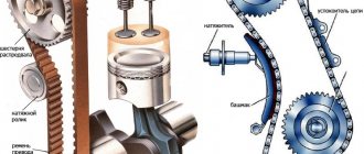
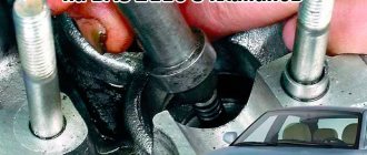
Crankshaft position sensor (CPS)
DPKV is a sensor that counts crankshaft revolutions. Just like most sensors, it participates in the formation of the fuel mixture. If it malfunctions, the car will not start.
The sensor is installed on the rear of the engine under the oil filter. Works in tandem with the crankshaft pulley (generator drive).
Signs of malfunction:
- The car does not start (no spark);
- Jerks when moving;
- Spontaneous engine stop;
Phase sensor (PF)
This sensor is necessary for counting camshaft revolutions; its functions are similar to those of the DPKV. Designed for phased fuel injection; without this sensor, the internal combustion engine will operate in emergency mode and the fuel supply will switch to pairwise mode.
It is installed under the timing cover on 16-valve engines, and on 8-valve engines on the end of the cylinder head on top of the thermostat.
Signs of malfunction:
- Increased fuel consumption;
- Unstable work at XX;
- Loss of dynamics;
Idle air control (IAC)
This sensor is installed on the throttle valve and regulates the air supply when the car is running at idle. In other operating modes of the internal combustion engine, the idle air regulator is not involved. The sensor performs mechanical functions, so if it malfunctions, the “CheckEngine” warning light does not light up.
If the regulator breaks down, you can wash it and try installing it again. If washing does not help, the sensor must be replaced with a new one.
Signs of malfunction:
- Unstable idle;
- The engine stalls when coasting;
- Difficulty starting the engine;
- Low speed XX;
Cleaning DXX
You cannot ignore such a basic procedure as cleaning - this can give results, since sometimes parts of the product, contacts, become coked, covered with dirt and oil.
What you need for cleaning:
- cleaner (lubricant) WD-40 or similar cleaning products for equipment;
- cotton wool, clean rags, tampons.
- The sensor is completely dismantled, with the block disconnected.
- The swab is moistened with the cleaning mixture. You can also spray the product with an aerosol.
- Carefully wipe the contacts, needle, and installation sites, especially if oil is found there.
Before installation, the regulator is dried, the protrusion of the needle from the body is measured (the norm is 23 mm).
If the sensor has a malfunction of the electrical part - the winding, the electric motor - then repair is impractical or impossible. They buy a new product, especially since it is not too expensive (on average 500–700 rubles, but can be found for 250–300 rubles).
If the problem is in the block with wires (you can buy a new one), loose contacts or contamination, then repair is advisable. Repair also makes sense if there are serviceable parts of an identical product - you can disassemble it and try to replace these parts. But we must take into account that usually such a repaired device breaks down more often and the inconvenience caused by this will be very unpleasant, so it is usually more profitable to immediately buy a new product.
Throttle Position Sensor (TPS)
TPS is designed to transmit indications about the position of the valve in the throttle assembly. The received readings are transmitted to the ECU for further regulation of the fuel mixture. This sensor fails quite often. Located on the throttle valve above the IAC.
The sensor cannot be repaired and if it breaks, it is replaced with a new one.
Signs of malfunction:
- Spontaneous increase and decrease in speed;
- Difficulty starting the engine;
- Increased fuel consumption;
- Low speed XX;
Oil pressure sensor (OP)
This sensor signals the condition of the oil pressure in the engine. When it decreases, a lamp on the car’s dashboard lights up in the form of a red oil can. The sensor is completely mechanical and is only responsible for turning on the low oil pressure indicator.
Signs of malfunction:
- The oil pressure lamp does not light up;
- The oil pressure lamp is constantly on;
Gasoline level indicator
The fuel sensor of the VAZ-2110, like any other car, is a rheostat made of nichrome wire. Its moving contact is mechanically connected to a float, which is located in the tank on the surface of the gasoline. The fuel level changes, and along with it the resistance of the rheostat, which is recorded by the device on the panel.
In addition, there is an indication of the reserve amount of gasoline. It works thanks to the same float. In a certain position, it closes the contacts, which causes the warning lamp to turn on. The fuel gauge cannot be called an accurate and reliable device. However, these are the disadvantages of all mechanical sensors. The main malfunctions are associated with damage to the nichrome wire, which simply wears out due to the constant movement of the “runner”.
The sensor is naturally installed in the tank, and replacing it does not present any difficulties. True, you will have to remove the fuel pump and partially drain the fuel if the car is “filled to capacity.”
Oxygen sensor (OS)
The VAZ 2110 oxygen sensor is installed in the exhaust manifold. The DC measures the exhaust gases and uses their readings to determine the ratio in which the fuel mixture is formed. If the readings exceed the permissible values, the ECU adjusts the air-fuel mixture in such an amount that the exhaust gases do not exceed the permissible values.
Signs of malfunction:
- Increased fuel consumption;
- Loss of vehicle dynamics;
- Black smoke when driving at high speeds;
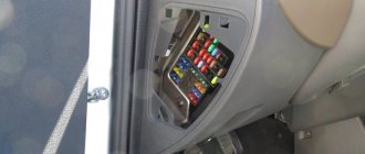
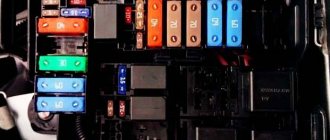
Fuse and relay box
The VAZ-2111 relay and fuse mounting block is located on the left side of the steering column in the instrument panel. To access the unit, press the latch switch and lower the unit down.
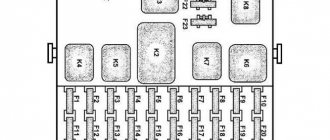
K1 - lamp health monitoring relay;
K2 - windshield wiper relay;
KZ - relay-interrupter for direction indicators and hazard warning lights;
K4 - headlight low beam relay;
K5 - headlight high beam relay;
K6 - additional relay VAZ-2111;
K7 — relay for turning on the heated rear window;
K8 - rear fog lamp relay;
F1-F20 - fuses
| Number | Current, A | Description of fuses |
| F1 | 5 | License plate lamps. Instrument lighting lamps. Side light indicator lamp. Trunk light. Left side marker lamps |
| F2 | 7,5 | Left headlight (low beam) |
| F3 | 10 | Left headlight (high beam) |
| F4 | 10 | Right fog lamp |
| F5 | 30 | Door window motors |
| F6 | 15 | Portable lamp (socket) VAZ2111 |
| F7 | 20 | Engine cooling fan electric motor. Sound signal |
| F8 | 20 | Rear window heating element. Relay (contacts) for turning on the heated rear window |
| F9 | 20 | Recirculation valve*. Windshield and headlight cleaners and washers (wiper protection). Relay (coil) for turning on the rear window heating |
| F10 | 20 | Spare |
| F11 | 5 | Starboard side marker lamps |
| F12 | 7,5 | Right headlight (low beam) |
| F13 | 10 | Right headlight (high beam). High beam warning lamp |
| F14 | 10 | Left fog lamp |
| F15 | 20 | Electrically heated seats. Trunk lock lock |
| F16 | 10 | Relay-breaker for direction indicators and hazard warning lights (in hazard warning mode). Hazard warning lamp |
| F17 | 7,5 | Interior lighting lamp. Individual backlight lamp. Ignition switch illumination lamp. Brake light bulbs. Clock (or trip computer) |
| F18 | 25 | Glove box lighting lamp. Heater controller (heater fuse). Cigarette lighter fuse for VAZ 2110, VAZ 2111, VAZ 2112. |
| F19 | 10 | Locking door locks. Relay for monitoring the health of brake light lamps and side lights. Direction indicators with warning lamps. Reversing lamps. Generator excitation winding. On-board control system display unit*. Instrument cluster. Clock (or trip computer) |
| F20 | 7,5 | Rear fog lamps |
A fog lamp fuse is installed in the niche of the instrument panel behind the mounting block. The central locking fuse is located behind the fuse box in a plastic box. And additional relays and fuses (all 15 A) are located in the cabin on the right side of the instrument panel behind the side trim attached with two screws.
- 1 — ignition module, controller;
- 2 — canister purge valve, vehicle speed sensor, oxygen concentration sensor (heating), air flow sensor VAZ-2111;
- 3 - fuel pump relay, fuel pump fuse, injectors.
- 4 — electric fan relay;
- 5 - fuel pump relay,
- 6 - main relay (ignition relay).
Relay and fuse box diagram
This is a schematic diagram of the VAZ 2111 relay and fuse mounting block. The outer number in the wire tip designation is the block number, and the inner number is the conventional number of the plug.
| Block | № | Color | Electrical circuits |
| Ш1 | 1 | ZhCh | fog lamp (left) |
| 2 | GP | trunk lock motor, heated seats | |
| 3 | R | door lock relay | |
| 4 | ABOUT | power window relay | |
| 5 | ZhP | fog light relay | |
| 6 | AND | fog lamp (right) | |
| 7 | MS | power window relay | |
| 8 | — | reserve | |
| Ш2 | 1 | — | reserve |
| 2 | — | reserve | |
| 3 | — | reserve | |
| 4 | H | weight " - " | |
| 5 | ZhP | size (left rear) | |
| 6 | Warhead | outdoor light switch | |
| 7 | — | reserve | |
| 8 | ZhCh | license plate lamps, off instrument lighting | |
| 9 | KP | size (right rear) | |
| 10 | TO | size (right) | |
| 11 | ZhG | email windshield wiper motor, windshield wiper and washer switch. | |
| 12 | Z | outdoor light switch | |
| 13 | ABOUT | fog light switch | |
| 14 | Emergency | hazard switch | |
| 15 | — | reserve | |
| 16 | GP | Ignition switch (terminal 15), steering column switch | |
| 17 | R | windshield wiper and washer switch | |
| 18 | JV | steering column headlight switch | |
| 19 | — | reserve | |
| 20 | — | reserve | |
| 21 | AND | size (left) | |
| Ш3 | 1 | midrange | low beam (left headlight) |
| 2 | — | reserve | |
| 3 | WITH | low beam (right headlight) | |
| 4 | R | generator (cl. 30) | |
| 5 | TO | generator (cl. 30) | |
| 6 | TO | generator (cl. 30) 2111 | |
| Ш4 | 1 | PZ | on-board display system |
| 2 | GO | hazard switch | |
| 3 | IF | hazard switch | |
| 4 | H | weight " - " | |
| 5 | PG | portable lamp plug | |
| 6 | Salary | heated rear window switch, heated rear window lamp | |
| 7 | — | reserve | |
| 8 | — | reserve | |
| 9 | — | reserve | |
| 10 | ZhZ | steering column washer and windshield wiper switch | |
| 11 | B | email windshield wiper motor | |
| 12 | BW | steering column washer and windshield wiper switch | |
| 13 | GB | steering column switch, ignition switch lamp | |
| 14 | BP | brake lights, clock, interior lamp | |
| 15 | P | brake lights | |
| 16 | RP | off brake lights | |
| 17 | ABOUT | generator (cl. 30) VAZ-2111 | |
| Ш5 | 1 | AF | high beam (left lamp) |
| 2 | JV | rear window heating element | |
| 3 | G | heater controller, glove compartment lamp | |
| 4 | Z | high beam (right lamp) | |
| 5 | ZhG | Windshield wiper motor, SAUO recirculation valve | |
| 6 | PB | email cooling fan, beep |
To locate the faulty fuse, use the table of circuits protected by fuses. Before this, of course, you need to find the cause of the blown fuse, eliminate it, and only then install a new one. The table shows the circuits that each fuse protects, but on each model some of them may not be installed due to the lack of certain devices (for example, power windows, lock drives and other units).