I feel soon my blog will turn into a manual for repairing Lada electrical equipment... =/
In general the situation is like this:
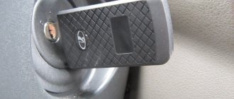
The turn signals on the car did not always work. Then they stopped altogether. When you turn on the turn signals, the light on the dash tries to blink, but nothing. The relay clicks.
So what if it clicks, I thought, and checked its functionality. I checked it by adding a new relay. And voila.
Only one thing confused me...
To the relay was insolent
Some kind of third-party wiring is attached. The owner was unable to find out its purpose.
For additional information to potassium growers:
I went to find out - it became interesting: 1) The principle of operation (yes - I didn’t know, I confess); 2) What could this wiring do there; 3) How can this relay be used in Solaris =)
1) Operating principle:
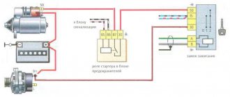
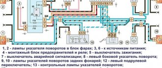
The turn relay has 3 contacts: 49, 49a and 31. 31 contacts - constant ground (-) 49 contacts - constant power (+) 49a contact - relay control.
When contact 49a was closed through the load (Light bulb/speaker/LED, etc.) to ground, the relay began to operate.
On Kalina, contact 49a goes to the emergency lights and turn signals. To the emergency lights, from this contact, the wiring goes without a break. Accordingly, the relay turns on without ignition.
Turn signals 49a receive contact only after the ignition is turned on.
This point was sorted out (personally, for myself, I understood everything I wanted). If you have any questions, I will be happy to answer them.
2) I still haven’t realized the meaning of this wiring. In fact, it was connected to the load. Accordingly, whatever was connected there, it made the relay work. Or vice versa. Perhaps they wanted a permanent plus. Perhaps they wanted a lot. But without thinking through his actions, the person spent extra money and time fixing the problem.
3) It was at this point that my imagination began to work, because for so long I had wanted to make myself a central brake light (additional, on the trunk lid), which would work in two modes) The circuit is insanely simple, reliable and interesting. So far I have not grown up to soldering microcircuits and programming them. That's why I invent what I have.
Current after the brake pedal, which goes to additional. stop, distributed with a relyushka. If no current is supplied to the relay, add. the signal works as standard.
If you apply current to a 5-pin relay (Relay (5)), which will be controlled by a button from the interior, then contacts 30 and 87 will close. The current (12V) will go to the turn signal relay (Relay (3)) and through it to the additional . light.
To prevent Relay (3) from being killed during normal operation, a diode is placed on leg 49a.
The advantage of this scheme is that in case of malfunction, the cause will only be in the relay. Replacing them is not a problem.
Soon I will try to create a prototype and subsequently install such a feature in my car.
How does an electromagnetic-thermal relay work?
These devices are no longer used in modern cars. However, in older models they are still widely used.
The design of the electromagnetic-thermal relay is quite simple; it uses a circuit for connecting turn signals through an electromagnetic-type relay. It is made in the form of a cylindrical core, and a thin copper wire is used as its winding. At the top of the core there are two groups of contacts, and metal anchors are installed on each side. The first group of contacts closes the circuit where there is a control light located on the instrument panel. With the help of other contacts, the circuit with the lamps in the direction indicators is closed. They are the ones who provide the flashing mode.
What to do if the hazard lights and turn signals stop working
Traffic rules regulate the use of emergency signals and turn signals. If the light signals fail, the driver must indicate the maneuver with hand signals, continuing to move to the parking or repair site.
Thus, if the emergency lights and turn signals stop working, then such a malfunction of the systems is critical; further operation of the car is impossible without eliminating it.
Causes and symptoms of malfunction of hazard and turn signals
All manufacturers pay due attention to the quality and reliability of turn signal and emergency flasher systems for the following reasons:
- road safety largely depends on the performance of these signals;
- light signals, especially when turning in urban traffic, switch from one mode to another most often compared to other systems;
- systems must be built in such a way that the driver knows in real time about their performance (so-called feedback, light and sound).
Depending on the circuit design of the emergency and turn signal systems, the following malfunctions are possible:
- burnout of lamps (main and turn signals);
- malfunction of the LED bars if they are used in the turn signal system;
- malfunction of the turn switch on the steering column (oars, dragonfly - in the slang of car enthusiasts);
- malfunction of indicator lamps on the dashboard and hazard warning switch;
- damage to electrical wiring;
- Malfunction of the body control unit during electronic control of the hazard and light signaling modes.
Video - the hazard lights and turn signals stopped working on the Volkswagen Passat B5:
Considering the importance of the system, manufacturers organize light and sound monitoring to indicate signs of malfunction of emergency lights and turn signals. These include:
- no blinking indicator lights or turn signal LEDs on the dashboard;
- increasing the frequency of blinking of the direction lamps on the dashboard and sound signals in the steering column area;
- absence of sound signals (clicks) in the area of the steering column;
- no blinking of the lamp on the hazard warning indicator.
If turn signals and emergency lights do not work: common faults and their elimination
Turns relay
Until recently, the main element of turn signal and hazard signal systems was the turn relay. In the middle of the last century, turn relays with a bimetallic plate were used. In some models of budget cars and trucks they are still used to this day. Along with simplicity and low cost, they are more reliable and maintainable. A typical relay circuit is shown in the figure:
The core of the circuit is a bimetallic strip. It is included in the circuit of current flow through the turn lamps. When turning on the turns or emergency lights, it is in a non-heated state, and closes the circuit of the warning lights, they turn on. As the bimetallic plate is heated by the flowing current, it changes its geometric dimensions (bends).
Nowadays, combined relays with a built-in electronic circuit are used.
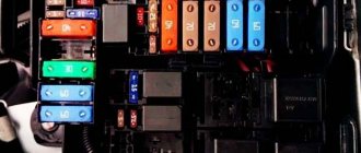
Such circuits are less reliable and often fail, especially from unknown manufacturers. Relays are usually mounted either on the steering column or in the fuse box under the dash.
This is done so that their operation can be heard by the driver. In modern cars, there is an additional buzzer in the dashboard that duplicates the turn indicators.
Such relays cannot be repaired; they must be replaced.
Electronic relay: circuit and principle of operation
The design of the electronic turn signal relay consists of two main parts. From a standard electromagnetic relay that performs switching and an electronic key that provides a certain frequency of operation of this device.
The nichrome string has been replaced with an electronic key. With its help, voltage is supplied and removed from the winding of the electromagnetic relay at certain intervals. The key is based on microcircuits or discrete elements. They are components of the master oscillator and control circuits.
The operating principle of an electronic relay is very simple. When voltage is applied to the relay, the master generator is switched on. With its help, control pulses with different frequencies are generated, which are supplied to the control circuits. By means of pulses, the current passing through the winding of the electromagnetic relay is supplied or interrupted. Such actions cause the anchor to alternately attract or lower. As a result, the contact groups close or open at a certain frequency, ensuring the same flashing of the signal lamps.
All electronic elements of the relay are mounted on a separate board. The electromagnetic relay is located above the board. Both of them are housed in a plastic case. The contacts are brought out from below or from the side. For fastening the housing there are holes and eyes for bolted connections.
Each electronic turn relay has undoubted advantages over other designs. They have proven themselves to be high-quality and technologically advanced devices, manufactured on the basis of modern circuits that are characterized by increased reliability. The technical characteristics of these devices remain unchanged, regardless of the service life.
Work principles
The variety of turn relays is quite large, but they are all divided into two main types:
- classical electromagnetic-thermal relays;
- electronic relays.
Electromagnetic-thermal relays are considered obsolete and can now only be found on very old cars, for example, classic Zhiguli cars. This type of relay consists of a core with a copper winding. There are two contact groups in the upper part of the core, and metal anchors in the sides. The structure is placed in a metal case, in the lower part of which contacts for connecting to the network are output.
When the turn switch is turned on, the network is closed - the lamp does not light. Then one of the anchors, under the influence of the nichrome string in the core, straightens and closes the contacts. After this, the current begins to flow in a bypass circuit, and the lamp lights up at full power. The click of the turn signals is ensured by the impact of a metal armature on the contacts.
An electronic relay consists of two main parts: a classic electromagnetic relay and an electronic key that ensures the frequency of operation of the relay. In a relay of this type, the operating principle of the nichrome string, which ensures the closure of the contacts, is assigned to a separate circuit board (key). Otherwise, the operation scheme is similar: the flowing current closes the contacts, after which the indicator lamps and the light on the dashboard light up. Interruption of the current leads to lowering of the armature and opening of the contacts - the indicator lamps go out. A characteristic click is also provided by the impact of the armature on the contacts.
Turn signal relay pinout
During operation, the standard turn relay may fail and in this case it needs to be replaced. Incorrect operation of the device becomes noticeable, especially when the control light stops lighting up. The main cause of the malfunction is incomplete closure of the device.
In other cases, the relay begins to function unstably, and the relay contacts close at different time intervals. In some cases, the volume level of the sound accompanying the operation of the device is significantly reduced. This can create a serious problem on the road when the device is activated without the driver noticing due to accidental contact while driving the vehicle.
These shortcomings are eliminated by replacing the standard device with an electronic design. In this case, the turn signal relay is connected according to the standard diagram shown in the figure. Pin No. 1 is positive, the second pin connects to the turn switch, the third connects to the warning light, and the fourth connects to ground.
All connections and contacts must be reliably insulated using electrical tape and cambric, which is a hollow plastic braid. This eliminates possible short circuits with other conductors. Certain inconveniences are created by the plastic housing of the electronic relay, which does not always fit in its standard location. However, home craftsmen quite easily overcome this difficulty and find the most optimal technical solution.
DIY turn relay
Sometimes situations arise when the standard turn signal relay fails and it is not possible to purchase a new device. In such a situation, you can try to make a turn signal relay with your own hands to provide the car with the necessary signals. The simplest electronic devices that you can create yourself are simple and easy to use, operate smoothly and reliably. High accuracy is achieved through the use of PWM controllers used in all circuits.
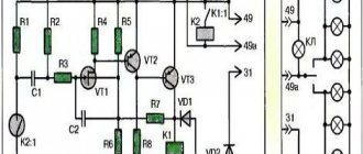
The simplest replacement for an electromagnetic relay is designed for a maximum load power of 150 W. It is connected to the positive terminal. If the IRFZ44 field switch is replaced with the IRF3205 model, then 200 W can be connected. This simple circuit ensures high accuracy of operation. The blinking frequency does not depend on the power of the light bulbs, so LED, halogen and other lamps can be included in the circuit.
The frequency of flashing is directly related to the capacitance of the capacitor. As the capacity increases, the light bulb will blink more rarely, and, conversely, decreasing the capacity will lead to faster blinking. The low-power 1n4148 diode can be replaced by any similar element. When the circuit reaches a power of 80 W, a slight generation of heat is observed in the field-effect transistor area. This means it is ready to use.
There is another simple circuit of a turn relay with a coil - simple, reliable and inexpensive. It is capable of lighting both regular light bulbs and LED ones and is designed for 12 V. The contacts are connected according to the principle of a regular switch, that is, in series with the light bulb. The LED is installed in the circuit as an indicator during commissioning work. The device parameters are adjusted by changing the resistance of the resistor.