Let us remind you that the emergency signaling is carried out by the same electrical circuit that turns on the direction indicators. Therefore, it is possible that problems in the electrical circuit will be similar. But before we start talking about malfunctions, let’s remember what the electrical circuit of the alarm on the VAZ 2114 looks like and how it turns on. Also from the same article, the reader will learn how to move the emergency button from under the steering wheel to the dashboard and install an elegant Euro button.
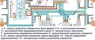
Emergency gang diagram for VAZ 2114
Electric current from the power source (3) enters the mounting block (4), where it passes through two fuses and a relay to buses 2 and 4 through the X11 chip of the mounting block. From the mounting block, the wires go to the ignition switch and hazard warning switch, which has several modes. There is another turn signal switch in the electrical circuit, which is called the left steering column switch (12). The turn signal headlights in the diagram are indicated by numbers:
- 1,2 – front,
- 8, 11 – side,
- 9.10 – rear.
Useful: Where
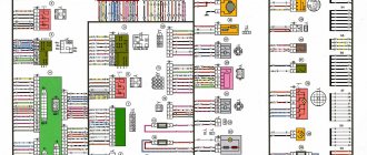
To complete the picture, we provide, as an illustration, a diagram of the location of fuses and relays in the mounting block.
SF Manual: Emergency Light Alarm (“Hazard Light”) for VAZ 2101-03
- Log in to reply to this topic
#21 Oleg S
- Users
- Posts: 2
- Top
- Name or Quote
In this material I will try to help owners of classic Lada models 2101, 2102 and 2103 acquire such a useful and necessary thing as an Emergency Light Alarm, or in common parlance - an emergency gang! For some reason, the manufacturer itself deprived these models of this device. But the problem can be solved. Searching for solutions on the Internet only led to advice to take circuits 2101 and 2106 and do the same. But not everyone has these two diagrams at hand, and many simply don’t want to figure out what’s there and how. I will present the finished version with pictures and photographs. I have not found such material.
First, we remove the instrument cluster in order to get to the turn relay https://avtoportal.ru. _1268006242.jpg
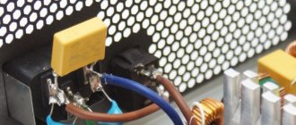
And remove the old relay (looks like a silver barrel) https://avtoportal.ru. _1268006443.jpg
three wires are connected to it: purple, blue and double orange https://avtoportal.ru. 7032010_032.jpg
We mark and secure the wires so as not to lose them
Next, we take a new relay (I recommend 494.3747 as a more modern digital one, as opposed to the analog 231.3747) https://avtoportal.ru. _1268006245.jpg
To connect the relay, I used a six-pin block of suitable shape, using four contacts in it https://avtoportal.ru. _1268006247.jpg
Next you need to “untie” the wires! To do this, I drew a picture, using the example of which I will try to explain what to connect where https://avtoportal.ru. _1268006257.jpg
contact 1 - from here the wire will go to contact 4 of the emergency flasher button contact 2 - here we connect the purple wire removed from the old relay contact 3 - blue wire from the old relay contact 4 - “ground”, we make a wire with a round terminal at the end, fix it on the mounting stud relay.
Next, let's move on to the button! I used a six-pin button (I don’t remember the designation from the catalogue) https://avtoportal.ru. _1268006256.jpg
To connect the button you need to find the right three-link block, I took the wires to the button from it. connected to the block coming from the under-panel braid, and not from the three-lever. https://avtoportal.ru. _1268006251.jpg
here we connect in this way: contact 1 of the button - to the blue wire of the three-lever block; contact 2 of the button - here we connect the double orange wire from the old relay, having first extended its contact; contact 3 of the buttons - to the blue and black wire on the block of the three-lever; contact 4 of the button - to contact 1 on relay pins 5 and 6 are missing on the button! pin 7 of the button - to the purple wire on the three-lever block pin 8 - here we pull a constant “plus”, connect on the fuse block to the wire on which there is voltage even when the ignition is off, it is advisable to “hang” an 8-amp fuse on this wire.
We select the length of all wires according to the installation location of the emergency light switch off button, and stretch the entire braid there https://avtoportal.ru. _1268006254.jpg
The button can be connected either by placing the terminals directly on it, or through a special block. then we collect everything, install the panel and enjoy the blinking of the emergency lights!
I hope this material will help you achieve your plans. And I wish to use the emergency lights more often to “say” thank you to the driver who gave way to you, rather than to indicate a car that has broken down on the road
#22 Shade
1. if you make a high-quality mass, it won’t blink! 2. if you can’t make a mass, take a 12-V LED and insert it instead of a lamp (solve the problem of soldering and choosing a diode), but there may be other problems with heating and wiring burnout, so you’ll have to go back to point 1. good luck
In order not to mess with the buttons, I can suggest another option for installing the emergency lights.
The relay will be used from the front wheel drive and the hazard warning button as well
- Top
- Name or Quote
#23 Oleg S
1. if you make a high-quality mass, it won’t blink! 2. if you can’t make a mass, take a 12-V LED and insert it instead of a lamp (solve the problem of soldering and choosing a diode), but there may be other problems with heating and wiring burnout, so you’ll have to go back to point 1. good luck
In order not to mess with the buttons, I can suggest another option for installing the emergency lights.
The relay will be used from the front wheel drive and the hazard warning button as well
Thanks for the advice. Relay for a front-wheel drive car? I'd like to see the option.
added after 4 minutes 20 seconds but there may be other problems with heating and wiring burnout, so we’ll have to go back to point 1. - does this mean the wires are connected incorrectly?
- Top
- Name or Quote
#24 Shade
- Top
- Name or Quote
#25 sanyok
1. if you make a high-quality mass, it won’t blink! 2. if you can’t make a mass, take a 12-V LED and insert it instead of a lamp (solve the problem of soldering and choosing a diode), but there may be other problems with heating and wiring burnout, so you’ll have to go back to point 1. good luck
- Top
- Name or Quote
#26 serega365
- Top
- Name or Quote
#27 Maryan
- Top
- Name or Quote
Connection diagram for Euro button on VAZ 2114
The figure shows a diagram of connecting turn signals and emergency lights with a new Euro button.
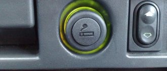
The location of the original emergency button caused a lot of complaints from car owners.
The AvtoVAZ emergency flasher has another significant drawback - its tendency to stick. That is, you turn it on, but how to turn it off is a problem. You have to arm yourself with tools, remove the button from under the steering wheel and fix the loose fastener. This is what causes the sticking.
Useful : The emergency lights and turn signals on the VAZ 2114 do not work
Fortunately, the same engineers provided one slot for a button on the dashboard. Obviously, they left this slot for installing additional equipment in case the car owner wants to modernize the interior, or do tuning in it, and add some cutting-edge device. For now, this nest is closed with a plug (pseudo-button). Almost all car owners bring their emergency lights here, since pressing on them here is much more convenient than somewhere under the steering wheel.
At the beginning of the section there is a diagram of the VAZ 2114 emergency gang, according to which the Euro button will be redone. First, at the nearest car market or in an online store that sells spare parts, we find the Euro button.
You will also need a four-pin relay with a connector (with a block). First, the old button must be dismantled and the wires removed from it. We won't need it anymore. And the wires with contacts will still serve. For ease of connection, the wires can be labeled. Below is a diagram for connecting an emergency light on a VAZ 2114. The diagram shows how to move the wires from the old button to the new one and connect a four-pin relay.
In accordance with the diagram of the emergency signal button on the VAZ 2114, the wires are transferred to the new button and connected to a four-pin relay.
You will get a kind of garland of wiring and devices. This garland is to be mounted in the dashboard of the car. The chip from the old button is removed and the ends of the garland are inserted into its connectors.
If everything was done correctly, the button will work. Now you have to insert the button in place of the plug and remove the wires under the dashboard. By the way, the minus is taken from the minus of the on-board computer. To insert the emergency signal chip into its place, the wires will have to be disconnected for a while. The wiring harness runs from the steering column under the on-board computer. To do this, you will have to remove the corresponding casings and shields. Then the wire terminals are inserted into the connectors again. accidents
What to do with the hole from the old button? Car owners solve this problem in different ways. Some people find a casing of the appropriate size, but without a hole for the button, while others install a plug that matches the color of the casing. On the euro button itself there is a red indicator light, by which you can understand that the emergency lights are on. In addition, when the emergency lights are on, both turn signal arrows on the dashboard flash. The network offers other options for installing the Euro button. For example, with connecting diodes. But in this case, the turn signals light up when the ignition is off, which is not very convenient. The basis is this wiring diagram for the Euro emergency flasher button of the VAZ 2114
To get to the standard button, remove the casing. We take out the old button, its upper part can be thrown away, the spring is not needed. The lower part remains. Through the side wall removed from the driver's side, we pull out the chip with wires under the on-board computer. Here, too, the partition is removed. The wires are soldered in the following order:
- We connect contacts 4 and 8 through an additional wiring;
- The cathodes from the diodes are connected to contacts “1” and “3” by soldering, and the anodes are soldered together;
- The wires of the Euro button with contacts “D” and “2” are connected by soldering to the free anodes of the diodes.
- There is an indicator on the Euro button, but the light bulb is not inserted into the dashboard. It is necessary to insert the light bulb and connect wire 2 to the dashboard;
- The wire of contact “1” on the button is connected to wire 7 on the wiring harness;
- Contacts “A” and “B” are routed to ground and backlight, respectively. To do this, the terminals with wiring must be soldered to contacts A and “B”.
- The resulting wiring harness is connected to the supply line.
To ensure reliable soldering, the contact surfaces are treated with LTI-120 soldering flux;
Installation and configuration instructions
Installing emergency lights on a VAZ 2101 is not a particularly difficult task; almost anyone can cope with it. To properly connect the emergency lights to a VAZ 2101 with your own hands, you need to prepare everything you may need to complete the task.
Set of tools and materials
So, what you need to prepare before starting the process:
- Locksmith tools, including wrenches, screwdrivers, pliers, etc.
- Insulating tape.
- Four-contact light signal relay from the “Six”.
- Six-pin button for activation.
- Five meters of installation wire (video by Alex Gordon).
Work execution algorithm
So, let's start the process:
- First you need to remove the center console. To do this, you need to unscrew the bolts that secure the trim to the steering column. You will also need to remove the side trims of the windshield pillars.
- Having done this, you can remove the instrument cluster. Be careful not to damage the device.
- Next, disconnect the wires from the light bulb that illuminates the glove compartment. Then unscrew the bolts that secure the sides of the glove compartment to the control panel, as well as the bolts that secure its lower part. After unscrewing all the screws, the glove compartment itself can be removed.
- Now you need to remove the screws that secure the bottom of the dash to the front cross member. Then the nuts of the upper fastening are unscrewed; it is best to reach them through the technological opening of the glove compartment.
- After completing these steps, you can remove the handles from the stove control panel. To do this, at the junction of the lever with the handle, use a screwdriver to bend the lower part of the upper handle, and at the lower handle, you need to bend the upper part.
- Next, you need to disconnect the connectors with wires from the control panel backlight switches, side lights, and also the stove. Then, using a wrench, you need to unscrew two more bolts that secure the fastenings of the stove control levers. After completing these steps, you will be able to dismantle the control panel.
- Now let's move on to installing and connecting the main elements. First, decide on the location of installation of the system power button. It should be installed on the center console so that the driver can reach it as quickly as possible if necessary. It’s still too early to install the button, but you need to decide on the installation location now, since this will determine how much wire you need. Now remove the old turn signal relay from the car and disconnect the three cables from it - usually they are colored black, gray-white and orange.
- Next, take a new six-wheel relay. The second contact of the relay must be connected to the wire that was removed from contact L on the turn signal relay, as well as to output 7 of the button.
- The first contact of the relay must be connected to the fourth contact on the button itself. The third contact is connected to the cable disconnected from contact P on the turn signal relay. Then you need to connect the cable from the fourth contact to ground, that is, the body of the vehicle - it is best to connect it to the relay fixing nut.
- The next step is to connect the button itself. The fourth contact of the button should be connected to the first contact of the relay used. Its second contact must be connected to the cable that was disconnected from the positive contact of the rotary relay. The seventh contact is connected to the second contact of the relay, and the first and third contacts are connected to the steering column turn signal switch; in this case, the order of connection does not matter.
- Now all you have to do is connect the eighth pin to any positive cable; alternatively, you can wedge it into the electrical circuit from the cigarette lighter. If you decide to connect the plus directly to the battery or generator unit, the circuit will need to be protected with a fuse.
- At this point, the installation procedure can be considered complete. All you have to do is securely fix the wiring to prevent chafing of the cables. Reinstall all previously removed interior trim elements, center console, glove compartment, etc.
We recommend: Repair and adjustment of headlights from A to Z for owners of Kia Cerato 2007 and Sid