I feel soon my blog will turn into a manual for repairing Lada electrical equipment... =/
In general the situation is like this:
The turn signals on the car did not always work. Then they stopped altogether. When you turn on the turn signals, the light on the dash tries to blink, but nothing. The relay clicks.
So what if it clicks, I thought, and checked its functionality. I checked it by adding a new relay. And voila.
Only one thing confused me...
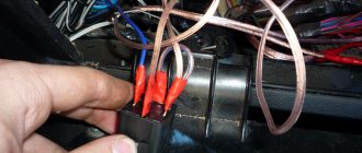
To the relay was insolent
Some kind of third-party wiring is attached. The owner was unable to find out its purpose.
For additional information to potassium growers:
I went to find out - it became interesting: 1) The principle of operation (yes - I didn’t know, I confess); 2) What could this wiring do there; 3) How can this relay be used in Solaris =)
1) Operating principle:
The turn relay has 3 contacts: 49, 49a and 31. 31 contacts - constant ground (-) 49 contacts - constant power (+) 49a contact - relay control.
When contact 49a was closed through the load (Light bulb/speaker/LED, etc.) to ground, the relay began to operate.
On Kalina, contact 49a goes to the emergency lights and turn signals. To the emergency lights, from this contact, the wiring goes without a break. Accordingly, the relay turns on without ignition.
Turn signals 49a receive contact only after the ignition is turned on.
This point was sorted out (personally, for myself, I understood everything I wanted). If you have any questions, I will be happy to answer them.
2) I still haven’t realized the meaning of this wiring. In fact, it was connected to the load. Accordingly, whatever was connected there, it made the relay work. Or vice versa. Perhaps they wanted a permanent plus. Perhaps they wanted a lot. But without thinking through his actions, the person spent extra money and time fixing the problem.
3) It was at this point that my imagination began to work, because for so long I had wanted to make myself a central brake light (additional, on the trunk lid), which would work in two modes) The circuit is insanely simple, reliable and interesting. So far I have not grown up to soldering microcircuits and programming them. That's why I invent what I have.
Current after the brake pedal, which goes to additional. stop, distributed with a relyushka. If no current is supplied to the relay, add. the signal works as standard.
If you apply current to a 5-pin relay (Relay (5)), which will be controlled by a button from the interior, then contacts 30 and 87 will close. The current (12V) will go to the turn signal relay (Relay (3)) and through it to the additional . light.
To prevent Relay (3) from being killed during normal operation, a diode is placed on leg 49a.
The advantage of this scheme is that in case of malfunction, the cause will only be in the relay. Replacing them is not a problem.
Soon I will try to create a prototype and subsequently install such a feature in my car.
How does an electromagnetic-thermal relay work?
These devices are no longer used in modern cars. However, in older models they are still widely used.
The design of the electromagnetic-thermal relay is quite simple; it uses a circuit for connecting turn signals through an electromagnetic-type relay. It is made in the form of a cylindrical core, and a thin copper wire is used as its winding. At the top of the core there are two groups of contacts, and metal anchors are installed on each side. The first group of contacts closes the circuit where there is a control light located on the instrument panel. With the help of other contacts, the circuit with the lamps in the direction indicators is closed. They are the ones who provide the flashing mode.
P O P U L A R N O E:
Using inexpensive and accessible chips NE555, LM3915 and 7805, you can make a simple engine speed tachometer for a car using 10 LEDs.
The LED tachometer can be used for a car with an on-board voltage of 12V or 24V.
Not all cars are equipped with electronic voltmeters. And this is quite a necessary device in a car. It allows you to monitor the charging and condition of the battery. This is very important, especially in winter. Read more…
When I go out by car, I take my laptop with me...
One day I came across an article on an amateur radio website about how to make a car adapter for a laptop.
A simple circuit (see below) - one microcircuit and a pair of transistors...
All drivers are required to indicate maneuvers on the road by turning on the direction indicator. This flashing signal is found in every car. Its operating mode creates a turn relay, the circuit of which supplies current to the light bulbs and causes them to blink. At the same time, an audible signal sounds in the form of clicks, reminding you that the direction indicator is on. All these actions are provided by a special turn relay circuit.
Among various designs, electromagnetic-thermal and electronic relays are most widespread. The latest devices are considered more modern and are installed on all later car models.
Electronic relay: circuit and principle of operation
The design of the electronic turn signal relay consists of two main parts. From a standard electromagnetic relay that performs switching and an electronic key that provides a certain frequency of operation of this device.
The nichrome string has been replaced with an electronic key. With its help, voltage is supplied and removed from the winding of the electromagnetic relay at certain intervals. The key is based on microcircuits or discrete elements. They are components of the master oscillator and control circuits.
The operating principle of an electronic relay is very simple. When voltage is applied to the relay, the master generator is switched on. With its help, control pulses with different frequencies are generated, which are supplied to the control circuits. By means of pulses, the current passing through the winding of the electromagnetic relay is supplied or interrupted. Such actions cause the anchor to alternately attract or lower. As a result, the contact groups close or open at a certain frequency, ensuring the same flashing of the signal lamps.
All electronic elements of the relay are mounted on a separate board. The electromagnetic relay is located above the board. Both of them are housed in a plastic case. The contacts are brought out from below or from the side. For fastening the housing there are holes and eyes for bolted connections.
Each electronic turn relay has undoubted advantages over other designs. They have proven themselves to be high-quality and technologically advanced devices, manufactured on the basis of modern circuits that are characterized by increased reliability. The technical characteristics of these devices remain unchanged, regardless of the service life.
Search for a new relay
If the option of repairing a broken relay does not suit you, then you should immediately start looking for a new device. In fact, this solution is the simplest and most reliable, although it will not satisfy the car enthusiast’s inquisitive mind and desire for experimentation. A new relay costs little money, and on the modern auto parts market it will not be difficult to find a suitable analogue. You can search by:
- VIN code of the car;
- The code of the existing and failed relay or the codes of its analogues;
- Auto parameters.
Practice shows that today motorists are increasingly looking for the necessary spare parts according to the parameters of their vehicle. In particular, the make, model and year of manufacture are important. Modern online stores with their cross-code databases allow you to quickly select both the original relay and its analogues. The selection of relays according to key parameters is special, some of which we indicated in the previous paragraph
. When searching by the parameters of the relay itself, it is easy to make a mistake (or even not find complete documentation at all), but if successful, you will be able to find either the same original or a completely identical analogue.
Turn signal relay pinout
During operation, the standard turn relay may fail and in this case it needs to be replaced. Incorrect operation of the device becomes noticeable, especially when the control light stops lighting up. The main cause of the malfunction is incomplete closure of the device.
In other cases, the relay begins to function unstably, and the relay contacts close at different time intervals. In some cases, the volume level of the sound accompanying the operation of the device is significantly reduced. This can create a serious problem on the road when the device is activated without the driver noticing due to accidental contact while driving the vehicle.
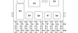
These shortcomings are eliminated by replacing the standard device with an electronic design. In this case, the turn signal relay is connected according to the standard diagram shown in the figure. Pin No. 1 is positive, the second pin connects to the turn switch, the third connects to the warning light, and the fourth connects to ground.
All connections and contacts must be reliably insulated using electrical tape and cambric, which is a hollow plastic braid. This eliminates possible short circuits with other conductors. Certain inconveniences are created by the plastic housing of the electronic relay, which does not always fit in its standard location. However, home craftsmen quite easily overcome this difficulty and find the most optimal technical solution.
Types and location of installation of turn relays in various VAZ models
There are two main types of turn relays used in VAZ cars:
- Classic electromagnetic-thermal relays;
- Modern electronic relays.
The operation of these relays is based on various physical principles, which will be discussed in more detail below. Here we will talk about the applicability and installation features of different types of relays.
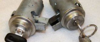
Electromagnetic-thermal turn relays were installed on early VAZ “Classic” models: 2101, 2102 and 2103. Several models of this type of relay were produced and are still being produced; today the RS series relays are most used: RS491M, RS491B, RS57, RS950 and others. These relays are often called “barrel” due to their external design.
Electronic relays began to be installed on VAZ cars, starting with model 2104, and today all current Lada models are equipped with this type of relay. Quite a few models of electronic relays are produced, the most widely used are turn relays 23.3747, 231.3747, 494.3747, 6422.3747 (all installed on models 2104 - 2107), 26.3747, 49.3777, 491.3747, 495.3747 and 712.3777 (all installed on models 2108 – 2110), 07.4747 ( installed on models 2108 – 2115), 14.3747 (installed on the entire line of VAZ “Classic”, VAZ-1111 “Oka”, VAZ-2121 “Niva” and other cars), etc.
Also today, electronic turn relays are produced for VAZ-2101 - 2103 cars, which can be installed without modifications instead of the standard electromagnetic-thermal ones. The most widely used relay is type 71.3777, however, Kopeyki can also use some of the relay models described above.
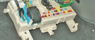
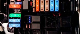
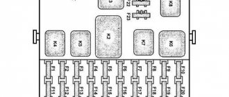
The installation location of the turn signal relay depends on the car model. So, on Zhiguli 2101 - 2106 the relay is mounted directly under the front instrument panel (the ignition relay is also installed there in some models), so it is well protected, and its clicks are clearly audible in any conditions. In later models, the turn relay “migrated” to the relay and fuse mounting block. You need to know the location of the relay, as this can greatly facilitate its replacement in the event of a breakdown.
DIY turn relay
Sometimes situations arise when the standard turn signal relay fails and it is not possible to purchase a new device. In such a situation, you can try to make a turn signal relay with your own hands to provide the car with the necessary signals. The simplest electronic devices that you can create yourself are simple and easy to use, operate smoothly and reliably. High accuracy is achieved through the use of PWM controllers used in all circuits.
The simplest replacement for an electromagnetic relay is designed for a maximum load power of 150 W. It is connected to the positive terminal. If the IRFZ44 field switch is replaced with the IRF3205 model, then 200 W can be connected. This simple circuit ensures high accuracy of operation. The blinking frequency does not depend on the power of the light bulbs, so LED, halogen and other lamps can be included in the circuit.
The frequency of flashing is directly related to the capacitance of the capacitor. As the capacity increases, the light bulb will blink more rarely, and, conversely, decreasing the capacity will lead to faster blinking. The low-power 1n4148 diode can be replaced by any similar element. When the circuit reaches a power of 80 W, a slight generation of heat is observed in the field-effect transistor area. This means it is ready to use.
There is another simple circuit of a turn relay with a coil - simple, reliable and inexpensive. It is capable of lighting both regular light bulbs and LED ones and is designed for 12 V. The contacts are connected according to the principle of a regular switch, that is, in series with the light bulb. The LED is installed in the circuit as an indicator during commissioning work. The device parameters are adjusted by changing the resistance of the resistor.
What to do if the emergency lights stop working
Optics play an important role when driving a car - any malfunction of the lights can create an emergency situation on the road. Turning lights are no exception, they are used both to indicate the direction of turn and for emergency lighting. It is about turn signals that we will talk today in this article, and to be more precise, about their malfunctions.
The design of turning lights is quite simple - wires are connected to the lamps through a fuse and a relay. The relay is turned on by the hazard warning button or the steering column switch. As a rule, a separate relay is installed for each direction of rotation, and a separate one for the emergency lights. Symptoms of malfunction vary in each individual case.
Turn signals don't work
The most common cause of turn signal failure is failure of the lamps themselves. In this case, the resistance of the circuit decreases, as a result of which the frequency of operation of the relay is sharply reduced - this can be noticed immediately after the lamp fails. What to do if this happens while driving:
- Find a place to stop so as not to interfere with traffic
- Turn on the turn signal and see which of the three lamps has failed
- Unscrew the light bulb and check the integrity of the filament
- Replace the lamp if necessary. The lamps are sold in every store and are universal for almost all cars - be it a VAZ or a foreign car.
If the entire turning side does not work, then you need to look for a fault among the fuses, relays and wiring. If you are not at all versed in electrics, we recommend learning the basics by looking at articles, photos and videos about using a multimeter.
Emergency lights don't work
The main reason for the malfunction of the emergency lights is the failure of the relays and fuses. Sometimes this also happens due to poor-quality installation of the alarm system, since its operation is tied to these lights (in some cases, the “signal light” is connected to the side lights).
The failure of the hazard warning lights is not as critical as the failure of the turning lights. However, if the car malfunctions at night on unlit roads, the emergency lights will greatly protect the situation.
The algorithm of actions in the event of a malfunction of the hazard warning lights is the same as with turn signals, except that the bulbs need not be checked - simultaneous failure of all 6 bulbs is not possible.
(1 ratings)Loading…
Source: https://olade.ru/chto-delat-esli-perestala-rabotat-avarijka