Signs of sensor malfunction
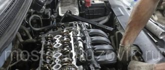
Before you repair the device, you need to find out where the idle speed sensor is located. It all depends on the specifics of the vehicle, but as a rule, this controller is located on the throttle assembly, under the throttle position control. If the location of the DXX is clear, then you can find it without any problems.
Before checking the idle air control, familiarize yourself with the main faults specific to the part:
- the power unit has become less stable at idle;
- engine speed may increase or decrease for no reason;
- when switching to neutral speed, the engine may simply stall;
- if the power unit starts cold, there will be no increased speed;
- when an additional load in the form of a stove, air conditioner or optics is turned on, the engine speed drops significantly.
Idle speed sensor device
We remove the sensor ourselves
1. It is necessary to unscrew the clamps securing the air duct and remove the valve cover ventilation pipes.
2. Then we dismantle the air duct.
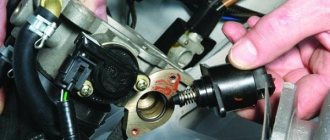
3. Remove the connectors from the throttle position sensor and the idle speed sensor stepper motor
4. Using the head “13” you need to unscrew the nut securing the wire clamp, and with the head “8” unscrew the two bolts securing the idle speed sensor engine.
5. Take out the stepper motor and unscrew the three screws.
6. We proceed to disassemble it and diagnose the malfunction.
After eliminating the malfunction, install the sensor in the reverse order. If you are installing a new sensor, measure the distance between the end of the cone needle and the mounting flange before installing it. It should not exceed 23 mm.
This is necessary so that the regulator needle does not rest against the throttle assembly seat and is not damaged. Clean the valve seat before installation, also clean the air channel and the surface under the sealing ring of the idle speed sensor. Lubricate the ring itself with engine oil. Tighten the fastening screws to a torque of 3–4 N.m.
Posts 1 page 8 of 8
Share112.01.2014 21:20
- Author: Mega-ZZZ
- Mega neon guide
- From: coast of the Black Sea Tuapse
- Gender: Male
- Age: 32 [1987-05-11]
- Posts: 2179
- Respect: +564
- Car: Neon, Stratus
- Year of manufacture: 2000, 2003
- Gearbox type: TH-31 TE-41
- Last visit: 11/24/2018 23:40
- Registered: 11/21/2010
- Spent on the forum: 1 month 8 days
Hello again everyone! Once again we touched on the topic of the ’96 Dodge Neon car. Today we will talk about the idle air regulator for the first neon, the actual essence of the device’s operation is very primitive - by extending and retracting the pin, the air supply to the intake manifold is regulated.
Basically, the regulator cannot be repaired and should not be disassembled.
I’ll say right away - banal spraying in the area of the pin itself does not help lubricant get inside the sensor and does not plan to..
The reason I decided to get to the bottom of the sensor is that nonnon behaves very strangely. I'll post a video later.
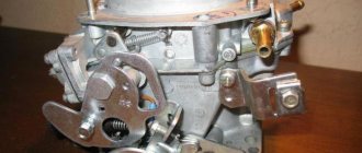
actually let's go. looks great from the outside :)
We take a drill and drill holes next to the rivets so as not to damage them, we will still need them!!
we get a kind of reusable corner latch-groove :)
a couple of hammer blows and that's the happiness that's inside.
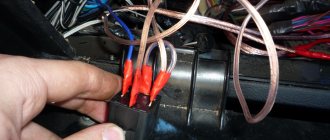
no matter how scary it is, we bite off the wires
Now you can disassemble the valve
here are his insides
here are the windings of 2 of them, the resistance of both of them was 52 ohms!
here is the rotor itself - here it is a magnet with permanent poles, inside of which there is a thread along which the rod rides.
This interesting little thing fell out of him - maybe it was she who was wedging him.
and I also noticed that it clearly jams when it rotates, I lubricated it with silicone and assembled it in the reverse order
The main thing is not to forget to solder the wiring and everything is great - you can go into battle.
I drilled a hole into the groove and screwed in a screw from some Chinese crap - it holds perfectly and is now not difficult to disassemble.
Then all that remains is to check the windings and everything is great, tomorrow I’ll install it and check it :) by the way, now I’m shooting a video, once I edit it I’ll post it, look how I am as a commentator :)))
Edited by Mega-ZZZ (01/12/2014 21:23)
Share212.01.2014 22:01
- Author: dimmaster
- Veteran neon guide
- From: Moscow
- Gender: Male
- Posts: 954
- Respect: +16
- ICQ: 451717023
- Car: Neon
- Year of manufacture: 2002
- Transmission type: automatic transmission
- Last visit: 10/05/2016 20:15
- Registered: 02/24/2012
- Time spent on the forum: 27 days 10 hours
What was the problem?
Share312.01.2014 22:26
- Author: Mega-ZZZ
- Mega neon guide
- From: coast of the Black Sea Tuapse
- Gender: Male
- Age: 32 [1987-05-11]
- Posts: 2179
- Respect: +564
- Car: Neon, Stratus
- Year of manufacture: 2000, 2003
- Gearbox type: TH-31 TE-41
- Last visit: 11/24/2018 23:40
- Registered: 11/21/2010
- Spent on the forum: 1 month 8 days
it feels like it’s jamming, the revolutions should gradually gradually decrease when warming up, but ours is 1200, then something tries, buzzes, and oops - 600 at once, then it almost stalled, they picked up the gas, it picked up again, then again everything worked as it should - then the car sits at idle and warms up, for no reason at all there is a sharp dip again and suddenly it picks up when everything warms up clearly, because the idle speed is no longer particularly regulated when the engine is warmed up.
I decided that there was something wrong with the IAC,
PS the problem with idle appeared gradually, first in the form of unnoticeable stupidities, then obvious failures in operation..
FakeHeader
Comments 33
Really very informative. However, I’ll add my two cents, I also had the same problem, I was itching to disassemble the XX regulator, I’m thinking about how to get this rod out of there. And he went all the way as the author. Only in my regulator the pins easily pulled out like duckbills (later I appreciated this, since I had to open it more than once). Then, when I saw 4 wires under the cover and that’s basically it, I got upset and started surfing the Internet about the internal structure of the engine. And this helped me a lot. The white cap inside covers the bearing, which is held on the magnetic rotor by a retaining ring. After removing the retaining ring, you can wash and lubricate the bearing and twist the rotor from the rod and disassemble the entire mechanism. You can also wash the inside of the rotor, etc. However, for those who climb inside, I’ll immediately warn you that in my Siemens regulator, the thin short wires immediately came off the lid. And it was hardly possible to make out any other way. Then there was a terrible hemorrhoid of servicing and extending these wiring, filling the joint with sealant, turning the cover 180 degrees, since the place with the sealant did not allow the terminals on the cover to fit there. I forgot to change the polarity when I unrolled the cover and this caused the car to idle at 2500 rpm. Overall, the day turned out to be fabulous. Yes, IMHO it is better to use a special lubricant for metal-plastic friction pairs. I used Liqui Moly Thermoflex Spezialfett.
Cleaning Rules
It often happens that cleaning the idle speed sensor can solve the problem of device inoperability. In general, this procedure is quite simple. Therefore, almost anyone can cope with it.
So, how to clean the idle air regulator:
- First of all, the IAC must be disconnected from the wiring.
- Next, take the WD-40 liquid and apply it to a Q-tip. This stick is used to clean contacts.
- Next, take a small Phillips head screwdriver and unscrew the controller latches, there are two of them. If the fastenings are completely missing, this indicates that the IAC is mounted on varnish; if this is the case, then, most likely, the entire throttle will need to be dismantled.
- Dismantle the DXX and inspect it. If there is dirt or traces of motor fluid on the device, then in addition to the regulator itself, you will need to clean the entire throttle assembly.
- Now take a cleaning fluid (you can use carburetor cleaner instead of WD-40) and apply it to the cone needle and spring. Although carburetor cleaner is better for cleaning! Having done this, you need to dry the controller and put it in place. Before installation, make sure that the distance from the device body to the needle is 2.3 cm. If cleaning does not help fix the problem, then most likely you will have to change the DHC.
Controller connection diagram
How to check the idle air control - accessories
Checking the idle air control valve is not a complicated process, so doing it yourself will not be difficult. We can offer at least two approaches, for the first you will need a special device - a multimeter. First, turn off the ignition and disconnect the harness from the IAC. After this, the resistance on all windings of the regulator is checked using a multimeter.
The resistance should be as follows: between windings C and B, as well as A and D - open circuit, and between C and D, A and B - 40-80 Ohms.
You can also make a device for checking resistance yourself, using a 6 V AC transformer. We check the IAC strokes, alternately using switches. A bright light indicates that the idle air control valve needs to be cleaned. For this procedure, you only need carburetor cleaner and WD-40.
Reasons for failure of the idle speed sensor
The incorrect operation of the IAC can be judged by the following criteria:
- No or unstable idle speed.
- Turning off the engine while the vehicle is moving at neutral speed.
- When warming up in cold weather, the engine speed does not rise to 1500.
- Also, when you turn on electrical appliances, a drop in speed is possible, but this may also indicate a malfunction in the vehicle’s electrical network.
The most common reason for the failure of the idle speed sensor is oil from the boat exhaust system, in other words, from the breather. When this liquid gets on the sensor needle, coking occurs due to the fact that the throttle mechanism is constantly heated by the water system.
This happens quite quickly and noticeable idle problems appear more and more often, directly depending on the condition of the piston system. In some cases, if the engine is heavily worn, it is recommended to disconnect the breather from the air system and seal the inlet before repairing it. This will not only help avoid frequent cleaning of the idle air regulator, but will also help save fuel consumption, because in addition to oil particles entering the air channel, carbon dioxide escapes from the crankcase, which prevents complete combustion of the fuel.
Another common cause of rough idle is a poorly sealed air system. Most often, the auxiliary pipes on the adsorber and the fuel pressure regulator are damaged; the corrugation in the area of the mass flow sensor (mass fuel flow sensor), which is installed on the air filter cover, may burst.
These faults can only be corrected by replacement. As a rule, when the air channels are damaged, an uneven idle is observed with a characteristic hissing under the hood or when the speed is constantly raised.
If the car has covered a lot of kilometers, more than 50,000, then it is advisable to wash the entire throttle assembly, and based on the results, proceed directly to replacing the idle speed unit itself.
How to determine that the idle air control regulator needs repair?
Malfunctions of the idle speed control are quite easy to detect; in this case, the “CHECK ENGINE” lamp will definitely light up on the instrument panel . This can happen for a number of reasons, the simplest of which is a wire break, however, most often, the cause may be the wear and tear of the cone needle drive or its guides. As for the symptoms indicating that the idle air control valve urgently needs repair, they will be as follows:
- when the gear is engaged, the engine stops working;
- The engine speed during idling is quite unstable, perhaps even an involuntary decrease or increase, sometimes vibration;
- when starting a cold engine, there will be no increased speed;
- As soon as the additional load is turned on, the speed decreases immediately.
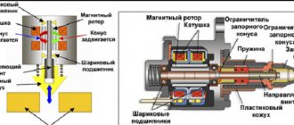
Purpose, device and principle of operation
The main components of the idle air control sensor include a cone needle, a stepper motor, a spring and a rod. You can see the insides of the pxx in the image below.
The conical needle is used to change the throughput of the regulator. which affects the amount of air supplied to the engine. The spring is used to create counteraction and eliminate backlash in the operation of the sensor. The stepper motor acts as a drive. Control signals are generated in the ECU, taking into account information from other sensors, for example, the position of the crankshaft or coolant temperature.
The principle of operation of the device is based on changing the cross-section of the air flow channel going into the combustion chamber when the throttle is locked. The stepper motor extends the rod until the tapered needle touches the hole. When you start the machine, the PHH opens the passage, supplying the required amount of air. For a better understanding of the principle of operation of the idle air regulator, you should pay attention to the cross-section of the idle air control shown below.
The operation of the regulator allows for accelerated warming up of the car. When the coolant sensor signals that the engine is operating below the permissible temperature range, the amount of air supplied automatically increases. As a result, the crankshaft speed increases and heating occurs more intensely. Thanks to the pxx injector, you can drive the car immediately after starting the engine, which is not available to owners of carburetor engines.
The pxx is located near the throttle sensor. The stepper motor cover stands out strongly against the background of the assembly. The difficulty of finding where the regulator is located only arises if it is located under a common plastic casing that protects the devices from mechanical damage.
Eliminating floating idle speed for Renault Logan
Even beginners can handle troubleshooting such problems, so we’ll look at the repair steps in detail:
- To gain access to the throttle assembly, remove the air filter housing. On Reno Logan car engines, it is fastened with both M8 bolts with a 10mm head and Torx 20 or Torx 30 head screws. You will see two mounting points right in front of you. Remove one screw on the left and right of the air filter (on the side of the engine compartment shield).
- After unscrewing the fasteners and rocking the air filter housing to the sides, pull it out of place. It will not be possible to completely dismantle the part due to the breather, which is connected to the pipe on its lower plane. Since the breather hose is not secured in this place with clamps, to remove it, lift the air filter on the right side (in the direction of travel) and with a sharp movement pull the hose off the pipe. After this, set the air filter aside.
- Using a screwdriver or finger, press the spring latch of the throttle position sensor connector to disconnect it from the terminal block.
- Remove the idle air control sensor connector.
- Disconnect the throttle linkage. To do this, pry it up with a flat-head screwdriver and remove it from the ball joint.
- The engine throttle valve is held by a shaped plate, which is secured with a Torx 30 screw. There is no need to unscrew it completely - release it a little, after which the clamp moves to the side and is disconnected.
- To remove the throttle, pull it up. Without a mounting plate, the assembly is held in place solely by the O-rings installed at the bottom of the housing.
- After removing the throttle assembly, carefully inspect the condition of its components. Carbon deposits and soot on the inner surface of the diffuser are indirect evidence of contamination of the idle air regulator.
- The next step is to remove the idle air control (IAC) from the throttle valve. This device is attached to the throttle body with two self-tapping screws with cutouts for a Torx 20 bit. After unscrewing the screws, pull the IAC out of the socket. You will have to apply a little force - the regulator is installed with minimal interference.
- After dismantling the idle speed control, do not disassemble it by force under any circumstances. The fact is that this device has a rather delicate design and therefore requires a special approach.
- First of all, turn on the ignition and remove the negative terminal of the battery. After this, connect the IAC connector, and, holding the device in your hand, connect the terminal to the battery for a few seconds. At this time, the idle air control rod will move out of its socket. Sometimes the device becomes so overgrown with carbon deposits that it is impossible to disassemble it the first time. In this case, repeat the power supply procedure, maintaining a 5-second pause between turns on.
- After disassembling the IAC, clean the housing from dirt and remove deposits in the internal cavity. To do this, the channel of the device is filled with diesel fuel or kerosene, a rod of a suitable diameter is inserted into the hole and the IAC housing is rotated in one direction or the other. Having restored the performance of the bearings, the liquid is drained. The needle valve seat is cleaned of diesel fuel with a jet of WD-40 and blown out with compressed air.
- Next, clean the stem and valve plate (cone) of the idle air control. Car enthusiasts who are involved in minor repairs more than once know that such work is best done with a used toothbrush. Stiff bristles moistened with kerosene or solarium wash away any dirt. After cleaning, the part is doused with “Vedashka” or “Carbcleaner” and dried in a stream of compressed air. The bushing of the adjusting unit is also cleaned in the same way.
- Before you begin assembling the IAC, apply grease to its rod. There are no special requirements for this material - the main thing is that it does not freeze in the cold. Good results were shown by the “blue” lubricant VNIINP-246, well known among car enthusiasts, which operates in the temperature range from -80 °C to 200 °C.
- Assemble the idle speed control. To do this, a sleeve with a spring is installed in its body, after which a conical needle is inserted. Do not force the rod inside the IAC. This detail will take its place after the so-called training, which we will talk about a little later.
- Putting the assembled regulator aside, begin maintenance of the throttle assembly. Thoroughly clean all its internal cavities, including the diffuser, throttle valve, seat and seat of the IAC valve.
- Let's start training the IAC. After removing the rubber ring from its body, install the device on the throttle assembly. Press the regulator against the mating plane exactly as much as the length of the cone needle allows - while there may be a gap between it and the throttle body. Next, connect the connector to the IAC and repeat the procedure described in paragraph 10 several times. After repeated power supply, the valve cone will take the optimal position.
- Next, return the rubber ring to its place and fasten the regulator, orienting its connector towards the manifold.
- If during dismantling the throttle was removed without effort, this indicates wear of the rubber rings. To eliminate the possibility of air leaks, replace them.
- We install the throttle assembly on the engine.
- The body of the throttling device is fixed with a shaped plate, and then the PPX connector and the throttle position sensor block are connected.
- Inspect the accelerator cable and check how easily it moves in the sheath. Any damage (broken wires or deformation of the sheath) is a reason to replace the part with minimal effort. In any case, lubricate the cable with machine oil.
- Attach the throttle linkage and connect the negative terminal to the battery - it’s time to do a test run.
Most often, engine idling is restored after the first engine start. If the malfunction cannot be eliminated, then the cause of the floating speed of the power unit should be looked for elsewhere. This could be a breakdown of the electrical part of the IAC, a faulty throttle position sensor or a failed mass air flow sensor, air leaks into the intake manifold and other, more specific faults.
Currently reading: Assembling the rear brake mechanism Renault Logan 1 |
Something else useful for you:
Main aspects of checking IAC
We figured out how to clean the idle speed sensor, now we’ll take the time to diagnose it. Like cleaning, testing can be done at home.
How to check the idle speed sensor:
- Find the IAC and remove it along with the wires. Unscrew several clamps that secure the throttle assembly with the receiver, then move these elements apart by about 1 cm.
- Using a diagnostic tester, check the IAC circuit - now you should make sure whether there is voltage in the network or not. Connect the tester probes to contacts A and D - as a rule, they are marked on the body. Having connected the probes, you need to activate the ignition and look at the results. The best option is 12 volts. If this parameter is lower, then most likely the problem lies in a poor battery charge, and if it is completely absent, then it is quite possible that the problem lies in the control unit.
- Make sure that the circuit is on the IAC itself. To do this, the tester's probes must be connected to pins A and B, and then to C and D, and you need to set the tester to ohmmeter mode. When checked, the diagnostic parameters should be about 53 ohms. Then the same actions should be repeated with other pairs of contacts, for example A and C, and the resistance should tend to infinity (the author of the video is Ivan Vasilyevich).
There is another option; for this, checking the idle speed sensor must be carried out with the IAC removed. Connect the power cable, then touch the end of the needle with your finger (no force required). During shutdown, the regulator should begin to extend the needle fully, so when you turn, there should be a slight push of the finger.
As you can see, in general, diagnosing a device is not that difficult, but for a quality test you need to understand how to use the tester. If you have no idea how to do this, it is better to seek help from an electrician, but in practice, after studying the instructions for the multimeter, there should be no problems with its use. Of course, the tester itself must be working, otherwise the readings will not correspond to reality and you will only get confused.
Sorry, there are no surveys available at this time.
Lada 2114 Cast iron speedboat › Logbook › Checking and repairing the idle air control
Alexander Kudrin, 59 years old I drive a Lada 2114 Cast iron outrider Chelyabinsk, Russia
Good day! The other day the car engine suddenly stopped holding idle speed. The engine began to stall at every traffic light, as well as when coasting and sometimes when changing gears. If I kept the gas pedal slightly pressed, the engine did not stall. Moving around the city has become uncomfortable and somewhat dangerous. I immediately thought about the idle air control (IAC). However, there was no time to do it, but I had to go. To maintain idle speed when the IAC is not working, you need to open the throttle valve slightly, for example, using a stop screw. However, I didn’t want to change the factory setting of the damper position. Fortunately, we have a lot of all kinds of rubbish lying along the sides of the roads, including useful ones. Having pulled off the road and walked around the car, I found a piece of galvanized steel, from which I cut out a strip using universal scissors from the driver’s tool kit, and then bent it into a “squiggle”.
Tools and objects of labor found on the side of the road
Squiggle made of galvanized steel
I put this “squiggle” on the damper lever, ensuring its guaranteed opening by about 2 mm. The engine stopped stalling, running steadily with the gas pedal released at a rotation speed of 1000...1100 rpm.
Installing a Fabricated Part on the Throttle Lever
Two days later I had some free time and I decided to do IAC. In order to remove it, I had to unscrew the nuts of the throttle assembly and move it forward by 10...15 mm. Otherwise, there was no way to unscrew the lower IAC fastening screw.
Regulator XX on engine 11183. To remove it, I had to unscrew the throttle assembly
The removed IAC appeared to be intact and not even dirty. Of course, it could be replaced with a new one, but this is not our way. I decided to find out what exactly is the reason for its inoperability.
Idle speed control
The windings of the stepper motor rang: both had the same resistance of 52 Ohms and did not short to each other. Therefore, the cause is mechanical damage. I didn’t know how to disassemble the IAC, so I went straight ahead, pulling out and drilling out the mounting pins for the rear cover of the IAC. Having pressed it with a screwdriver, I realized that I had done the disassembly in vain: I didn’t see anything useful there except the compound that filled the windings and the four wires going from the connector to these windings. Therefore, if the windings are ringing and are not broken, I do not recommend opening the back cover. I put everything back together and thought about a way to remove the valve from the inside of the stepper motor. After reading the literature and scouring the Internet, I learned that this valve cannot be removed simply. It is necessary to force the rotor of the stepper motor to rotate and then the valve, which has a screw thread on the rod, will begin to move along the IAC axis. With each change in the polarity of the current on one of the windings of the IAC motor, the rotor will rotate one step, moving the rod by a small fraction of a millimeter. Therefore, in order to extend the rod, it is necessary to transfer the wires for quite a long time on the output contacts of the current source or on the IAC contacts. To speed up and ensure the convenience of performing this procedure, I made a simple probe based on the KM2-1 double button.
Subtleties of purchasing a new IAC
After purchasing a new regulator, you need to configure it. The injector calibrates itself using the computer, so there will be no difficulties with how to change the sensor. To perform the operation automatically, it is enough to de-energize the injector before installing the IAC.
When purchasing a new regulator, you should pay attention to its quality. The valve and other elements must not have any defects or deformations. The quality of contact soldering must be at a high level. Installation on the seat must occur without distortions, otherwise repairs will soon be required.
The air flow passing through the valve solved the issue of engine operation without load. Now the throttle valve is entrusted with the function of controlling dynamic characteristics, and at idle speed the engine is in full control of the rxx. The ability of the sensor to increase speed allows the car owner not to waste time waiting for the engine to warm up.
What are the signs of its malfunction?
While such sensors are not yet equipped with diagnostic systems, the driver will not see a signal on the display about its malfunction. For now, it is possible to judge the problems with it or check the RkhnaVAZ 2114 only by indirect signs, which are quite sufficient to make a correct diagnosis. These signs include:
- Unexpected stops when idling;
- Floating speeds are observed when operating at idle speed;
- It is impossible to achieve an increase in speed when starting a cold engine;
- When the speed is turned off, the motor stops.
I would like to warn car owners that similar signs of malfunctions occur in other sensors, but the controller reacts to some of them and displays an error code on the display.
Currently reading: Replacing the rear brake cylinder of Renault Logan: instructions
Features of dismantling
As for dismantling the controller, there is nothing difficult about it. Of course, some points may vary depending on the design features of your vehicle.
But in general the withdrawal procedure looks like this:
- First, the ignition is completely turned off. Just in case, to prevent a short circuit, you can disconnect the negative terminal from the battery.
- The next step is to disconnect the regulator's power wiring. Typically this connector is a four-pin output and can simply be disconnected. On some cars, the wiring block can be fixed using an additional fastener - there is nothing complicated here, you just need to disconnect the fastener.
- After this, the regulator mounting bolts are unscrewed and the controller itself is removed.
Cleaning procedure
To clean the element, the first step is to remove it. Disassembly of the spare part begins with removing the air duct corrugation and disconnecting the wires from the idle air control regulator and the part position sensor. The dismantling procedure does not require any special effort.
Note! When dismantling the throttle valve, it is important that the power unit is not hot. Because there is a risk of getting burns.
Then you should remove the hoses that are connected to the spare part, and then the cable from the drive. Thus, the path to the damper is open. Simply unscrew a couple of nuts and bolts and remove the position sensor and idle air control.
Cleaning consists of washing the element. To do this, it is recommended to use a special product designed for cleaning carburetors. The substance should be sprayed onto all surfaces and channels. Upon completion of the process, the part should be wiped with a rag.
We recommend: “Kurgan trailers” - quality at a reasonable price
Special attention should be paid to the idle air control. Due to excessive contamination, the needle may jam and not work properly. And before installing elements, you should check the general condition of this element. If the needle has a large free play, the part must be replaced.
It is also necessary to assess the condition of the gasket before installation. If damage is present, the element should be replaced.
Note! After completing the installation of the throttle valve, the cable tension should be adjusted.
When do you need to clean the Lacetti throttle body?
If, during computer diagnostics, it is revealed that the throttle valve on a warm engine in xx mode does not close by more than 5%, then this unit requires mandatory cleaning.
The damper must also be cleaned if there is heavy visual contamination. This will affect not only the smooth operation of the engine, but also fuel consumption.
How to clean the Lacetti throttle body?
Many people clean the throttle assembly without removing it from the engine. This is not entirely correct, since contamination remains from the inside and, especially on the damper axis! Therefore, it is better to remove the damper. Moreover, I do it in 10 minutes.
- Removing the decorative trim of the engine
2. Loosen the two clamps on the corrugation
Loosen two clamps on corrugation
3. Use pliers to loosen the clamp and remove the crankcase ventilation hose from the valve
Remove the crankcase ventilation hose from the valve
4. We dismantle the corrugation along with the crankcase ventilation hose and this is what we get:
We dismantle the corrugation along with the hose
5. Pressing the latch from below, disconnect the wire block from the Chevrolet Lacetti throttle assembly
Disconnect the wiring block from the throttle assembly of the Chevrolet Lacetti
6. Turn the throttle drive pulley clockwise and remove the accelerator pedal cable through the groove.
Removing the drive cable from the Lacetti throttle assembly
7.Now many people disconnect the coolant supply hoses to the throttle body, but I don’t do that. First of all, it's faster. Secondly, there is no need to be tricky with plugging the hoses to prevent coolant from flowing. Thirdly, air will not get into the cooling system.
I simply remove the hoses from the holders and they are long enough to remove the throttle assembly.
8. Unscrew the three nuts and bolt securing the Chevrolet Lacetti throttle assembly and remove it from the studs
Unscrew the three nuts and bolt securing the Chevrolet Lacetti throttle assembly
As you can see, there is not a lot of pollution, but there is still
Lacetti throttle valve dirty
9. We place a rag under the throttle assembly so as not to smear the engine and wash off the dirt from the cylinder
Cleaning the Lacetti throttle body
10. It is advisable to replace the gasket, clean the end of the intake manifold and the DDA fitting, the adsorber and the crankcase ventilation
Lacetti throttle body gasket
11. It is advisable to immediately flush the Lacetti crankcase ventilation valve. To do this, we unscrew it...
Crankcase ventilation valve Lacetti
...and wash it so that the spring works without jamming
Flushing the Lacetti crankcase ventilation valve
We also wash the corrugation with the tube
This is the result that makes me happy
Clean throttle body of Chevrolet Lacetti
12. Putting everything back together in reverse order.
Here is a video on how to clean the throttle body
How to clean the throttle valve?
Nowadays, the choice of means for this procedure is simply huge. Everyone will find something more suitable for their needs and financial capabilities.
For example, I use this tool
Throttle Body Cleaner
It costs us 3-4 USD. It washes everything quickly and efficiently, which suits me.
The instructions say that you can even flush the fuel system by pouring it into a tank of gasoline. It also cleans the intake tract.
Throttle body cleaner
After cleaning the throttle body, the Lacetti's revolutions fluctuate
After cleaning the throttle body, the throttle position adaptation must be reset.
This can be done through a special adapter and the Chevrolet Explorer program. Or at the service station.
You can see in this short video what happens and how when resetting adaptations with the throttle valve
Peace to your home and good luck on your journey!
Installing the sensor in reverse order
Once the sensor and its seat are completely cleaned, complete assembly can begin. To do this, it is important to lubricate the rubber sealing ring with grease or unused oil and carefully install it in its normal place without damaging the integrity of the seal, without which operation of the vehicle will be impossible.
The work is done, now everyone knows perfectly well how to clean the idle air valve. It is safe to continue driving your vehicle.
Sensor diagnostics
You can check the idle air valve yourself. Its faults can be divided into two parts: mechanical and electrical. There are several verification methods.
Visual inspection
First you need to conduct a visual inspection. In this way, you can detect body defects, needle wear, and carbon deposits. If deposits form, you can clean them with carburetor cleaner. It is also recommended to clean the entire throttle body as it is in a similar condition.
Using diagnostic programs
The operation of the IAC can be checked using a diagnostic adapter and special programs. For example, you can use the simplest ELM327 adapter and the OpenDiagMobile program. In the program menu you need to select the desired position of the XX regulator and watch the operation of the valve. It is better to set it at least 20 steps more than the current position.
Wiring check
For this we need a multimeter. With the engine off, remove the connector from the sensor. We set the measurement limit on the measuring device to 0-20 V DC voltage. We measure the voltage at the connector. Normally it should be 12V.
Checking the regulator resistance
To do this, we will need to measure the resistance between terminals A, B, and C and D after disconnecting the sensor terminal. We move the multimeter to the position of measuring resistance at the limit of 0-200 Ohms (Ω).
The normal value is within 50-55 Ohms. The resistance between A and C, B and D must be infinity.
Checking with throttle assembly
There is another way to diagnose IAC. To do this, you will need to remove the throttle assembly from the studs along with the sensor.
By connecting the valve connector and turning the ignition on/off, you can observe the operation of the IAC live. See how the needle works, if it is rubbing somewhere, check the evenness of the stroke, hear suspicious sounds.
After cleaning the throttle body the speed fluctuates
So, it would seem that the whole procedure is over. The damper was cleaned with a cleaner, the air filter was replaced with a new one, the sensors were reconnected, that is, everything was assembled and tightened. Now you can proceed to starting the engine. If the engine starts after cleaning the throttle valve and then runs normally, then the procedure can be considered successful.
It should be added that this is not always the case. Many people are faced with the fact that after cleaning the throttle valve, high engine speeds remain constant and do not drop. Also, many drivers notice that after cleaning the throttle valve, fuel consumption has increased. A likely cause could be an error in connecting some sensor during reassembly, but this rarely happens.
Most often, after cleaning, the throttle also needs to be additionally calibrated and adjusted, which not everyone knows about or does it incorrectly. In other words, high idle speeds after cleaning the throttle valve are a clear example and at the same time an answer to the common question of whether the throttle valve needs to be trained after cleaning this unit. Let's figure it out.
We recommend: How to choose the right engine oil?
Let's start with the fact that in some cases a pure throttle valve really needs to be adapted (trained). Typically, throttle valve adaptation is often necessary when the electronic throttle valve has been cleaned before. There are fewer problems with a mechanical damper, but they still exist. In systems with an electronic throttle, the ECU independently sets the throttle position; in mechanical systems, the idle air control is set. To put it simply, after removing the layer of dirt, the position of the cleaned damper changes, but the ECU does not know about this and continues to supply fuel in accordance with the previous parameters before cleaning. To solve the problem, it is necessary to set the idle speed using diagnostic equipment, since it is possible to reset the previous parameters.
You can also try teaching the throttle manually. The simplest way to learn without diagnostic equipment or a scanner for adaptation is to unscrew the negative terminal of the battery from a few seconds to 10 minutes (depending on the make and model of the car). This allows you to reset the settings, that is, the existing adaptation is reset and returned to the factory settings. After connecting the terminal to the battery and restarting the engine, the idle speed should stabilize.
Note that this method works on a limited number of cars. In such a case, you can take advantage of another opportunity to train the throttle assembly without a computer. This method is suitable for a range of vehicles from different manufacturers. Let's consider such an adaptation using the example of a Japanese Nissan car.
- First, the engine must be warmed up to operating temperature, after which the engine should be turned off.
- Next, you will need to wait 5-10 seconds, then turn on the ignition for 3 seconds.
- Now you need to press the gas pedal all the way and immediately release it. This is done 5 times, you need to do it in 5 seconds (one press per second). The interval should be timed using a stopwatch so as not to get lost.
- After the last press, you should wait 7 seconds, after which the gas pedal is again pressed “to the floor” and held in this position until the “check” begins to blink on the dashboard, and then this light comes on constantly.
- After the moment when the check code starts to light up constantly, you need to wait another 3 seconds. Now the gas pedal can be released.
- Next, the engine needs to be started, the idle speed should return to normal.
Let us add that during such adaptation of the throttle valve it is important to accurately maintain the timing at each stage, as well as to fit into all time intervals. In this case, we can talk about successful training. It is also recommended to clarify the features and the possibility of manual adaptation for a specific car model.
Resetting adaptations without adapter
It would seem that everything is clear - you need to take the adapter, laptop and reset the adaptations. But not with us. We are not used to doing things the right way. We want to reinvent the wheel on any issue.
Therefore, in the vastness of the network, cherished algorithms called “Resetting adaptations without a cable” or “How to simply reset adaptations”, or “The secret method of resetting adaptations” are passed on from generation to generation.
The procedure generally looks like this:
1. turn on the ignition for 5 seconds 2. turn off the ignition for 10 seconds 3. turn on the ignition for 5 seconds 4. start the engine in neutral (manual transmission) or Park (automatic transmission) 5. warm up to 85 degrees (without accelerating). 6. turn on the air conditioning for 10 seconds (if equipped) 7. turn off the air conditioning for 10 seconds (if equipped) 8. for automatic transmission: use the parking brake. Press the brake pedal and put the automatic transmission in position D (drive) 9. turn on the air conditioning for 10 seconds (if equipped) 10. turn off the air conditioning for 10 seconds (if equipped) 11. turn off the ignition.
By the way, this procedure was presented on our website in a post describing the Lacetti ECU. And this procedure serves to train the ECU, and not to reset adaptations!
Therefore, it turns out that we are trying to train a full bucket of beer so that it can hold another 10 liters
For reference, here is an excerpt from the Chevrolet manual:
Procedure for determining idle speed parameters
- Turn on the ignition.
- Reset the adaptation values with the scan tool. (Only with main throttle valve idle speed control drive)
- Turn off the ignition for 15 seconds.
- Turn on the ignition for 5 seconds.
- Turn off the ignition for 15 seconds. (For Siemens D160 ECM with ETC system, turn off the ignition for 35 seconds.)
- Start the engine in park/neutral.
- If the vehicle is equipped with an automatic transmission, apply the parking brake. Depress the brake pedal, shift the gearbox to position D (driving) for 1 second and return it back to position P (parking). (Siemes ECM only).
- Run the engine until the coolant temperature rises above 85°C (185°F).
- Turn on the air conditioner for 10 seconds, if available.
- If the vehicle is equipped with an automatic transmission, apply the parking brake. Depress the brake pedal and set the gearbox to position D (drive) for 10 seconds.
- Turn off the air conditioner for 10 seconds, if equipped.
- If the car is equipped with an automatic transmission, depress the brake pedal and shift the transmission to the parking/neutral position.
- Turn off the ignition. The procedure for determining the idle speed parameters is completed.
- Wait 15 seconds before starting the engine again (Siemens ECM only). (For Siemens D160 ECM with ETC system, turn off the ignition for 35 seconds.)
Did you notice point #2? I think now there will be no questions left.
For the process to be successful on all cars, the adaptations must be reset only forcibly through the K-line. No amount of shamanism or disconnecting the battery will force the ECU to delete adaptations from non-volatile memory. Some firmware, of course, may have some tricks of their own.
Well, now let’s directly look at the procedure for resetting ECU adaptations