Usually the fact that the VAZ 2107 has a voltage regulator is remembered when a problem arises with charging the battery. To be completely precise in the definitions, the voltage relay comes to mind immediately as soon as it turns out that, despite the presence of charging, the battery is almost completely discharged. Let's take a closer look at why a voltage regulator is needed in a VAZ 2107 car.
Without going into the intricacies of electronics, the voltage regulator is designed to regulate the voltage at the generator output depending on the operating mode of the engine. It is quite natural that as the speed changes, the voltage level also changes. And if it drops to 12 volts or lower, the battery stops charging.
Therefore, if you suspect a malfunction in the VAZ 2107 charging system, you must first check the voltage at the battery terminals. This can be done using a regular voltmeter or multimeter (tester). In normal mode, the voltage should be approximately 13-14 volts. If it falls below 13, you should pay attention to the relay; it may need to be replaced.
Depending on the type of generator used in the car, the regulator can be internal three-level and external. The internal one is built into the generator and is usually used in VAZ 2105 and 2107 cars, while the external one is used in earlier classic models and is located in the engine compartment on the left arch.
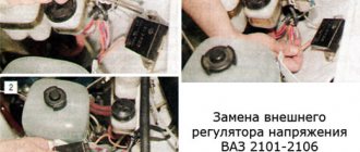
Depending on the type of regulator, replacing it has its own characteristics. Replacing the external regulator is no problem. Using a size 8 wrench, unscrew the two fastening nuts and disconnect the wires from terminals 15 and 67. The new relay is installed in the reverse order. After checking that the wires are connected correctly to the terminals of the regulator, and that its body is in reliable contact with ground, you can start the engine and measure the voltage again to ensure that the fault has been eliminated.
The internal three-level one is somewhat more difficult to change due to limited access to the generator. But, despite this, the task is quite doable even without removing it. Replacing the regulator, as in the case of an external one, comes down to disconnecting the wires and unscrewing two mounting screws using a Phillips screwdriver. After this, the relay is removed from the generator housing. Installing a new regulator occurs in the reverse order. After assembly, the voltage level is checked.
It should be noted that the regulator is not always replaced due to its failure. Recently, more and more often, car enthusiasts have resorted to replacing the generator along with the relay from an old model to a new one. This kind of tuning becomes possible thanks to the complete interchangeability of both models. The reason that prompts car owners to take such a step is the high efficiency that distinguishes the three-level regulator from the standard one.
Repair of voltage regulator relay on VAZ 2107
Usually the fact that the VAZ 2107 has a voltage regulator is remembered when a problem arises with charging the battery.
To be completely precise in the definitions, the voltage relay comes to mind immediately as soon as it turns out that, despite the presence of charging, the battery is almost completely discharged. Let's take a closer look at why a voltage regulator is needed in a VAZ 2107 car. Without going into the intricacies of electronics, the voltage regulator is designed to regulate the voltage at the generator output depending on the engine operating mode. It is quite natural that as the speed changes, the voltage level also changes. And if it drops to 12 volts or lower, the battery stops charging.
Therefore, if you suspect a malfunction in the VAZ 2107 charging system, you must first check the voltage at the battery terminals. This can be done using a regular voltmeter or multimeter (tester). In normal mode, the voltage should be approximately 13-14 volts. If it falls below 13, you should pay attention to the relay; it may need to be replaced.
Depending on the type of generator used in the car, the regulator can be internal three-level and external. The internal one is built into the generator and is usually used in VAZ 2105 and 2107 cars, while the external one is used in earlier classic models and is located in the engine compartment on the left arch.
Depending on the type of regulator, replacing it has its own characteristics. Replacing the external regulator is no problem. Using a size 8 wrench, unscrew the two fastening nuts and disconnect the wires from terminals 15 and 67. The new relay is installed in the reverse order. After checking that the wires are connected correctly to the terminals of the regulator, and that its body is in reliable contact with ground, you can start the engine and measure the voltage again to ensure that the fault has been eliminated.
The internal three-level one is somewhat more difficult to change due to limited access to the generator. But, despite this, the task is quite doable even without removing it. Replacing the regulator, as in the case of an external one, comes down to disconnecting the wires and unscrewing two mounting screws using a Phillips screwdriver. After this, the relay is removed from the generator housing. Installing a new regulator occurs in the reverse order. After assembly, the voltage level is checked.
It should be noted that the regulator is not always replaced due to its failure. Recently, more and more often, car enthusiasts have resorted to replacing the generator along with the relay from an old model to a new one. This kind of tuning becomes possible thanks to the complete interchangeability of both models. The reason that prompts car owners to take such a step is the high efficiency that distinguishes the three-level regulator from the standard one.
New type relays provide the required voltage level in automatic mode. Plus, it has a wider adjustment range than the standard one, so the battery receives an optimal charge. Under such conditions, the service life of the battery is significantly increased. In the schematic diagram of the electrical circuits of the VAZ 2107 shown below, the relay is indicated by the number 7.
Diagnostics
To check the installed relay, simply measure the voltage at the battery terminals, and it will become clear what condition it is in. To check what has been removed and is suspicious, the verification method is slightly different, but in any case it will help to identify:
- Absence or poor contact in the brush holder terminals.
- Broken brush conductors.
- The relay itself is faulty.
A multimeter or a 12-volt test lamp, the power of which does not exceed 2 W, is simply connected to the regulator brushes. It is enough to apply 10-12 V, the lamp should light up or the multimeter should show the corresponding value. After this, a voltage greater than the nominal voltage is supplied - 16-20 volts. In this case, the relay should operate, but the lamp should not light. If the lamp continues to light when the voltage increases, then the regulator is broken and does not perform its functions. In this case, it must be replaced. Also, when replacing, you should pay attention to the condition of the brushes. They should protrude beyond the brush holder by no more than 5 mm.
This way you can test your regulator and save the battery from premature wear. Keep an eye on the network voltage, and have a good trip!
The principle of operation and malfunctions of the VAZ-2107 charging relay
In the article we will talk about what a charging relay on a VAZ-2107 is and what functions it performs. And most importantly, we will understand the operating principle of various types of devices. This element is inconspicuous, very reliable and inexpensive, but it can fail at the most unexpected moment. As a rule, drivers pay attention to it after the battery loses charge. This leads to a lot of other problems - the engine does not start, electrical equipment does not work correctly. To prevent this from happening, you need to check the functionality of the charging relay.
Checking the functionality of the device
To carry out diagnostics, you will need a voltmeter (you can even use a simple incandescent lamp), as well as a constant voltage source with regulation of 12.20 V.
To carry out diagnostics you need to perform the following manipulations:
- The negative terminal of the power source must be connected to terminal “Ш” (or the housing of the voltage regulator).
- To the terminal marked with the letter “B”, connect the plus from the power source.
- Connect a voltmeter or incandescent lamp to the brushes.
If the charging relay is working properly, then at a voltage of 12.14 V the control lamp will light up. When the voltage increases/decreases, the lamp should go out. If this does not happen, you can judge that the voltage regulator is broken.
Please note that the brushes must protrude from the housing by at least 5 mm. If they are very worn, replace them.
What does it look like and where is it installed?
Now let's find out where the VAZ-2107 charging relay (carburetor) is located. Initially, this device was placed away from the generator on the arch under the hood (on the left side). On newer “sevens” equipped with an injection system, the voltage regulator was combined with a brush assembly.
The first voltage regulators were based on electromagnetic relays; they worked quite slowly and required constant intervention. The problem is that mechanical elements wear out very quickly. In addition, it was constantly necessary to adjust the gaps in the relay. Modern semiconductor devices operate silently, quickly, without electromagnetic relays. One silicon crystal can perform the functions of several mechanical relays.
Checking the functionality of the device
To carry out diagnostics, you will need a voltmeter (you can even use a simple incandescent lamp), as well as a constant voltage source with regulation of 12.20 V.
To carry out diagnostics you need to perform the following manipulations:
- The negative terminal of the power source must be connected to terminal “Ш” (or the housing of the voltage regulator).
- To the terminal marked with the letter “B”, connect the plus from the power source.
- Connect a voltmeter or incandescent lamp to the brushes.
If the charging relay is working properly, then at a voltage of 12.14 V the control lamp will light up. When the voltage increases/decreases, the lamp should go out. If this does not happen, you can judge that the voltage regulator is broken.
Please note that the brushes must protrude from the housing by at least 5 mm. If they are very worn, replace them.
Replacing fuses for VAZ 2107
The fuse box table describes the positions and names of fuses that perform a specific function for each section of the circuit or group of circuits.
If a fuse link fails or a section of the circuit fails, you can find and check the condition and serviceability of the required fuse. To do this you should:
- Open the cover on the power supply and find the serial number of the required protection element.
- If damage to the fuse is not visible visually, then you should remove the fuse link from the board socket and “ring” it with a multimeter, measuring its resistance. This operation should be performed with the vehicle's power turned off and it is additionally required to disconnect the battery terminal.
- A failed fuse should be replaced with a similar one corresponding to the specified current value on the insert body or the rated current of the circuit.
- Removing the fuse from the board socket and replacing it with a new one from the group of reserve inserts located in the block is done using tweezers attached to the block body. In the absence of tweezers, work is performed with small pliers.
Malfunctions
The first symptom of a generator malfunction is the appearance of the following errors on the on-board panel:
- P0560 indicates insufficient electrical voltage in the circuit. Direct notification of insufficient current from the generator. The first reason may be: weakening of the transmission belt, poor contact at the generator terminals.
- P0561 is a low circuit voltage alert. In addition, the battery charge indicator lamp lights up during operation of the power unit. Accurately indicates a problem with the generator itself.
- P0562 indicates that the electrical voltage in the circuit is too high. The reason lies in the relay regulator. The device did not include high current protection at the generator output.
The appearance of errors requires the owner to check the generator for faults. They may be the following:
- Very low tension on the belt that transmits rotation from the power unit.
- Belt slipping on the generator or engine pulley. May cause wear on pulley surfaces.
- Break, short circuit and complete burnout of the excitation coil.
- Insufficient brush contact.
- Incorrect operation of the charge relay.
- Failure of the diode bridge.
- There is a short circuit in the circuit.
- Poor contact.
To accurately identify the cause of the malfunction, it is necessary to check each element of the circuit and the charge supply device to the battery one by one.
Why is a charging relay needed?
To maintain the correct charging mode of the battery, as well as to ensure the normal functioning of all electrical appliances in the vehicle’s on-board network, the generator must produce a voltage in the range of 13.6 ... 14.6 V. Under load, the generator must produce about 14 V stably. Using a regulator, the voltage changes in the power circuit of the rotor winding.
The essence of the generator's operation is that as the supply voltage to the excitation winding increases, the voltage at the generator output increases. It is the voltage in the rotor winding power circuit that stabilizes the regulator. If this is not done, the voltage supplied to the winding will change (it depends on the speed, load on the engine crankshaft, etc.).
When starting the engine
As soon as the engine is started, the following processes occur:
- Core magnetization.
- The spring force is overcome, and the group of contacts K1 opens.
- The first stage of regulation is turned on.
- Electric current is supplied to the inductor and additional resistances (R ext = 5.5 Ohms).
- The current in the rotor winding gradually increases, and the voltage decreases.
- Contact group K1 closes.
The process is repeated again, the armature vibrates and constantly closes and opens the contacts. Voltage is sometimes supplied to the excitation winding, sometimes not. When the rotor rotates very quickly, a small resistance is switched on in its winding circuit - as a result of this, the voltage increases to a maximum of 14.6 Volts. The current in the winding increases to such a value that the second group of contacts K2 is attracted. At the same time, the second stage of voltage regulation is activated.
Fuse and relay diagram for VAZ 2107 old model. Video
The old-style fuse and relay box includes 17 fuses mounted on the board using spring contacts and 6 electromagnetic relays.
The block has two printed circuit boards mounted parallel to each other and connected by jumpers. It is also connected to the car’s network through detachable connections made in different colors for proper docking. The photo below shows a diagram of the location of power supply control elements and VAZ 2107 relays.
Photo of old VAZ 2107 fuse box
The body is made of plastic; there is a cover on top with the location of the elements on the block and their purpose in the form of images. The table below shows the decoding and pinout with the assignment of fuses and relays of the VAZ 2107 car.
What to do if the battery on a VAZ 2107 (injector) does not charge?
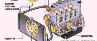
There are two energy sources in a car. Battery and generator. Moreover, the generator is the main one, since it is able to charge the battery while driving. In the most extreme, desperate cases, battery energy can be used. According to various estimates, in the most optimistic case, you can drive about 100 km on a flat road on a battery. In this case, the headlights should not be turned on, the heater should not be turned off, and, preferably, the ambient temperature should be low and the speed should be constant so that the radiator fan does not turn on. And the battery will be fully charged. Only in this case all the energy will go into the “spark”.
If the VAZ 2107 engine (injector) is running and there is no battery charge, there may be many reasons.
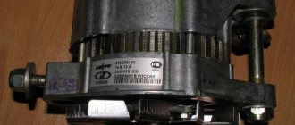
Let's start with the generator. The VAZ 2107 (carburetor) has an alternating current generator (model 372.3701), and an alternating current rectifier is built into the design. This is a synchronous three-phase motor.
The reasons why the battery is not charging can be common, regardless of whether you have a carburetor or an injector. Let's consider the reasons when the generator is to blame, that is, there is no voltage at its terminals. This can happen because the rectifier bridges (diode), the winding and many other reasons have burned out.
The VAZ 2107 (injector) is equipped with a figure-eight generator 5142.3771. Its difference from a conventional generator on a VAZ 2107 is that it produces a higher current, not 55 A, but about 80-90 A per hour, since the injector requires more electricity, it is more modern and has a higher power density. The figure shows a generator producing a rectified current of 80 A at a voltage of 14 V.
Attention! Before claiming that charging has disappeared specifically in the VAZ 2107 generator, check:
- If there is incoming voltage at the generator, this does not yet prove that it is the generator that is damaged and there is no outgoing current. After all, diodes supply current to the excitation winding of the generator. In this case, the battery charge lamp will light up on the dashboard.
- It is also worth measuring the voltage in the network with a tester. If it is below 12 V, then most likely there is a short circuit somewhere, and in this case the wiring may heat up intensely.
- You should check the generator belt, or rather, its tension. If it is loosely tensioned, then instead of driving the generator rotor, the belt slides along it itself, since there is no contact.
- The generator charging relay has failed. We need to talk about this separately.
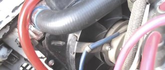
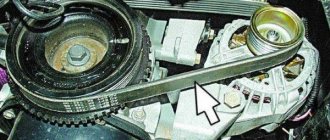
The charging relay on the VAZ 2107 (injector) is located in the same housing with the brush mechanism, and its task is to stabilize the output voltage. Several years ago there were relays that were stamped into a printed circuit board and were located under the instrument panel and were non-separable. In the figure, the relay is indicated by an arrow. In everyday life, due to its characteristic shape, it is called a “tablet”.
Now, with the development of microelectronics, the printed circuit board is successfully replaced by a semiconductor relay. The sizes have become smaller, and there are no problems with installation.
Generator brushes - why are they needed?
Quite often (especially in older models) there are cases when, with a sharp increase in driving speed, various seemingly inexplicable things happen: the light of the dashboard or headlights dims, the cigarette lighter and (or) radio work intermittently. Drivers who have not been hardened by many years of experience in the cold lake may mistakenly think about burnt fuses, wiring, or shorted devices. It can take a whole day or more to work through all these versions. But what will be the driver’s surprise when the true cause of the malfunction becomes clear, that the whole essence of the problem is due to some small pieces of black metal called generator brushes.
Based on 9th or 8th grade physics lessons, everyone knows that any generator must include two main parts, one of which is movable (rotor), and the second, correspondingly, stationary (stator). Each part has a copper (in most cases) winding. Under the influence of magnetic force, the rotor begins to rotate, powered by electricity through the armature and two other metal parts. And they are called generator brushes. Due to the constant impact of friction, all parts gradually wear out due to the constant rotation of the rotor. This happens in any case, regardless of the quality of the material of the parts (and it is really strong).
How to determine the malfunction?
If, while warming up the car, you begin to notice strange actions on the dashboard (the voltmeter readings change greatly with minimal engine load or the battery charging light comes on), then this can only mean one thing - the alternator brushes are worn out and need to be replaced.
In some cases, a good warm-up of the engine allows you to “extinguish” the indicator. At the same time, the car drives on the autobahn quite calmly and normally, without any signs of malfunction. But you shouldn’t be such an optimist, because your car may break down at the most inopportune time. Don't forget to check the condition of the alternator winding and belt, although the absence of sparks and smoke suggests that the brushes are the cause of the breakdown.
When is it time to change generator brushes?
The main signs of brush failure on a generator:
Methods for replacing brushes
Unit repair is carried out using 2 methods:
The method for restoring the unit depends on the layout of the units in the engine compartment and the condition of the threaded connections. If there is a coating of rust and oxides on the steel elements, it is recommended to remove the electrical machine.
The parts are treated with a special liquid, otherwise the edges of the nuts will be licked off or the body of the bolt will break.
Before replacing the brushes on the generator, you need to prepare:
On a removed generator
Algorithm for servicing a unit using the example of a VAZ-2113 car with an 8-valve power unit:
Removing the alternator on other vehicles may require removing the air filter housing or air ducts. On some foreign-made machines, automatic tensioning devices are used; the body of the electrical device is rigidly bolted to the cylinder block.
The owner needs to loosen the belt tension and then remove it from the pulley. On Toyota vehicles, the electrical components are covered by a metal casing secured with nuts.
Under the cover there is a brush block, a diode bridge and a charging control unit (equipped with an aluminum radiator). After removing the brushes, the collector rings are inspected; if there is wear on the parts, you will need to remove the rotor to correct the defect. After assembly and installation, the voltage in the on-board network is checked with the engine turned off and running.
What reasons can cause the charging relay to fail?
Only two, not counting severe damage to the generator housing:
- “planned” wear of brushes, which are graphite electrodes. In this case, the contact is gradually broken and disappears completely. As a result, no current is supplied to the excitation winding of the generator, and it does not work;
- A short circuit has occurred in the electrical circuit itself, while there is an output current on the generator and battery, but it is higher than 14.8 V.
The charging relay is located on the generator, on its back cover, and, no matter what shape and color the “tablet” is, a yellow wire comes out of the generator body to it. The relay is located so that it can be replaced without removing the generator. But for convenience, the pictures show work on a removed generator.
How to replace the charging relay?
- Important! First, as always, we turn off the ground, remove the negative wire from the battery terminal, then remove the yellow wire going from the generator to the relay, then use a Phillips screwdriver to unscrew it;
- Then we take it out together with the brushes:
- Now we need to carry out diagnostics. To do this, we test the voltage on the brushes with a voltmeter, and we power the relay itself from the battery, “simulating” the rectified current of the generator. At the same time, we apply (+) to terminal “B”, to the yellow wire, and connect (-) to the other terminal, “ground”. We are familiar with the signs of trouble. If you don’t have a tester, you can take a 1-3 W, 12 V light bulb.
- When installing a new relay, you need to press it firmly during installation, since new, unworn brushes provide more resistance.
If after taking these measures there is no effect, you need to look for the cause in the generator, we’ll talk about this next time. At the same time, remember that if you are removing a generator, then either you have decent knowledge in electrical engineering, or you have someone to give it to. There is no third option, especially if you have an injector.
In conclusion, let me tell you about several other reasons for the lack of charging or imitation, and also give advice:
- If you have a VAZ 2107 injector, then it is strictly not recommended to reset the battery terminal for various “checks” while the engine is running, and especially to allow strangers near the hood for this purpose. This is very harmful to electronic “brains”.
- It is advisable for those who like to “light up” to be able to say a firm “no” if you have a VAZ 2107 injector.
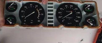
- On the instrument panel, the connectors are not soldered to the board, but riveted. Therefore, in some cars in the cold, while the interior is cold, there is no contact with the charging lamp. It lights up, simulating a lack of current from the generator. After the interior has warmed up, contact is restored and the lamp goes out.
- The next reason for those who like to go to the car wash in the cold. When water gets into the relay and brush assembly and freezes there, there is no charging. The solution is to heat it with any powerful hairdryer.
Purpose of the voltage regulator
The purpose of the voltage regulator is easy to guess from the name of this device. The regulator's task is to maintain the current coming from the generator at such a level that the voltage generated by the same generator is always kept within specified limits.
Moreover, it should not depend on the rotation speed of the generator. And the current consumed by the car should also not affect the voltage created by the car generator. The generator voltage regulator is responsible for performing all these tasks on a VAZ 2107 car.
Types and location of voltage regulators
As you know, the VAZ 2107 car began to be produced a very long time ago. And over the years, not only different motors were installed on it, but also different voltage regulators. On the earliest models, the relay regulators were external. On later “sevens” the regulators were internal three-level. Let's take a closer look at these devices.
External voltage regulator VAZ 2107
It is the external voltage regulator that many motorists in the old fashioned way call a “relay-regulator”. Today, external voltage regulators can only be seen on very old “Sevens” produced before 1995. These cars were equipped with an old generator model 37.3701, which was equipped with external relays.
The external regulator was located under the hood of the car; it was mounted on the left front wheel arch of the car. As a rule, external relays were made on the basis of a single semiconductor, although after 1998 on some VAZ 2107 there were external regulators made on a common printed circuit board.
External relays had certain advantages:
- Replacing the external regulator was fairly easy. It was held on by only two bolts, which were not difficult to reach. The only mistake that a beginner could make when replacing this device is to mix up terminals 15 and 67 (they are located next to each other on the regulator);
- the cost of the external regulator was quite affordable, and they were sold in almost all car stores.
Of course, the device also had disadvantages:
- bulky design. Compared to later electronic regulators, the external relay seems very large and takes up too much engine compartment space;
- low reliability. External VAZ regulators have never been of high quality. It is difficult to say what is causing this: the low quality of individual components or the poor build quality of the device itself. But the fact remains a fact.
Internal three-level voltage regulator
Internal three-level voltage regulators began to be installed on the VAZ 2107 starting in 1999.
These compact electronic devices were built directly into car generators.
This technical solution had its advantages:
- compact sizes. Semiconductors were replaced by electronics, so now the voltage regulator fits in the palm of your hand;
- reliability. It’s simple: there’s nothing special about electronic devices that breaks. The only reason why a three-level regulator could burn out is a short circuit in the on-board network.
There are also disadvantages:
- difficulty of replacement. If there were no particular problems with external regulators, then to replace the internal relay the car owner first needs to get to the generator. To do this, he will have to remove the air filter and a couple of air ducts, which requires patience and time;
- difficulty of acquisition. As you know, the VAZ 2107 has long been out of production. So getting new components for the “seven” is becoming more and more difficult every year. Of course, this rule does not apply to all details. But internal three-level voltage regulators for the VAZ 2107 are among the parts that are not so easy to find today.
Purpose and principle of operation
Injection models VAZ-2107 are equipped with a generator type 37.3701. This device is superior in power to carburetor model generators.
Model 37.3701 amperage ranges from 80 to 90 amperes. This power is necessary for uninterrupted power supply to the entire electrical circuit, plus an additional load is provided. Unlike the carburetor model, the generator has to power a large number of sensors, the engine control unit, and a more powerful ignition module. The electrical circuit of an injection car includes a larger number of consumers.
A car generator is not much different from conventional stationary ones. It works on the principle of converting rotational energy into alternating electric current. Rotation is carried out by a transmission belt from the engine. The principle is as follows:
- After turning on the ignition, a current of 12 volts is supplied to the generator.
- This circuit includes a battery charge indicator lamp, which is installed on the dashboard. The lamp lights up after turning on the ignition.
- As soon as the power unit starts working, the generator stator begins to rotate due to the belt, converting the magnetic field into electrical voltage.
- AC voltage passes through the diode bridge.
- The bridge converts alternating voltage to direct voltage.
- Electrical voltage is transmitted from the diode bridge to the brushes and the adjustment unit.
- The difference between the charging current and the battery voltage causes the warning lamp to go out.
During operation, the generator of the injection VAZ-2107 produces from 13.5 to 14.3 volts of voltage. This is enough to charge the battery and maintain the operation of all consumers.
Next, a description of the main generator malfunctions will be given.
Dismantling and checking voltage regulators on a VAZ 2107
First, let's decide on the tools and devices that will be needed for the job. Here they are:
- household multimeter;
- open-end wrench 10;
- flat screwdriver;
- Phillips screwdriver.
Sequence of work
If the driver suspects that the voltage regulator is broken, then the first thing he should do is check the voltage supplied by the battery.
- The car engine turns off and the hood opens. Using a multimeter, the voltage between the battery terminals is measured. If it drops below 13 volts (or, conversely, rises above 14 volts), then this indicates a breakdown of the regulator.
Video: checking the voltage regulator on a VAZ 2107
Like any other device, the voltage regulator can break down suddenly. And it’s especially difficult for the driver if the breakdown occurs far from home. There is nothing surprising here: drivers who constantly carry spare regulators with them need to look further. But even in such a difficult situation, there is still a way to get home (or to the nearest service center). But you won’t be able to get there quickly, because every hour you’ll have to crawl under the hood and remove the terminals from the voltage regulator. And then, using a suitable piece of insulated wire, connect the positive terminal of the battery and contact “Ш” on the regulator. This is done so that the charging current does not exceed 25 amperes. After this, the regulator terminals return to their place, and the car starts. You can drive it for about 30 minutes, and you should turn on the maximum number of energy consumers - from the headlights to the radio. And after 30 minutes you should stop again and do the entire above procedure again, since without this the battery will simply recharge and boil.
So, even a novice car enthusiast can check the voltage regulator on a VAZ 2107. All that is required is the ability to use a multimeter and a screwdriver. Following the recommendations listed above will allow the car owner to save about 500 rubles. This is how much it costs at a car service center to check and replace the voltage regulator.
0 0 votes
Article rating
Examination
You can check the functionality of the generator without dismantling it. Before checking, the following steps must be taken:
- Disconnect the terminals from the battery, clean them, replace them and tighten them tightly.
- Clean terminal “30” of the generator. Check the wire of this terminal for damage to the insulation and repair any defects.
- Check belt tension. It is better to install a new belt to avoid slipping on the pulleys.
Particular attention is paid to the ground terminal. It must be disconnected and the area of attraction must be cleaned with sandpaper. The terminal, bolt and washer are also cleaned.
Next you need to check the battery charge level. To do this, you will need a multimeter in voltmeter mode to measure DC voltage. The charge of a working battery varies from 11 to 12.5 volts. Next you need:
- Start the power unit.
- Check the voltage on the battery while the generator is running.
- If the voltage gradually drops, this indicates a complete absence of incoming charging current.
- A voltage above 14.5 volts will indicate a high charge current, which can lead to boiling of the battery.
If the charging current is sufficient, varying within 14.5 volts, then while the power unit is operating, you need to turn on the car’s lighting and repeat the measurement. A powerful generator should not respond to the connection of new consumers by reducing the charge current. If this happens, then the mechanism should be tested after preliminary dismantling.
The following will describe how to check the generator during operation. To check you need:
- Set the multimeter to DC current measurement mode.
- Connect the red test probe to terminal “30” of the charging mechanism.
- Connect the black test probe to ground.
- A working generator should produce at least 14.3 volts DC. If there is no voltage, then you need to switch the multimeter to AC measurement mode. The results that appear will indicate a breakdown of the diode bridge.
Further checks of the alternator will require removing the unit from the vehicle. This requires:
- Loosen the tension bolt.
- Move the generator towards the engine.
- Remove the transmission belt from the pulleys.
- Unscrew the fastening bolt.
- Dismantle the generator, first disconnecting all wires.
Next you need to disassemble the device. The following items can be checked with a multimeter: rotor, stator, charging relay, brushes, diode bridge and capacitor. The following will describe how each element is checked.
Rotor
The generator rotor is based on a copper inductor. It is hidden under metal protection. All these elements are mounted on the shaft. To check you need:
- The multimeter is switched to resistance measurement mode.
- The red dipstick connects to the first ring on the shaft.
- The black dipstick connects to the second ring on the shaft.
Both rings are located directly behind the outer bearing. The operating resistance of the coil should be no more than 5 ohms. If there is no resistance, then the part is considered unsuitable for use. High resistance will indicate a short circuit. The verification procedure is as follows:
- The multimeter is switched to dialing mode.
- The tester's red probe connects to the first slip ring.
- The black probe connects to the rotor housing.
The buzzer will indicate a breakdown of the coil winding on the housing. If there is no buzzer, then ring 2 must be checked. The test is performed in the same way. If the test does not reveal any malfunctions, then it is necessary to clean off the resulting oxidation, dirt and rust from the surface of the body. It is also worth checking the condition of the bearings. Elements with large play must be replaced.
The stator rings play an important role. It is necessary to clean them from dirt, oxidation and adhering graphite particles. The surface of the rings must be perfectly flat, without wear along the edges or in the middle. Any distortions must be straightened out. This is done only on the machine. When processing, it must be taken into account that the minimum permissible thickness of the rings is 12.8 mm. Below this level, there will be insufficient contact between the brushes and the rings. This will lead to interruptions in the charging current for the battery.
Diode bridge
The design of the diode bridge of the VAZ-2107 car includes 6 diodes. They are assembled according to a 3x3 pattern. To check, you must first disconnect the bridge from the generator circuit. Next you need:
- Switch the tester to diode testing mode.
- Connect the red probe of the tester to the anode of the first diode of the circuit, this is the contact side of the element.
- Connect the black measuring probe to the aluminum plate.
- The absence of a sound signal will indicate a breakdown of the first diode. Then you need to ring all 3 elements. The call is carried out every other time.