ISO pinout or pinout is the identification of each electrical connection pin in a connector or diagram according to its corresponding numbering and functionality. The speaker system of any manufacturer is connected to the standard ISO connectors of the car. Proper pinout will help you get a good sound at the output and not burn out the connectors with voltage. You can understand the wires using standard diagrams. You can install any brand of car radio without having specialized knowledge in electrical engineering. When working with non-standard connectors, do not forget about safety. “Ring” the wires using a multimeter.
What is iso
ISO is an international organization that develops standards and regulations for various industries. The abbreviation sounds the same in all languages. A Russian manufacturer working in accordance with standards labels its products with the abbreviation “ISO” or “ISO”. All well-known developers of car radios equip their products with two types of standard plugs. Each looks like an eight-pin rectangular connector.
Backlight fault
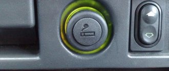
Often, especially in CD/MP3 devices from the middle price segment, problems are observed with the backlight.
Note. Almost always, the interference manifests itself as follows: the characters are somehow displayed on the display, but at the same time the backlight affects the buttons and the rotary.
The principle of screen illumination in head units of recent years of production is as follows: monitors and indicators themselves are not capable of emitting a beam or shining, and for demonstration they require illumination from the side - as a rule, these are white LEDs.
The problem in this case may be caused by the LEDs not producing light due to current problems. Specifically, either the limiting resistor or the LEDs themselves are damaged.
If you have knowledge of fixing equipment yourself, I can advise you where to find suitable replacement light bulbs. There may be a damaged mobile phone lying around somewhere at home (of a modern type), in which instead of a flash there are just such LEDs. All that remains is to pick them out from there.
Answered by: Denis Kustov, site expert
Denis dreamed of going to live abroad, so he devoted all his free time not to cars, but to foreign languages.
After graduating from the St. Petersburg University of Foreign Languages and passing IELTS (International English Language Exam), Denis left for America. After two years of living in the United States, Denis returned to his homeland. However, in America, Denis had a lot of friends who pumped cars, and in two years the level of knowledge of the intricacies of acoustics was not inferior to the level of knowledge of foreign languages. At the moment, Denis wants to open his own car service in St. Petersburg, in which he will pump up your car no worse than in the American program “Pimp My Cars.” Add a comment
Do not answer
Pinout of a standard Euro connector
A Euro connector is a standard plug used in most countries around the world. When connecting equipment, you may encounter non-standard wires tangled in a bundle. This problem is solved by purchasing adapters and pinouting the radio chips.
Standards 1din and 2din
Speaker system connectors come in two types: non-standard ones from the manufacturer, mostly pin-type, and standardized European ones, which are located at the back. Installation of equipment with a special audio connector from the manufacturer will require the use of a special proprietary connector. If the plug is ISO, then you can connect to it directly. There are two types of Euro connectors: 1din and 2din, the difference is in the height of the car radios. The two-block one is twice as tall; it is not connected to all cars, because there is no space on the panel for the required dimensions.
Radios with European 1din are the most common.
When installing car radios, wires with a small diameter of 1.5-2 mm are used, for power lines - with a large cross-section. Failure to follow these simple rules will distort the sound and damage the equipment.
| № 1 | — |
| № 2 | — |
| № 3 | — |
| № 4 | Constant power |
| № 5 | Antenna power |
| № 6 | Backlight |
| № 7 | Ignition |
| № 8 | Weight |
Manufacturers in Japan, the USA and some Chinese use the 2din standard.
Upper power connector A
The plug is used to supply electricity to the receiver, antenna and amplifier, as well as when it is necessary to control the backlight or turn off the sound signal. Standard color markings are used. Outputs 1-3 and 6 are not used in low- and mid-price segment speakers; they are intended for additional options for high-end products.
Connection types
- The first is the connection in the socket of wires of two colors, yellow and red, turning the receiver on/off does not depend on the ignition. The method is inconvenient because it predisposes the battery to discharge if the acoustics are not turned off;
- The second wire is connected through the ignition switch, the yellow wire is connected to the on-board computer.
Functional purpose of the receiver outputs
| ANT | The connector is used if the car has a retractable antenna |
| Remote | Multiple speakers can be connected |
| Illumination | Allows you to change the intensity of the device's glow |
| Mute | Adjusting the sound |
| A4 | Turn on/off |
Pinout of radio ISO connector
| A 4 | Color yellow | Battery + Power |
| A 5 | Color blue | Antenna. |
| A 6 | Color orange | Backlight |
| A 7 | Color red | Ignition, 12V. When disconnected, reset settings to factory settings. |
| A 8 | Color black | Acoustics |
Bottom speaker connector B
Used to connect amplifiers (2 cables each). The sound of the equipment depends on whether all connectors are connected correctly. The main thing is not to confuse them, otherwise the acoustics will be of poor quality.
Rules for connecting speakers by color marking of wires
| Color white | Left front |
| Color grey | Right front |
| Color green | Left rear |
| Color violet | Right rear |
What are the wires used for and where do they go?
Wires for car radios are used to connect to a power source, speakers and amplifier, remove control signals and implement service functions. Thanks to clear identification by color, the likelihood of making a mistake when connecting is reduced, since it is clear which wires go where and what they are needed for.
Orange
The orange wire (ILL) is most often used to control the backlight of the car radio display. It connects to the parking light switch. In this case, several backlight control scenarios are possible. For example, you can make its brightness automatically decrease when the side lights are turned on.
Yellow and red
According to the generally accepted standard, the yellow and red wires are used to connect the positive pole of the power supply to the car radio. Through the first of them, constant power is provided to the device’s microcircuits along with the audio power amplifier and display backlight. When voltage is applied to the yellow cable, all functions of the car radio begin to work. Often, its break is connected to a fuse in a housing that matches the type. The higher the output power of the car radio, the higher the rating of the fuse link.
The red wire, constantly connected directly to the battery, provides continuous power to the volatile memory chip, which stores radio stations recorded by the owner, car radio parameters and the place where listening to music from the media was stopped. The yellow wire is often connected not directly to the on-board network, but through the ignition switch. Thanks to this approach to power supply, the current consumed by the receiver is reduced several times.
Blue and pink
The blue wire is used by some manufacturers to control a motorized antenna. It is supplied with power when the radio mode is turned on. When the radio is turned off, the antenna is automatically retracted, since it contains an additional relay, which is powered directly from the battery. Another purpose of blue is to enable additional functions. For example, the Reverse wire on the radio is used to activate the parking sensors or rear view camera mode.
Pink is used to implement various service functions. One of them is blocking multimedia functions on a 2-din radio with a video player. The control signal is most often supplied from the warning lamp switch under the parking brake lever. As soon as the pink cable is connected to ground, it becomes possible to start the video player or turn on the TV tuner. Otherwise an error message will appear on the display.
Blue - white
The blue-white cable (blue wire with a white stripe) is designed to control the power of the active antenna. It is often marked with a tag marked “Remote”. This cable also supplies a control signal to the car amplifier. The connection can be made either directly to the device or through a special relay.
Dual ISO connector
The standard audio systems of some cars are connected with a double plug. The pinout of connectors for them is standard. The contact halves are connected to each other by a durable plastic jumper and secured with a special clamp. For correct installation, a guide groove is used, which prevents the plug from being installed in the wrong position.
The black one connects a current source to the radio, the brown one for acoustics.
Abbreviations on car radio connectors
The article provides a decoding of the designations of car radio connectors; this may help you when installing the equipment in your car yourself:
Power connector:
1 - B+ or BAT or K30 or Bup+ or B/Up or B-UP or MEM +12 = Battery powered.
2 - GND or GROUND or K31 or simply Minus is indicated = Common wire (Ground).
3 - A+ or ACC or KL 15 or SK or S-kont or SAFE or SWA = Power is supplied from the ignition switch.
4 - N/C or n/c or N/A = No contact. (Physically the output is there but not connected anywhere).
5 - ILL or LAMP or Sun symbol or 15b or Lume or iLLUM or K1.58b = Panel illumination. +12 volts are supplied to the contact when the side lights are turned on. Some radios have two wires, -iLL+ and iLL-. The negative wire is galvanically isolated from ground.
6 — Ant or ANT+ or AutoAnt or P.ANT +12 volts are supplied from this contact to control the retractable antenna (Mercedes) or to the active one for others (not always).
7 - MUTE or Mut or mu or Image of a crossed out speaker or TEL or TEL MUTE = Input to mute the sound when receiving a phone call.
8 - GALA or GAL = Speed sensor input. Automatic adjustment of the sound level (increase) as the vehicle speed increases (a more modern sound compression function is used in PIONEER DEH 945R radio tape recorders; the radio tape recorder has a measuring microphone). Speaker connector: 1 - R = Right speaker. 2 - L = Left speaker. 3 - FR+, FR- or RF+, RF- = Front speaker - right (plus or minus, respectively). 4 - FL+, FL- or LF+, LF- = Front speaker - left (plus or minus, respectively). 5 - RR+, RR- = Rear speaker - right (plus or minus, respectively). 6 - LR+, LR- or RL+, RL- = Rear speaker - left (plus or minus, respectively). 7 - GND SP = Speaker common wire. Other pins: 1 - Amp = External amplifier power-on control pin 2 - DATA IN = Data In 3 - DATA OUT = Data Out 4 - Line Out = Line Out 5 - CL = ??? 6 - REM or REMOTE CONTROL = Control Voltage (Subwoofer, Amplifier) 7 - ACP+, ACP- = Bus Lines (Ford) 8 - CAN-L = CAN Bus Line 9 - CAN-H = CAN Bus Line 10- K-BUS = Bidirectional serial bus (K-line) 11- SHIELD = Connection of shielded wire braid. 12- AUDIO COM or R COM, L COM = Common (ground) input or output of preamplifiers 13- ATX+ = ??? 14- ATX-MUT = ??? 15- CD-IN L+, CD-IN L-, CD-IN R+, CD-IN R- = Symmetrical linear inputs of audio signal from the changer 16- SW+B = Switching power supply +B battery. 17- NAVI = ??? 18- SEC IN = Second input 19- DIMMER = Changing the brightness of the display 20- ALARM = Connecting alarm contacts for the radio to perform car security functions (PIONEER radios) 21- ASC IN and ASC OUT = ??? 22- SDA, SCL, MRQ = Communication buses with the vehicle display. 23- SDV or SDVC = ??? 24- SWC = ??? 25- LINE OUT, LINE IN = Line output and input, respectively. 26- TIS = ??? 27- D2B+, D2B- = Optical audio link
But at this link there is an archive, in the exe archive (shnik), you launch and the pinouts of radio tape recorders from various manufacturers will open, including those coming standard from the factory: https://disk.yandex.ru/public/?hash=rfxZb/RGhG08ztNABX5qOs5nxAthyHllVg3ukidE57s% 3D
Adapters for ISO connectors
Cutting off a non-standard standard plug and connecting the wires directly is not recommended, because over time the connection will become loose, may oxidize, you will have to solder not only the wiring, additional repairs will be required, replacing blown fuses. Sometimes there are acoustics with three outputs, but they have standardized markings and electrical circuits that allow you to connect standard cables to the device using pinouts. You can buy any type of adapter for ISO connectors from one model to another.
The car may not be equipped with connectors, then you need to connect the radio connector to the cable directly. This is done by twisting, soldering, or using a terminal block that does not require subsequent insulation. When twisting and soldering, heat shrink tubing is used for safe use of the equipment.
How to connect a Pioneer radio - methods
It is worth noting that connecting the Pioneer radio can be done using two methods:
- Using a standard ISO connector.
- Connecting a radio without standard connectors.
It is necessary to understand that if you use the second method of installing the radio, the warranty on the device will no longer be valid, and there is a high probability of making a mistake when connecting the wires. However, in many cases there is simply no other way out. For example, this option is the only one if your car does not have the appropriate connector for connecting a radio.
Even if you use an ISO connector, you need to do everything very carefully and first make sure that the wiring of the terminals on this connector is done correctly.
The standard connection diagram for a Pioneer car radio provides for the following wire markings:
- The thick yellow wire is the connection to the car battery. It should be noted that this wire must be connected only through a fuse.
- The red thick wire is connected to the same battery, but through the car’s ignition switch. This is necessary so that the device functions only when the ignition is on. Some car owners prefer to connect the red and yellow wires, but this risks the car battery being discharged at a completely unexpected moment. Due to the use of this method of connecting the Pioneer radio, in case of prolonged parking it will be necessary to disconnect the housing terminal from the battery.
- The thick black wire is the connection to the car body or the negative terminal of the battery.
- The white-blue wire is responsible for powering the active subwoofer, antenna or amplifier. After turning on the radio, 12V voltage appears on the wire.
Connecting a Pioneer radio - speaker wires
- Right front speaker - the gray wire goes to the “plus” of the speaker, and the gray-black wire goes to the “minus”.
- Left front speaker - connect the white wire to the “plus” of the speaker, and the white-black wire to the “minus”.
- Right rear speaker - the purple wire goes to the “+” of the speaker, and the purple-black wire goes to its “-”.
- Left rear speaker - connect the green wire to the “plus” of the speaker, and the green-black wire to the “minus”.
The connection procedure is complete, you just need to connect the battery and enjoy the operation of your new Pioneer radio.
Pioneer radios are today one of the most common and popular audio systems among our compatriots. The products of this brand have been in demand among consumers for many years, thanks to which new models of radio tape recorders are constantly appearing on sale. In this article we will tell you how to connect a Pioneer car radio with your own hands, and what malfunctions are typical for such systems.
User manual
Photo gallery “What you need to know about connection”
Video “What to do if the radio is phoning?”
Comments and Reviews
Pinouts for various brands of cars and radios
Before getting started, read the instructions for the receiver, and also pay attention to the markings and features of the product itself. The pinout of radios is influenced by standard connectors in different cars.
Pinout diagram for ISO connectors for pioneer radios
Connecting the acoustics of this well-known brand, which is popular among motorists, has some features. Be sure to read the installation manual before starting work. Installation is simple, the main thing is to understand the purpose of each color. In addition to the instructions, the kit includes two “chips” with 4 pairs of contacts: for power and acoustics.
The pinout of the plug has 10-20 outputs, the functionality of each connector varies depending on the model. The KEH series is characterized by the following circuit: No. 1 - antenna, No. 2 - ignition, No. 3-6 and 8-11 - amplifiers. To avoid confusion, please read the instructions carefully.
In order not to burn out the acoustics, before connecting the speakers you need to connect the radio, check that it lights up and switches.
toyota
The pinout of acoustics of this brand is carried out according to standard diagrams. It is optimal to choose a power supply system from a battery, in this case there is no risk of its discharge.
ISO connector:
| № 1 | A+ |
| № 2 | GND |
| № 3 | BAT+ |
| № 4 | Backlight |
| № 5 | Antenna |
| № 6 | Speakers (RR+, RR-, RF+, RF-, LF+, LF-, LR+, LR-) |
sony
When connecting the radio, standard circuits are used.
| № 1 | ANT |
| № 3 | L.R. Line output |
| № 4 | GND. Line output |
| № 5 | R.R. Line output |
| № 6 | CD–LCH |
| № 7 | CD - GND |
| № 8 | CD–RCH |
| № 9 | CD - Reset |
| № 10 | CD – CD clock out |
| № 11 | CD – DSPL select |
| № 12 | CD – data out |
| № 13 | CD – clock in |
| № 14 | CD – data in |
| № 16 | A+ |
| № 17 | GND |
| № 18 | ANT GND |
| № 22-27 | Speakers (LF-, LR+, RF-, RR+, LF+, LR-, RF+, RR-) |
| № 28 | Mute |
| № 29-30 | Speakers (LF-, LR+, RF-, RR+, LF+, LR-, RF+, RR-) |
| № 31 | ANT CONT |
| № 32 | CD ACC Constant |
| № 33 | AMP Constant |
| № 34 | BUP |
nissan
Universal connector:
| № 1-6 | Speakers (LR+, RR+, LR-, RR-, LF+, RF+) |
| № 7 | A+ |
| № 8 | Backlight |
| № 9 | BAT+ |
| № 10 | Speakers LF- |
| № 11 | RF speaker |
| № 12 | Antenna |
| № 13 | GND |
honda
All models of car radios are equipped with a universal European plug for connection to the socket.
| № 1 | Speaker RR+ |
| № 2 | Speaker LR+ |
| № 3 | Backlight |
| № 4 | BAT+ |
| № 5 | A+ |
| № 6 | Antenna |
| № 7-10 | Speakers LF+, RF+, RR-, LR- |
| № 13 | GND |
| № 14-15 | Speakers LF-, RF- |
bmw
Standard European pinout.
| № 1 | A+ |
| № 2 | BAT+ |
| № 3 | GND |
| № 4 | — |
| № 5-12 | Speakers RR+, RR-, LF+, LF-, RF+, RF-, LR+, LR- |
alpine
Alpine TDE-7823W: 1 – BAT+,
| № 2-5 | Speakers LR-, LR+, RR-, RR+ |
| № 7 | Amplifier |
| № 8 | Antenna |
| № 9 | GND |
| № 10-13 | Speakers LF-, LF+, RF-, RF+ |
| № 5-12 | A+ |
mitsubishi
All models use standard European speaker pinout.
| № 1-2 | Speakers RR+, LR+ |
| № 3 | Antenna control |
| № 4 | Backlight control |
| № 5-8 | Speakers LF+, RF+, RR-, LR- |
| № 10 | A+ |
| № 11 | BAT+ |
| № 12 | Backlight control |
| № 13-14 | Speakers LF-, RF- |
| GND |
Post navigation
Connecting speakers This procedure is carried out carefully and carefully, since not only the purity of the sound depends on this, but also the operation and durability of the radio and speakers. MUTE Responsible for muting the sound when the button is pressed.
Sometimes there are two of them, and they control the operation of devices that operate only when the system is turned on. To ensure safety, disconnect the battery.
If the connector in the purchased radio does not match the car connector, then that’s okay too.
It will be better to use shrink sleeves and other precautions. Double-din radios are twice the size of single-din radios, which allows manufacturers to make models with a larger touch screen, as well as introduce more multimedia functions. Of course, the downside in this case is that the radio is in standby mode all the time. If the car does not have standard wiring from the battery, you will need a copper stranded wire with a cross-section of approximately 4.2 mm2.
Connections and installation of car radio
It is not recommended to connect the device to the cigarette lighter or ignition switch. Look in stores for an adapter for a multifunction steering wheel.
White ANT wire The wire with this marking is responsible for controlling the car radio's antenna. How to connect a car radio without getting tangled in the wires? Japanese, Korean and American usually work with 2 din - such models have 2 times the height, so the car must have a niche of the appropriate size. Connection method using an alarm Often the driver thinks whether I turned off the music in the car or not while parked. Thus, there are three main options for the procedure for connecting the radio yourself.
Connections and installation of car radio
Minimum wire length reduces resistance that distorts sound. Sometimes, if the phasing is not observed, some problems arise, namely, distorted transmission of low frequencies and bass. If your speakers are equipped with these types of connectors, you can use them for connection. It will be better to use shrink sleeves and other precautions. That's it.
Working with 2 din car radios The process is similar, but there are several nuances. It is best when they are as short as possible and do not have additional twists. ISO connector pinout for connecting a radio
Yellow wire
The yellow wire has an increased cross-section of the core and thicker insulation; it is intended for connecting the head unit with the battery; power is supplied in a constant mode. Thanks to the increased diameter, current is supplied without the risk of overheating the element. To protect the equipment from short circuits in the circuit there is a standard blade-type fuse. The device is placed in a socket on the rear wall of the radio, the rating depends on the power of the built-in amplifier.
When using a separate wire connected to the positive terminal of the battery, it is recommended to additionally protect the circuit. The fuse is mounted in a separate housing at a distance of 300-400 mm from the battery terminal. The cable is laid along standard wiring harnesses; plastic clamps are used to connect the cords into a single trunk. For entry into the cabin, standard holes available in the engine panel of the car are used.
Yellow and red wire
The yellow and red wires are responsible for supplying positive power. The difference between the red wire (which has a larger cross-section) is the method of switching through the ignition switch. Turning the key to the ACC position provides a positive 12V signal to ensure operation of the device. A direct connection of the cable to the positive pole of the battery is allowed, but in this case the radio remains in the active state and contributes to accelerated battery discharge.
The cable with red insulation ensures that the head unit settings are saved when the ignition is turned off. If the connection is incorrect, the player's parameters are reset, which have to be configured again after each start of the car's power unit. To connect to the negative pole of the battery (body), a conductor covered with black insulation is used. The cable is routed to the nearest ground bolt welded to the body. Fastening is done using a clamp, which is tightened with a 6-sided nut.