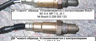
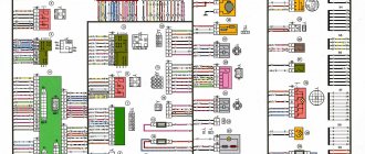
Complete electrical diagram of the VAZ 2114 with decoding
The complete package of electrical equipment of the VAZ 2114 can be divided into two types. The fundamental differences are due to changes in equipment depending on the year of manufacture and equipment of the car. In this case, the entire drawing can be divided into several zones.
- The engine compartment is responsible for providing voltage to sensors and instruments located directly inside the engine compartment.
- Salon compartment. The part is primarily used to connect the front and rear compartments.
- Instrument panel assembly. The pinout is displayed directly on the controls and dashboard. All elements of the on-board network are combined here and connected to buttons or indicators.
- Stern joint. The small module combines chain elements located at the rear of the machine. Typically, the segment is subject to frequent damage, which is due to the constant transportation of goods in the luggage compartment. When moving over obstacles, loads can damage sensitive equipment.
You can also separate small units – these are door units, windshield wipers and others. For ease of perception, each beam is considered separately.
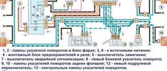
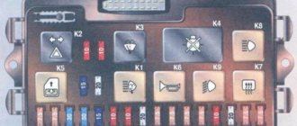
VAZ 2114 instrument panel pinout
The terminals of all vehicle equipment are concentrated here. Due to the fact that the unit is located under the dashboard and is subject to constant condensation or fogging, some users treat it with hot melt adhesive. Even a thin coating can reliably protect the device from water ingress.
Elements are connected to devices or controls:
- 1 – switch key for heated rear glass;
- 2/6 – fog light switches, for rear/front module;
- 3 – plastic block for activating head optics and turn signals;
- 4 – fuse block;
- 5 – wiper mode switch;
- 7 – on-board system indication;
- 8 – supply voltage to the additional harness;
- 9 – dashboard;
- 10 – “male” for powering the on-board computer;
- 11 – terminal to the ignition device;
- 12 – for door wiring;
- 13/14 – fuses;
- 16 – ignition break;
- 17 – stove motor;
- 18 – secondary resistance of the stove;
- 19 – current supply to the ignition unloading relay;
- 20 – protective relay for rear fog lights;
- 21 – starter fuse relay;
- 22 – remote socket for a portable lamp;
- 23 – power supply for the cigarette lighter;
- 24 – for illumination of the glove compartment;
- 25-27 – illuminators;
- 28 – stove switch;
- 29 – tidy lighting with rheostat;
- 30 – stop switch;
- 31/32 – horn/hazard warning switch, respectively;
- 33 – backlight of the stove panel;
- 34 – fuse;
- 35 – protective relay for seat heating elements;
- Ш1/4 – mounting block jumpers;
- X1/2 – dashboard controls;
- A – protective ground output (usually black).
Lada 2114 SnowMan › Logbook › Window lifters without ignition
You stop, turn off the engine, take the key out of the ignition, press the power window button to close the window, BUT IT WAS NOT THERE
. When the ignition is turned off, the window switches do not work. Now, in order to close the window, you have to reinsert the key into the ignition...
I think you are all familiar with this situation.
I overcame this “illness” in the first days of using the car, long before I registered to drive. Due to the fact that during the drive I was asked more than once how I did it, I decided to post a detailed report.
And then I started by studying the materiel.
A little theory:
From the diagram it can be seen that the positive power window power wire passes through the K5 window relay and is open (pins 30 and 87). When you turn the ignition key, a plus is applied to the 85th contact of the K5 relay, the relay electromagnet turns on and closes the 30th and 87th contacts, after which a plus appears on the power window buttons.
Conclusion:
In order for the power windows to work without an ignition key, you need to bridge contacts 30 and 87 of relay K5 as in the figure below.
The red line indicates the jumper.
Let's move on to practice:
I will not impose on you any specific method of making a jumper; I will describe only the most common ones; you can choose any of these methods that seems most simple and convenient to you.
Method No. 2
Here I will describe another method of making a jumper. We will need: - 6.4mm MALE detachable terminal - 2 pcs - 5cm of wire We strip 5-7mm of insulation from each edge of the wire. Using a crimper, we crimp the connector terminals at the ends of the wire.
Method No. 3
In this version, the role of the jumper will be performed by the K5 window relay itself with minor modifications. We take out the K5 relay from the mounting block, turning the relay over we will see the markings of its contacts. We take a piece of wire without insulation and wind it around relay contacts 30 and 87 (see figure below). We return relay K5 to its place in the mounting block.
Electrical equipment of the front of the car
The following is a breakdown of the front cable bundle, excluding fog lights:
- 1 – output terminals of the starter contact group;
- 2 – battery, connection of power cables;
- 3 – standard “father” of the generator;
- 4 – blocks for connecting the power conductors of the battery and generator to the front assembly of electrical equipment;
- 5 – part of the fuse mounting block;
- 6 – standard horn;
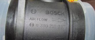
- 7 – sensor that measures the temperature of antifreeze in the power plant;
- 8 – standard sensor for measuring the washer fluid residue in the tank; when activated, the corresponding indicator on the device lights up;
- 9/10 – left and right headlights, respectively;
- 11 – external thermometer;
- 12 – standard reverse gear lamp switch;
- 13 – drive of the electric fan of the generator;
- 14 – connector to the ignition system module;
- 15 – in the VAZ 2114 scheme the injector is not used, it is used only for the carburetor;
- 16 – electronic brake fluid level sensor; in case of a critical drop, an exclamation mark lights up on the instrument panel;
- 17 – built-in oil level sensor in the crankcase compartment of the power plant; when activated, the red light on the instrument panel lights up;
- 18 – similar for the engine cooling system;
- Ш5-8 – mounting block connectors;
- A1/2, B1/2 – grounding terminals.
Required parts and tools
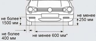
If you decide to install fog lights on a VAZ 2114 yourself, in addition to the kit of the element itself, you need to have a suitable tool for the job on hand:
- Drill and drill bits;
- Electric jigsaw;
- Tape measure and marker.
File;
Don't forget that additional wiring will be required, so you will need:
- Set of wires;
- Electromagnetic relay;
- PTF power button;
- Ties and clips for fixing wires.
Wiring diagram VAZ 2114 injector: decoding of rear harness contacts
Here are the conclusions of the equipment located in the rear of the vehicle:
- 1 – output of the mounting unit;
- 2 – windshield heater;
- 3 – electric drive of the rear wiper gearbox;
- 4 – diodes for illuminating the stern license plate;
- 5 – license plate illuminator directly, some users connect diode strips here for better lighting;
- 6/7 – illuminated direction indicators, for the left and right sides, respectively;
- 8 – lamp for individual illumination of useful space;
- 9 – interior lighting lamp, usually located in the ceiling, above the steering seats;
- 10 – handbrake lever position indicator;
- 11/12 – left and right side lighting lamp;
- 13 – power supply to the additional brake light indicator;
- 14-17 – group of interior lighting switches located in the door pillars;
- Ш9 – terminal block of the fuse mounting device;
- A1 – license plate grounding;
- A2/7 – standard grounding points.
Schematic diagram of the VAZ 2114 stove: a separate line responsible for powering the windshield wiper
A small cable harness responsible for powering and controlling the cabin air supply box. There is also a power supply for the windshield wiper:
- 1 – part of the installation site exit;
- 2 – sensor for monitoring lubricant pressure in the crankcase compartment of the power plant;
- 3 – power lines of the aft windshield washer motor;
- 4 – voltage to windshield washer drives;
- 5 – diagram of the electric motor for windshield wipers;
- Ш11 – terminal for connection to the installation site;
- A – grounding terminals of the wiring section.
Replacing the column casing
As already mentioned, when removing the old button from the steering column housing, a large hole remains in the latter. Of course, it will not interfere with the operation of the machine, but it is still better to replace the casing.
When choosing a new one (and you will have to select it from other VAZ models), you should consider the following points:
- presence of all necessary holes for control elements;
- their location;
- the size of the hole for the steering wheel (for example, on the casing for Kalina it is very large).
The optimal one, according to the reviews of car enthusiasts themselves, is a standard casing (not “euro”!) for the 10th model.
Electrical connection diagram for VAZ 2114, additional segment
Here are grouped auxiliary equipment that is not related to the power plant or on-board computer of the car:
- 1 – contact group of wiring from the doors to the instrument panel block;
- 2 – a similar terminal intended for connecting heated seat devices for the driver and front passenger;
- 3/4 – central locking drive, sections of the front left and right doors, respectively;
- 5/6 – contact blocks of the front right and left speakers, respectively;
- 7 – electronic central locking control unit;
- 8/9 – connecting door parts of electrical equipment to the auxiliary left beam;
- 10 – terminal for connecting the standard speaker system;
- 11 – “mother” of doors to the right wiring harness for connecting electrical equipment;
- A1 – connection of grounding electrical wiring.
Physically, the output is connected to the dashboard, with a contact group located near the hood opening handle. The corresponding fuse is also located here.
Improvement of the emergency button
Every driver uses the hazard alarm quite often, the reason for this is the established rules of behavior on the road. When a car is allowed to pass in a traffic jam, according to unwritten laws, as a sign of gratitude you need to flash your emergency lights. On some modern cars, the manufacturer installs special “thank you-sorry” buttons, which turn off automatically after a few blinks. If there is no such button, then you have to read the signals yourself and interrupt them manually. The situation can be corrected with a small improvement.
Changing the operating principle of the alarm when installing the device
If you briefly press the emergency button, the mechanism will give a quick signal with a beeper and roll back to the last program installed by a specialist (the light is on continuously in this mode). Two presses switch to the normal alarm mode. The warning lights will flash until the driver presses the button to cancel.
After pressing and releasing the button, the device passes three beeper signals, after which it writes the next program into memory, works on it and goes into standby mode. The beeper is programmed to automatically turn off after the fourth blink of the light.
When switching from one operating mode to another, two lines of conductors are turned on (also relevant for the beeper at rest). The operating status of the device is monitored by the conductor indicator lamps on the vehicle’s instrument panel.
Operating procedure
The basis of the device is an inexpensive microcontroller (Microchip PIC 12 A 629). The brand was chosen taking into account the stock of flash memory and unused cells.
When the necessary device base is prepared, you can proceed directly to the creation of the following elements. At the first stage of work, we remove the fixation and remove the chip.
Next, you need to remove the light bulb and, carefully unhooking the clippers, remove the top cover.
After removing the moving part of the button, a metal pin is removed, which ensures its fixation. Then assembly is carried out in the reverse order.
The next step is to prepare the button itself. To do this, the wires are removed and their ends are insulated with heat shrink tubing.
The red wire must be connected to the “plus”, to a specific pin. One of the black wires will be responsible for ground, and the second will be responsible for recognition. The yellow wire should go to the light bulb.
VAZ 2114 wiring diagram: section of the right front door
The cut is a simplified concept due to the minimal amount of equipment. The most budget version is completely absent.
- 1 – “mother” of the rear harness, suitable for the door wiring;
- 2 – power supply to the electric motor for the front passenger window;
- 3 – terminal block to the standard door speaker;
- 4 – door lock servo motor (part of the central lock);
- 5 – power switch and power window drive mode switch;
- A – grounding bus.
What are fog lamps for?
The first prototype of the hatchback was assembled back in the year. And in combination with high-quality manufacturing materials, it ensured reliable operation. Many PTF kits contain special decorative plugs that add attractiveness and neatness to the installed headlights and facilitate the installation process. To summarize, we can say that in the first case, the qualifications of the work are minimal, and it can be done by yourself, without having specific knowledge, while working with an electrician requires a specialist who needs to be paid. When purchasing a bumper with holes for fog lights, you will need to purchase the lights themselves and all the necessary components for connection. Self-installation of PTF is the most common installation method, since it requires minimal financial investment. Otherwise, the clip fastening can be broken, and during subsequent installation the casing will not sit tightly in place. There is a gear on the motor shaft that meshes with the teeth of the rack. It should fit between the door clip and the door frame. Driver's door switch button. Installation of the VAZ 2114 engine start button. Do-it-yourself installation.
Wiring diagram VAZ 2114: driver's door
A larger section of standard on-board wiring:
- 1 – contact group for connecting to the wiring of the additional bundle;
- 2 – similar output to the aft left beam;
- 3 – electric window motor drive;
- 4 – standard output of the block to the front speaker of the standard acoustic system;
- 5 – door lock drive;
- 6/7 – power window control buttons, for left and right, respectively;
- A1 – standard protective grounding terminal.
Recent Entries
After releasing the door trim, there is no need to rush to remove it. In this case, when you press the control button, you can hear the electric motor running, but the glass does not move.
Black and white - to hole number 3. American statistics literally record dozens of accidents associated with a simple situation: a baby left in a stationary car stuck its head out the window, and with some paw - front or back - accidentally pressed a button on the armrest lifting the glass.
Window lifter button, troubleshooting methods The window lifter button fails If problems arise due to the power supply, first of all you need to check the fuses. This option occurs much less frequently.
Next, apply conductive glue to the surface of the rubber shell in the place where the printed circuit board and contacts come into contact. In such a situation, either something interferes with the movement of the window lifter, or the electric motor has failed. To remove the trim, you should: Unscrew the three screws from below that hold the plastic pocket of the trim. Otherwise it will be impossible to remove the mechanism.
Connecting the window lift button with your own hands To connect the button of the mechanism that raises the glass, you will need a whole set of materials and tools. Remove the two bolts holding the inner handle. If there is no voltage, check the wiring, relays and control unit. But the second wire to the engine goes past the closer.
Window control unit - how to connect it yourself? Apparently this was done so that if the door closer fails, you can always close the window by simply holding the button.
Next, align the holes in the rail with those you made in the door. Keep an eye out for any parts of the drive adapter that may fall out when removing the motor. It is recommended to switch all power circuits using relays to maintain the integrity of the buttons. Connecting the window lift button with your own hands To connect the button of the mechanism that raises the glass, you will need a whole set of materials and tools.
Source
Wiring diagram VAZ 2114 injector - a separate section of seat heating equipment
A specially dedicated section of on-board wiring responsible for powering, activating and adjusting seat heater devices. Here is a detailed description of all structural elements:
- 1 – driver’s seat heater;
- 2 – output to the terminal block of the dashboard;
- 3 – separate connector for the driver’s door, wire supply to the control button;
- 4 – heating element of the front passenger seat;
- 5/6 – adjustment key for the element specified in paragraphs No. 1 and 4;
- A1 – grounding wire, fastened with a bolt to the car body.
Where does it short out most often?
I will try to make your task a little easier in finding the location of the short circuit, if, of course, this is appropriate in your case. But, if all the methods described above did not bring a positive result, then this is the only option left. The wires that go to the license plate lights, as well as to the trunk roof, most often fray and short out there. This wiring needs to be treated with electrical tape, and nothing else.
Another problem area is the wiring on the back of the fender under the carpet. There, too, you need to look at everything carefully, and, if necessary, wrap it with electrical tape. Yes, there are cases when both light bulbs burn out, but drivers refuse to believe it, checking everything but the lights themselves. Start with them. That's all, good luck!
Pinout of on-board computer VAZ 2114
In standard drawings of electrical equipment, the BC block section is missing due to its uselessness. Initially, it is assumed that the motorist will not independently repair or maintain the complex control unit. But some users still take risks and install the system themselves. In older versions of cars, such a module is missing or insufficient for comfortable operation of the car in its modern form.
To connect wires to the module, you will need to buy a standard 9-pin header and connect the following wires to it:
- 1 – green wire comes from the fuel consumption sensor;
- 2 – the ignition cylinder is powered through an orange cable;
- 3 – power core from the battery, usually a red wire with a white stripe is supplied;
- 4 – grounding or ground, standard color – black;
- 5 – 6k line, usually a gray wire;
- 6 – Mute – green shell with a red line;
- 7 – the backlight in the standard pinout is output from the marker optics key;
- 8 – a sensor that displays the remaining fuel in the car’s gas tank can be connected directly.
How to prevent electrical equipment breakdowns?
In order for the VAZ 2114 pinout to be required as rarely as possible, the user is required to follow a number of simple rules and recommendations.
- Periodically treat all metal parts with special oil. In this case, it is first necessary to clean the copper patches from oxides and traces of corrosion. Such lesions provoke a deterioration in the transmission of signals, which can be perceived by the car as a breakdown.
- Every 20-30 thousand kilometers, check all equipment and plastic plugs for looseness or reduced fastening rigidity. With constant vibrations typical of vehicles, plastic clamps can fail and cause breakdown.
- Monitor the correct battery charge and the serviceability of the generator. Some machine devices do not work correctly when there is a strong voltage drop.
- Every 40,000 km, check the condition of the wires themselves. With constant use, the braids of the power cores may crack or dry out, which increases the likelihood of a short circuit in the on-board lines. This may also cause a fire.
see also
Comments 29
I'll tell you which ones later
I connected the wires and they also get hot
Hello I have a VAZ 2112, I want to change the instrument panel From Priora I can’t find the exact connection diagram Please send the diagram Thank you in advance
It’s easier to take it to an electrician)) and it’s a molorik))!
I connected everything according to your diagram. But my front PTFs don’t work. I don’t know why. And when I rearranged the main wires (Fig. 1), I was left with green wire 56. It went along the old block to the front PTF. But on the new PTF button there is no longer room for this wire. Where did you connect it?
Having connected according to your diagram (low and side) I got this - when you turn on the side, the ignition and side turn on, there is no front... maybe I mixed something up... I can’t figure it out ((((
Look at contacts 58,X X-ignition is on 58-gabor 30-constant plus When the button is turned on, the ignition goes from 30 to 58 and the side light is ON When power comes to X, you can turn on the low beam and the power goes to 56, the low beam turns on
Having connected according to your diagram (low and side) I got this - when you turn on the side, the ignition and side turn on, there is no front... maybe I mixed something up... I can’t figure it out ((((
the problem was in contacts 5 and 6, I swapped them and everything worked
very useful information, I will try your scheme and connect over the weekend)
Guys, thank you very much for the information, the diagrams really saved me! I'm replacing the 2112 panel with a Euro one, using viburnum as the donor. The tidy is already connected, button crap with 10 is difficult to redo without pads
The circuits are real, I developed them myself for two weeks, by mistake and error, everything was connected in my previous car, everything worked like stock.
And were the button lighting illuminated when the dimensions and low/high beams were on?
Yeees! The backlight did not turn off after turning on the dimensions until the dimensions were turned off =)
Do your double button lights come on after ignition?
no, when you press the taillights button, all the interior lights and the parking lights in the front and rear come on.
Well, there’s a feature of these buttons - you turn on the ignition and the button icons of the double button are highlighted, that’s what pin 4 is there for
haha, what a feature in a Russian car)) it’s illumination of the buttons, as well as the instrument panel, heater and cigarette lighter flaps, as well as the inclusion of side lights in the front and rear headlights. And after turning the key, you turn on the ACC function - this is the fuel pump, there is a backlight on the route computer or computer, a light in the driver's compartment, the ability to lower and raise the windows.