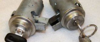
The ignition switch in cars of the VAZ family fails from time to time due to weakening of the contact posts or burning of the contacts inside it. It also happens that the cams of a plastic roller are produced. You can disassemble the lock and clean it, but it’s better to just replace it with a new one, considering that it costs pennies compared to imported locks.
But if connecting the wires together did not result in the starter operating (or it did not turn on the first time), check the solenoid relay on the starter. The contact spots on it may also burn out, which will prevent the circuit from closing normally. Alternatively, you can use a screwdriver to short-circuit the two large terminals on the solenoid relay (before doing this, put the car in neutral and use the handbrake). When closed, the starter should begin to spin vigorously. If this happens, remove and change the solenoid relay. If the starter rotates “sluggishly” when it closes, you will have to remove it and check the condition of the brushes.
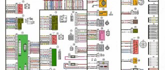
All operations are performed with your own hands, without the help of car service specialists. Moreover, the price of an ignition switch on a VAZ2106 is up to 100 rubles. To replace it, you will need to know the pinout of the wires coming from it, for which the editors of the site 2 Schemes.ru have prepared a large reference material.
The ignition switch is designed not only to start the engine - it performs several functions at once:
- supplies voltage to the vehicle’s on-board network, closing the circuits of the ignition system, lighting, sound alarm, additional devices and instruments;
- at the driver’s command, turns on the starter to start the power plant and turns it off;
- turns off the power to the on-board circuit, preserving the battery charge;
- protects the car from theft by fixing the steering shaft.
This option is for those who want to illuminate the BSK block without plexiglass
We erase the front plate with a stationery knife.
Print out the same drawing again, but on matte paper.
It goes something like this
Then I made holes in the case with a soldering iron.
To diffuse the light, I inserted pieces of transparent plastic into these holes (cut from a simple CD box) and made one side matte with a knife, but better with sandpaper
Now we are illuminating the Vase, which I forgot to photograph.
To illuminate the BSK module, I took a diode strip (2 pieces from it)
There are no pictures, so I took approximately the same module as a base and added LED strips there. I think the meaning is clear.
The strips need to be glued between the door LEDs
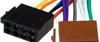
I soldered the backlight wires to pins 1(+) and 3(-) to these
Now the drawn car on the block will glow brightly when the ignition is on.
In order for the car to not glow so brightly, I soldered a 620 Ohm resistor to the positive wire.
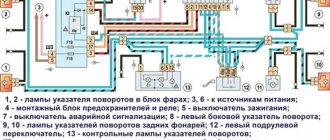
Pinout of contacts BSK Auto VAZ 2110
Let's put everything back and look at the result.
By the way, you can use plexiglass in the form of small pieces for each light bulb. Then the glow of adjacent LEDs will also not interfere with each other.
I was sitting, leafing through Avito, and then I liked the “Indication unit for the on-board control system of VAZ 2110 cars.” And somehow I wanted to put it in my car.)
Having searched and looked at the original diagram of the VAZ 2110, everything turns out quite simple.
As a result, this is the idea. 1 - to +, it’s probably best to put it on the ignition, so that it only works when the ignition is on. 2 - not used. 3 - output to ground. 4 — I’m too lazy to deal with the headlight fault relay, so I’m thinking of using it for something else, or not connecting it at all. 5 - also goes to +. 6 - here according to the standard for the lampshade, but I don’t have any, so we’ll leave it for now too. 9 - to the oil level sensor, but we have a pressure sensor, so we’ll throw it on the sensor for the emergency oil pressure warning light. 10 - to the coolant sensor in the expansion tank, “lights up in orange when the level of coolant in the expansion tank on a cold engine drops below the permissible limit” but again, I don’t have one, so a sensor for the coolant overheating warning lamp will go to it. 11 - to the washer fluid sensor, the entire washer system asks to be redone, so we’ll probably screw the sensor in too. 12 - to the sensor for unfastened seat belts, oh, if only they were still there. But they will be, so we’ll use it when we install the belts and screw the sensor to them. 13 — brake pad wear sensor, the front brakes are still drum brakes, so I’ll throw it on the emergency condition sensor of the hydraulic brake system.
Read more: Program for scanning a car on a laptop
Along the list we skipped a couple of numbers, now they... 7, 8, 14, 15 - door sensors, since there is an idea to install a central lock, but they will most likely display which of the doors are open/closed, or we’ll throw it at the open/closed door sensor as per the standard.
A little later I will redraw the general electrical diagram. wiring by including this block in it. All that remains is to figure out where to place it.