Let us remind you that the emergency signaling is carried out by the same electrical circuit that turns on the direction indicators. Therefore, it is possible that problems in the electrical circuit will be similar. But before we start talking about malfunctions, let’s remember what the electrical circuit of the alarm on the VAZ 2114 looks like and how it turns on. Also from the same article, the reader will learn how to move the emergency button from under the steering wheel to the dashboard and install an elegant Euro button.
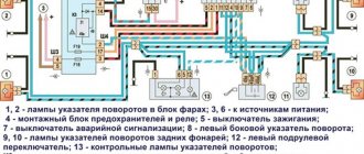
Emergency gang diagram for VAZ 2114
Electric current from the power source (3) enters the mounting block (4), where it passes through two fuses and a relay to buses 2 and 4 through the X11 chip of the mounting block. From the mounting block, the wires go to the ignition switch and hazard warning switch, which has several modes. There is another turn signal switch in the electrical circuit, which is called the left steering column switch (12). The turn signal headlights in the diagram are indicated by numbers:
- 1,2 – front,
- 8, 11 – side,
- 9.10 – rear.
Useful: Where
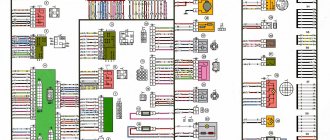
To complete the picture, we provide, as an illustration, a diagram of the location of fuses and relays in the mounting block.
How does an electromagnetic-thermal relay work?
These devices are no longer used in modern cars. However, in older models they are still widely used.
The design of the electromagnetic-thermal relay is quite simple; it uses a circuit for connecting turn signals through an electromagnetic-type relay. It is made in the form of a cylindrical core, and a thin copper wire is used as its winding. At the top of the core there are two groups of contacts, and metal anchors are installed on each side. The first group of contacts closes the circuit where there is a control light located on the instrument panel. With the help of other contacts, the circuit with the lamps in the direction indicators is closed. They are the ones who provide the flashing mode.
A thin nichrome string is attached to the anchor of the main group of contacts. It pulls the armature away from the contact, which is located on the core. Thus, the circuit will be open, which is its normal position. The core itself is installed on a special insulated platform, where the opposite end of the string is also fastened. During operation, an electric current passes through the string, since it, together with the resistor, is in the switch circuit. All elements of the device are housed in a cylindrical metal case.
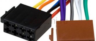
Connection diagram for Euro button on VAZ 2114
The figure shows a diagram of connecting turn signals and emergency lights with a new Euro button.
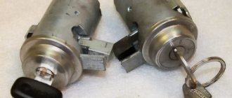
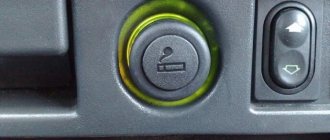
The location of the original emergency button caused a lot of complaints from car owners.
The AvtoVAZ emergency flasher has another significant drawback - its tendency to stick. That is, you turn it on, but how to turn it off is a problem. You have to arm yourself with tools, remove the button from under the steering wheel and fix the loose fastener. This is what causes the sticking.
Useful : The emergency lights and turn signals on the VAZ 2114 do not work
Fortunately, the same engineers provided one slot for a button on the dashboard. Obviously, they left this slot for installing additional equipment in case the car owner wants to modernize the interior, or do tuning in it, and add some cutting-edge device. For now, this nest is closed with a plug (pseudo-button). Almost all car owners bring their emergency lights here, since pressing on them here is much more convenient than somewhere under the steering wheel.
At the beginning of the section there is a diagram of the VAZ 2114 emergency gang, according to which the Euro button will be redone. First, at the nearest car market or in an online store that sells spare parts, we find the Euro button.
You will also need a four-pin relay with a connector (with a block). First, the old button must be dismantled and the wires removed from it. We won't need it anymore. And the wires with contacts will still serve. For ease of connection, the wires can be labeled. Below is a diagram for connecting an emergency light on a VAZ 2114. The diagram shows how to move the wires from the old button to the new one and connect a four-pin relay.
In accordance with the diagram of the emergency signal button on the VAZ 2114, the wires are transferred to the new button and connected to a four-pin relay.
You will get a kind of garland of wiring and devices. This garland is to be mounted in the dashboard of the car. The chip from the old button is removed and the ends of the garland are inserted into its connectors.
If everything was done correctly, the button will work. Now you have to insert the button in place of the plug and remove the wires under the dashboard. By the way, the minus is taken from the minus of the on-board computer. To insert the emergency signal chip into its place, the wires will have to be disconnected for a while. The wiring harness runs from the steering column under the on-board computer. To do this, you will have to remove the corresponding casings and shields. Then the wire terminals are inserted into the connectors again. accidents
What to do with the hole from the old button? Car owners solve this problem in different ways. Some people find a casing of the appropriate size, but without a hole for the button, while others install a plug that matches the color of the casing. On the euro button itself there is a red indicator light, by which you can understand that the emergency lights are on. In addition, when the emergency lights are on, both turn signal arrows on the dashboard flash. The network offers other options for installing the Euro button. For example, with connecting diodes. But in this case, the turn signals light up when the ignition is off, which is not very convenient. The basis is this wiring diagram for the Euro emergency flasher button of the VAZ 2114
To get to the standard button, remove the casing. We take out the old button, its upper part can be thrown away, the spring is not needed. The lower part remains. Through the side wall removed from the driver's side, we pull out the chip with wires under the on-board computer. Here, too, the partition is removed. The wires are soldered in the following order:
- We connect contacts 4 and 8 through an additional wiring;
- The cathodes from the diodes are connected to contacts “1” and “3” by soldering, and the anodes are soldered together;
- The wires of the Euro button with contacts “D” and “2” are connected by soldering to the free anodes of the diodes.
- There is an indicator on the Euro button, but the light bulb is not inserted into the dashboard. It is necessary to insert the light bulb and connect wire 2 to the dashboard;
- The wire of contact “1” on the button is connected to wire 7 on the wiring harness;
- Contacts “A” and “B” are routed to ground and backlight, respectively. To do this, the terminals with wiring must be soldered to contacts A and “B”.
- The resulting wiring harness is connected to the supply line.
To ensure reliable soldering, the contact surfaces are treated with LTI-120 soldering flux;
Improvement of the emergency button
Every driver uses the hazard alarm quite often, the reason for this is the established rules of behavior on the road. When a car is allowed to pass in a traffic jam, according to unwritten laws, as a sign of gratitude you need to flash your emergency lights.
On some modern cars, the manufacturer installs special “thank you-sorry” buttons, which turn off automatically after a few blinks. If there is no such button, then you have to read the signals yourself and interrupt them manually.
The situation can be corrected with a small improvement.
Changing the operating principle of the alarm when installing the device
If you briefly press the emergency button, the mechanism will give a quick signal with a beeper and roll back to the last program installed by a specialist (the light is on continuously in this mode). Two presses switch to the normal alarm mode. The warning lights will flash until the driver presses the button to cancel.
After pressing and releasing the button, the device passes three beeper signals, after which it writes the next program into memory, works on it and goes into standby mode. The beeper is programmed to automatically turn off after the fourth blink of the light.
When switching from one operating mode to another, two lines of conductors are turned on (also relevant for the beeper at rest). The operating status of the device is monitored by the conductor indicator lamps on the vehicle’s instrument panel.
Operating procedure
The basis of the device is an inexpensive microcontroller (Microchip PIC 12 A 629). The brand was chosen taking into account the stock of flash memory and unused cells.
When the necessary device base is prepared, you can proceed directly to the creation of the following elements. At the first stage of work, we remove the fixation and remove the chip.
Next, you need to remove the light bulb and, carefully unhooking the clippers, remove the top cover.
After removing the moving part of the button, a metal pin is removed, which ensures its fixation. Then assembly is carried out in the reverse order.
The next step is to prepare the button itself. To do this, the wires are removed and their ends are insulated with heat shrink tubing.
The red wire must be connected to the “plus”, to a specific pin. One of the black wires will be responsible for ground, and the second will be responsible for recognition. The yellow wire should go to the light bulb.
We recommend: Description of Daewoo Nexia fuses: characteristics, diagram, photo and video
Next you need to install the finished button in the car.
At the final stage of the work, attach the buzzer to the wiring harness using a thermal pestle or a simple clamp. The short ends must be soldered according to the diagram to the microboard, and the long ends must be attached to the car chip. It is recommended to install wires in a twisted manner.
Breaker relay malfunctions
Malfunctions in the operation of the turn signal or low/high beam relays in the VAZ 2106 are quite rare. These mechanisms are quite reliable, but, being part of the overall electrical circuit of the car, they are not immune to problems such as overvoltage, breakdown, etc. In fact, the products are non-repairable - it is almost impossible to eliminate damage to the coil or contacts qualitatively. In other words, if a defect or malfunction is detected, the mechanisms are simply replaced with similar ones, selecting them by catalog number:
- for the turn signal relay - 231.3747-10(11) or 23.3747-10(11);
- for the lighting breaker relay - 113.3747-10(11) or 90.3747-10(11).
The number at the end of the designation indicates the design of the device case: the 10th modification is equipped with a mounting flange, while the 11th version does not have it, which is compensated by the increased dimensions of the case. Also, when choosing electronic relay breakers, you should remember that rotary models are compatible with alarm relay units, and lighting ones are compatible with devices for switching on the fan motor, horn, and rear window defroster. A malfunction of the relay unit may be indicated by problems in the operation of the light bulbs controlled by it due to the impossibility of closing the circuit or, conversely, opening it.
For rotary relays, typical signs of a malfunction may include flashing too fast or too slow, or no clicks. But the rapid blinking of the control light on the dashboard indicates that the lamp in the headlight has burned out, and not the relay itself.
The central part of the electrical equipment diagram of the VAZ-2106
The central piece of the circuit mainly consists of light on/off switches and switches for supplying current to the system.
The main wiring elements are indicated by the following numbers:
- Kit with main fuse block (30);
- Light switches in the car's reversing headlights (31), operation of warning lamps when the hand brake is applied (32);
- Types of plug sockets for portable lamps (33);
- Equipment for operating the turn signal and hazard signal (34);
- Design of the electric motor of the stove (35) and the terminal for turning off the brake light (36);
- Current supply relay for heating the rear window (37);
Tip: depending on the modification and year of manufacture of the VAZ-2106, the type of relay and its position in the network may change. To repair this spare part, it is best to use the diagrams that come with the machine.
- Set of resistors for the VAZ 2106 heater electric motor (38);
- Wiring to the light bulb in the glove box (39);
- List of switches for exterior lights (40), heating the rear surface of the glass (41), as well as the ignition system (42);
- A set of switches from low to high beam (43), a windshield wiper (46) and a car turn indicator arrow (44);
- Special types of vehicle horn switches (45), universal windshield washer switches (47) and dashboard light and emergency signal controls.