Which sensor is responsible for engine speed? List and necessary information
If problems arise with the engine, you may be asked which sensor is responsible for engine speed.
Often it is these electronic devices that drivers are guilty of in the first place. But the sensors should be checked last. The speed can fluctuate for a variety of reasons. First you should make sure there are no other damage. Often problems with speed begin after refueling with low quality fuel.
In this case, the injection system is simply not able to produce a normal mixture.
Idle speed sensor
It should be noted that if it is damaged, the speed will float mainly at idle. But in any case, the check should begin with DXX. To do this, you need to remove the wire block from the sensor. Then the voltage is checked. To do this, one terminal of the wires is connected to ground, that is, applied to the engine. The second wire is connected to the sensor and the voltage is measured.
The multimeter must output a voltage of at least 12V. If the indicator is lower, then the battery may be low. After its charge is restored, engine operation may be restored. You also need to check the resistance at the terminals, it should be 53 ohms. Measurements must be made on paired contacts. You need to change the sensor if the resistance is lower or higher.
High idle speed VAZ 2110-12 - causes and solutions
Almost every owner of a domestic VAZ has encountered the problem of high idle speed. That is, when starting the engine, the speed is increased as expected, but when warming up, it does not fall below 1500 or 1000 revolutions, which is not normal. There may be several reasons for this - including a malfunctioning TPS and idle air control.
To fix the problem, you should diagnose the main components and components that affect the increase in speed.
- Why might there be high idle speed?
- Where are the IAC and TPS sensors located?
- Diagnostics of the IAC sensor VAZ 2110
- IAC check method 1
- IAC check method 2
- IAC test method 3
- Diagnostics of TPS VAZ 2110
- Symptoms of TPS malfunction
- Which TPS sensor to choose for replacement
- Replacing the Throttle Position Sensor on a VAZ 2110
- Which IAC sensor to choose for replacement?
- Replacing the IAC sensor VAZ 2110
Why might there be high idle speed?
One of the main reasons may be the failure of the IAC, which is responsible for adjusting the engine speed at idle. If the sensor malfunctions, the speed can “float”, rise and fall spontaneously. If the sensor completely fails, the car may simply stall at idle.
Also, increased speeds can be caused by a malfunction of the throttle position sensor (TPS). Over time, moisture gets under the sensor, which leads to the formation of oxide and rust on the regulator rod. To check this, you need to unscrew the sensor and carefully inspect it and the rod. If rust is found on them, they should be treated with penetrating lubricant or WD 40.
As a rule, the problem of increased speed on the VAZ 2110-12 lies precisely in these two sensors. Therefore, first of all, you need to pay attention to them.
Where are the IAC and TPS sensors located?
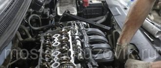
So, first, let's check the IAC sensor. It is located on the throttle assembly below the TPS sensor. Dismantling it is very simple - remove the block from the sensor and use a Phillips screwdriver to unscrew the two bolts securing it. Then we pull out the sensor or perform diagnostics on it, read about this below.
The throttle position sensor is located above the IAC and is also secured with two bolts. It unscrews quite easily; there is no need to remove either the pipe or the throttle itself. Disconnect the block, unscrew the two bolts and pull out the sensor.
To make sure that the problem with high speed is really in one of these sensors, and maybe in each other at once, you should diagnose them.
Diagnostics of the IAC sensor VAZ 2110
There are several ways to check the idle speed control. To check we need a multimeter. First, let's describe the simplest way:
IAC check method 1
- Disconnect the block and unscrew the sensor
- Turn on the ignition
- We connect the block to the removed sensor, the needle in it should extend. If this does not happen, then the sensor is faulty.
IAC check method 2
- Disconnect the negative terminal of the battery
- Using a multimeter, we measure the resistance of the external and internal windings of the IAC, while the parameters of contacts A and B, and C and D should be 40-80 Ohms.
- If the instrument scale is zero, it is necessary to replace the IAC with a serviceable one, and if the required parameters are obtained, we check the resistance values in pairs B and C, A and D.
- The multimeter should detect an open circuit
- With such indicators, the IAC is serviceable, and if they are absent, the regulator must be replaced.
IAC test method 3
- Disconnect the block from the sensor
- Using a voltmeter, we check the voltage - the “minus” goes to the engine, and the “plus” to the terminals of the same block of wires A and D.
- The ignition is turned on, and the received data is analyzed - the voltage should be within twelve volts, if less, then most likely there are problems with the battery charge. If there is no voltage, then you will have to check both the electronic control unit and the entire circuit.
- Then we continue the inspection with the ignition on, and analyze terminals A:B, C:D one by one - the optimal resistance will be about fifty-three ohms; During normal operation of the IAC, the resistance will be infinitely high.
Diagnostics of TPS VAZ 2110
To diagnose the sensor we need a voltmeter.
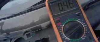
- It is necessary to turn on the ignition and check the voltage between the slider contact and the minus with a voltmeter. The voltmeter should read no more than 0.7 V.
- Now you need to turn the plastic sector, thereby completely opening the damper, then measure the voltage again. The device must show at least 4 V.
- Turn off the ignition and disconnect the connector from the sensor. We check the resistance between the slider contact and some terminal.
- Slowly, turning the sector, monitor the voltmeter readings. Make sure that the needle moves smoothly and slowly; if you notice jumps, the throttle position sensor is faulty and must be replaced.
Symptoms of TPS malfunction
- Deterioration of vehicle dynamics
- Floating idle speed
- Jerking during acceleration
- High idle speed, car does not slow down
- The engine may stall at idle
On throttle position
This sensor is designed for the controller to calculate the throttle opening level. It is installed on the throttle axis. When you press the accelerator pedal, it turns along with the throttle. Essentially, this is a variable resistor that, depending on the angle of rotation, changes the voltage level supplied to the controller.
It is checked this way. The ignition is turned on and the voltage at the sensor terminals is measured. It should fluctuate from 0 V at the starting position, to 12 V at the maximum. You can also measure resistance, but this is not necessary. If the voltage is absent or increases unstably, then the TPS is faulty and needs to be replaced.
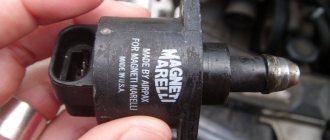
Mass air flow sensor
This sensor controls and normalizes the flow of air into the fuel mixture. Signs of its malfunction are the following problems:
- Unstable speed;
- Problems starting a warm engine;
- Reduced power.
This sensor is checked in different ways. The simplest of them is to turn off the mass air flow sensor and drive without it. If the negative aspects disappear, then most likely the reason is in the sensor. Also, sensor failure can be caused by poor-quality firmware. To do this, place a 1 mm thick plate under the throttle valve stop. At the same time, the speed should increase slightly. Then remove the chip from the sensor we are interested in. If the engine continues to run, the reason is the “crooked” firmware.
The test is also performed by measuring the voltage. To do this, take a multimeter; it should be set to a maximum voltage of 2 V. Next, measure the voltage at the terminals. On a new, fully operational sensor, it should fluctuate between 0.98-1.01 V. A malfunction of the mass air flow sensor is indicated by a voltage of more than 1.05 V. In this case, it should be replaced.
Innovations in motor control and new sensors
The automotive industry does not stand still, and people increasingly demand comfort in cars. Thus, automakers are adding new improvements in the design of the engine and related systems. Thus, German specialists began installing additional sensors on the cooling system and in the interior.
The driver sets the temperature of the car interior on a special console, and the electronic control unit, using an additional cooling sensor and an air conditioning indicator, regulates this value. But the disadvantage of these sensors is that they directly affect the starting of the engine, and in the event of a breakdown there will be problems with starting the power unit.
Another innovative indicator is the electronic engine control unit operation sensor. This sensor monitors the performance of the ECU and the wiring associated with it. Thus, failure of the sensor will be signaled on the car dashboard by a separate indicator.
In this case, it will be impossible to start the engine, since the indicator is located directly in the control unit, and without it, no engine system will work.
Auto engine speed sensor
When car enthusiasts have certain problems with the engine, they begin to wonder which sensor is responsible for engine speed, since the first suspicion often falls on these devices.
However, this is not always the case, because the speed can “float” for various reasons. It is best to first make sure that there are no other damage, and check the meters afterwards. One way or another, if you want to locate the sensor you need, you need to know what it looks like and where to look for it.
Basic Concepts
To synchronize the operation of the ignition systems, as well as injection, a speed sensor is provided, or, as it is called, a speed meter. It is he who transmits to the electrical unit that controls the engine the necessary data about what rotations the crankshaft is currently supporting.
This power unit meter is the most important element of the car, without which the interaction of many systems is essential, because it helps ensure the correct functioning of the entire car as a whole.
The car's electronic control unit processes the special signals that this meter sends to find out:
- amount of fuel injected at the moment;
- injection moment;
- time required to activate the adsorber valve;
- ignition timing (for gasoline engines);
- the angle of rotation of the camshaft during operation of the system to change the phases of the gas distribution mechanism.
To determine the performance of the meter, you need to know its location.
Starting the engine and malfunctioning sensors
There are several options for starting the power unit and the influence of sensors on the performance of the machine’s heart. Let's consider options for incorrect starting of the power unit, the influence of sensors and elimination methods:
- The engine starts, but a tripping effect occurs. In this case, sensors could fail: throttle position, IAC, DMVR, phases and, of course, the ECU.
- The engine does not start. This may be due to the failure of any sensor. So, to eliminate the malfunction, you need to gradually ring all the indicators using a multimeter, or connect to the control unit, which will indicate the error code and the sensor associated with it.
- Blocking the engine from starting by the electronic control unit due to the failure of several sensors or the accumulation of errors. To troubleshoot the problem, you need to connect to the car’s brains using an OBD cable, and use special equipment to carry out diagnostics that will show errors. By deciphering the codes, you can determine which indicators need to be called to fix the problem.
- The engine starts, but runs intermittently and stalls periodically. In this case, the problem may be hidden in the throttle position, mass air flow, oxygen sensor, crankshaft position and idle air control sensors. For quick and effective diagnostics, it is recommended to connect to the motor control unit and determine which indicator has failed.
If engine malfunctions occur, it may not even be the sensors, but often they are the cause of trouble. Therefore, before getting into the mechanical part of the motor, it is necessary to determine whether the problem lies in the indicators.
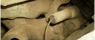
Location
The speed sensor, or induction meter, is usually located above the vehicle's marker disc.
The disk, in turn, may be located:
- on the flywheel;
- on the crankshaft inside the cylinder block - this happens with brands Ford, Opel, etc.;
- in front of the engine compartment on the crankshaft, together with the drive pulley for additional units (Jaguar, BMW, VAZ, etc.).
It is best when the marker teeth of the flywheel are intended only for measuring engine speed. It’s a little worse if the starter teeth are marker teeth: this feature is present in Audi and Volvo cars.
A slight curvature of a flywheel tooth or a small chip present on it can often cause a malfunction of the ignition system, due to which the power unit cannot operate at high speeds. In this case, chaotic sparking often occurs because the control unit incorrectly determines the number of teeth.
Important Features
It should be noted that on some cars the rotation speed sensor replaces the Hall meter: this device can transmit to the main control unit not only a signal about the valve timing, but also engine speed. If this is exactly the situation you have, then you can find the device near the camshaft.
If the crankshaft speed meter fails, you will not be able to start your car: after a thorough check of the ignition and fuel supply system, during which no significant deviations are found, it is recommended to check the performance of the speed sensor.
What sensors can be located in the engine
Different motors may have different numbers of sensors, the health of which can have different effects on the start and operation of the power unit. Generally speaking, any indicator can affect the good start of the engine. But, if you take it apart, each sensor has its own purpose, and therefore not all of them can affect the start of the car’s heart. Let's consider each sensor separately and its purpose in the operation of the car.
So let's start from the beginning. A motorist poured fuel into a car. Many modern cars are equipped with a fuel quality sensor. Such sensors can especially be found on German and American cars that are not adapted for our region.
When bad fuel enters the fuel system, the analyzer determines how high-quality fuel has entered the car. If the “bodyaga” has been flooded, the engine may start with difficulty or may not start at all. This analyzer can be located before or after the fuel filter.
The second most important indicator that can affect engine starting is the coolant temperature sensor. It is the malfunction of this indicator that can lead to the fact that the power unit will take a long time to start. This is due to the fact that the electronic control unit thinks that the engine is hot and injects insufficient fuel. Typically, this sensor is the most susceptible to failure.
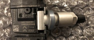
The next indicator that directly affects the normal start of the engine is the idle air control sensor. It determines how much of the fuel-air mixture is needed for normal engine operation at idle and during engine starting.
The knock sensor also affects the start of the unit. Typically, it is installed at the top of the engine and picks up the vibrations generated by the engine. If the sensor sends a signal to the computer that detonation actions can harm the engine, the control unit blocks the supply of the air-fuel mixture and the spark. In this case, the engine may crank the crank several times for the first time, and then stall and not start at all.
Throttle position sensor (TPS). This indicator monitors the position of the throttle, as well as the process of adjusting it to force air into the combustion chambers. The TPS is inextricably linked with the mass air flow sensor.
Crankshaft position sensor. It calculates the position of the crankshaft relative to the position of the cylinders. If it fails, the control unit receives stable data and forcibly stops the motor.
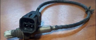
The oxygen sensor directly affects the formation of the air-fuel mixture, as well as fuel consumption. It measures the oxygen concentration in the exhaust gases, which directly controls the supply of fuel to the combustion chambers. The indicator reading varies from approximately 0.1 V (high oxygen - lean mixture) to 0.9 V (low oxygen - rich mixture).
And at the rear of the cylinder head there is a phase sensor. It determines the position of the 1st piston at top dead center. Designed and based on the action of a Hall sensor.
Another representative of air indicators is the mass air flow sensor (MAF). It is located in front of the throttle valve and with its help the amount of air that enters the combustion chamber is controlled.
This indicator analyzes the position of the throttle valve to supply and regulate the amount of air supplied to the cylinders. Usually, when the sensor fails, the amount of forced air for different engine operating modes does not change, and the power unit simply suffocates when adding the amount of fuel and revolutions.
In this case, the engine begins to stall as it gains speed, and the gasoline does not burn through in the required amount, leaving residues on the cylinder walls or flooding the spark plugs.
Additional sensors can be considered - a coolant temperature sensor located on the radiator and an electronics diagnostic sensor. These indicators are installed on cars with so-called “heavy electronics”, where all engine control processes are carried out by an on-board computer.
An integral part of the engine start control sensor is the power unit control unit. It is he who controls all the processes occurring in the engine, and also adjusts the settings for optimal starting. Failure of this element will result in the engine simply not starting.