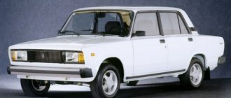
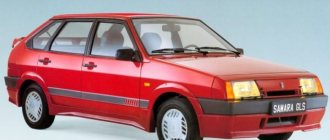
The VAZ-2112 car was produced at AvtoVAZ from 1998 to 2009, in Ukraine from 2009 to 2014. The following are color wiring diagrams (injector and carburetor) with a description of all elements for various modifications. The information is intended for self-repair of cars. Electrical circuits are divided into several blocks for ease of viewing via a computer or smartphone; there are also circuits in the form of a single picture with a description of the elements - for printing on a printer in one sheet.
To diagnose and repair yourself, first look to see if everything is okay with the generator. Is it put on well and does not sag? This procedure must be done with all versions of the fuel system, both carburetor and injection. We check the fuses according to the electrical diagram. The reverse side of the safety block cover will also be of great help. There are clues there that the diagram will help you decipher. Replace the burnt out element and try to start the car again. You need to check whether the battery terminals are tightly connected and whether they are oxidized. Is the wire going from the battery to the generator and to the starter damaged?
Modifications of the VAZ-2112 car
VAZ-21120 . Modification with a 16-valve injection engine with a volume of 1.5 liters and a power of 93 horsepower. 14-inch wheels were installed on the car. This modification has a problem with valves bending when the timing belt breaks. The problem can be solved by increasing the depth of the grooves in the piston bottoms.
VAZ-21121 . The car was equipped with a VAZ-21114 8-valve injection engine with a volume of 1.6 liters and a power of 81 horsepower.
VAZ-21122 . Budget modification with an 8-valve injection engine VAZ-2111. The car was produced without electric windows, the wheels were 13 inches in size, and the brakes were unventilated from a VAZ-2108 car.
VAZ-21123 Coupe . Three-door, five-seater hatchback. The only two doors for entering the car are 200 millimeters wider than those of the five-door hatchback, and they are mounted on new, durable hinges. The rear arches of the car have become wider. The engine was installed with a 16-valve injection engine with a volume of 1.6 liters and a power of 90 horsepower. The car was produced from 2002 to 2006 in small quantities, the reason for this was the high cost of the car.
VAZ-21124 . Modification with a 16-valve injection engine VAZ-21124 with a volume of 1.6 liters. Produced from 2004 to 2008. For this type of engine, the problem with valve bending was solved. To do this, the depth of the grooves in the piston heads was increased (up to 6.5 mm). In addition, the design of the cylinder block was changed to achieve a working volume of 1.6 liters, for which its height was increased by 2.3 mm, and the radius of the crankshaft was increased by 2.3 mm accordingly. There were also a number of other minor changes.
VAZ-21128 . The luxury version of the car, produced by Super-auto JSC, was equipped with a 16-valve VAZ-21128 engine with a volume of 1.8 liters and a power of 105 horsepower.
VAZ-2112-37 . A racing modification of the VAZ-2112, prepared for the “ring” in the Lada Cup qualifying group. The car was equipped with a 1.5-liter VAZ-2112 engine with a power of 100 horsepower. The racing car was equipped with a safety cage, an external aerodynamic kit and a front extension of the strut support cups.
VAZ-2112-90 Tarzan . All-wheel drive modification with a VAZ-2112 body on a frame chassis with transmission and suspension parts from a VAZ-21213 Niva. It was also equipped with a 1.7 or 1.8 liter engine from the Niva.
Recommendations for use
- Replace a blown fuse only with one of the same rating. Otherwise, if a larger one is installed, the equipment will not be protected from possible voltage surges. If it is smaller, then it is likely that it will burn out immediately.
- Do not use jumpers or bugs under any circumstances. Their installation can lead to equipment failure and even a fire.
- If there are malfunctions in the operation of any consumer, then pay attention and diagnose the block itself with electrical fuses.
- While operating the vehicle, be sure to diagnose all elements of the on-board network. An important part of diagnostics is checking the integrity of all wiring.
- When working with sources and electrical consumers, you must always pay attention to safety precautions, otherwise you risk injury or damage.
- Before starting work, be sure to turn off the power to the system.
Sorry, there are no surveys available at this time.
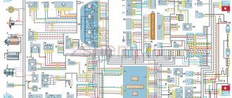
Electrical diagram of VAZ-2112
Designations: 1 – Headlight, 2 – Klaxon, 3 – Main radiator fan, 4 – Starter, 5 – Battery, 6 – Generator 2112, 7 – Gearbox limit switch (reverse), 8 – Actuator in the front passenger door, 9 – Power window enable relay, 10 – Starter relay, 11 – Heater fan, 12 – Electric heater partition drive, 13 – Main pump, 14 – Washer reservoir sensor, 15 – Driver’s door actuator, 16 – Front passenger window selector, 17 – Unlock button fifth door, 18 – Heater fan resistance unit, 19 – Main wiper motor, 20 – Driver’s window lift selector, 21 – Front passenger’s window lift motor, 22 – Central locking, 23 – Exterior light switch, 24 – Brake fluid leakage sensor, 25 – Pump additional, 26 – Driver's window lift motor, 27 – PTF on indicator, 28 – PTF switch, 29 – Dashboard, 30 – Heated glass on indicator, 31 – Heated glass switch, 32 – Steering column selector switch, 33 – PTF relay, 34 – Ignition switch, 35 – Main fuse block, 36 – Illumination of heater controls, 37 – Hazard warning button, 38 – Heater control controller, 39 – Glove compartment lighting, 40 – Glove compartment lid end cap, 41 – Cigarette lighter, 42 – BSK – display unit, 43 – Ashtray illumination, 44 – 12V socket, 45 – Instrument lighting switch, 46 – Actuator in the right rear door, 47 – Right rear passenger window selector, 48 – Clock, 49 – Right rear passenger window motor, 50 – Brake limit switch (closed – pedal is pressed), 51 – Left rear passenger window motor, 52 – Left rear passenger window selector, 53 – Actuator in the left rear door, 54 – Turn signal, 55 – Handbrake limit switch (closed – handbrake on), 56 – Rear wiper motor , 57 – Navigator's lamp, 58 – Interior lamp, 59 – Temperature sensor in the heater, 60 – Limit switch for the open front door, 61 – Limit switch for the open rear door, 62 – Trunk light, 63 – Rear optics (on the body), 64 – Rear optics (on the fifth door), 65 – License plate illumination.
The letters indicate the terminals to which it is connected: A – Front speaker on the right, B – Radio, C – Injector harness, D – ESD diagnostic connector, D – Front left speaker, E – Diagnostic connector for the heater controller, G – Rear right speaker, W – Rear left speaker, I – BC connector, K – glass heater thread, L – fifth door actuator, M – Additional brake light.
Wiring diagram VAZ-2112 injector 16 valves - full view
VAZ-21124 engine control circuit
Connection diagram of the VAZ-21124 engine control system with distributed fuel injection to Euro-2 emission standards (controller M7.9.7): 1 - ignition coils; 2 — nozzles; 3 - controller; 4 - main relay; 5 - fuse connected to the main relay; 6 — cooling system electric fan relay; 7 - fuse connected to the cooling system electric fan relay; 8 - electric fuel pump relay; 9 - fuse connected to the electric fuel pump relay; 10 — mass flow and air temperature sensor; 11 — throttle position sensor; 12 — coolant temperature sensor; 13 — solenoid valve for purge of the adsorber; 14 — oxygen sensor; 15 — knock sensor; 16 — crankshaft position sensor; 17 — idle speed regulator; 18 — immobilizer control unit; 19 — immobilizer status indicator; 20 - phase sensor; 21 — vehicle speed sensor; 22 — electric fuel pump module with fuel level sensor; 23 — oil pressure warning lamp sensor; 24 — coolant temperature indicator sensor; A - block connected to the wiring harness of the ABS cabin group; B — diagnostic block; B - block connected to the air conditioner wiring harness; G - to the “+” terminal of the battery; D — to the side door wiring harness block; E - block connected to the instrument panel wiring harness; G1, G2 - grounding points; I - the order of conditional numbering of plugs in the block of the immobilizer control unit; II - the order of conditional numbering of contacts in the diagnostic block.
Useful: VAZ 2110 diagram
Connection diagram of the VAZ-21124 engine control system with distributed fuel injection under Euro-3 toxicity standards (controller M7.9.7): 1 - ignition coils; 2 — nozzles; 3 - controller; 4 - main relay; 5 - fuse connected to the main relay; 6 — cooling system electric fan relay; 7 - fuse connected to the cooling system electric fan relay; 8 - electric fuel pump relay; 9 - fuse connected to the electric fuel pump relay; 10 — mass flow and air temperature sensor; 11 — rough road sensor; 12 — throttle position sensor; 13 — coolant temperature sensor; 14 — idle speed regulator; 15 — control oxygen sensor; 16 — diagnostic oxygen sensor; 17 — solenoid valve for purge of the adsorber; 18 — knock sensor; 19 — crankshaft position sensor; 20 — immobilizer control unit; 21 — immobilizer status indicator; 22 - phase sensor; 23 — vehicle speed sensor; 24 — electric fuel pump module with fuel level sensor; 25 — oil pressure warning lamp sensor; 26 — coolant temperature indicator sensor; A - block connected to the wiring harness of the ABS cabin group; B — diagnostic block; B - block connected to the air conditioner wiring harness; G - to the “+” terminal of the battery; D — to the side door wiring harness block; E - block connected to the instrument panel wiring harness; G1, G2 - grounding points; I - the order of conditional numbering of plugs in the block of the immobilizer control unit; II - the order of conditional numbering of contacts in the diagnostic block.
Fuel check valve
We check the ignition module on the injection 16-valve VAZ-2110
The electric fuel pump of the VAZ “Ten” has good performance, but it creates too much pressure in the fuel system. In order to bring the pressure back to normal, a VAZ 2110 fuel pump valve is built into the fuel line; it is located in the “outlet” fitting of the BN housing. On the “tens”, a pressure regulator is also installed, which is located behind the fuel rail.
A valve malfunction involves a ball sticking in the open position, and the fuel pressure in the system may drop to zero. If such a problem occurs, the car is very difficult to start, since all the gasoline from the fuel lines goes back into the gas tank when the ignition is turned off. Is it possible to somehow repair the valve?
Drivers of 2110 cars claim that you can try knocking on the fitting in the BN flask so that the shut-off ball falls into place. If the malfunction cannot be eliminated in this way, the electric fuel pump bulb must be replaced, since this housing itself is non-separable.
VAZ-2112 harness diagrams
Instrument panel harness diagram
1, 2, 3, 4 – instrument panel harness pads to the front harness; 5 — block of the instrument panel harness to the side door harness; 6, 7, 8 — instrument panel harness pads to the rear harness; 9 – rear window heating switch; 10 – light signaling switch; 11 – windshield wiper switch; 12 – block of the instrument panel harness to the radio; 13 – mounting block; 14 — instrument cluster; 15 – heater control controller; 16 – heater motor switch; 17 — block of the instrument panel harness to the ignition system harness; 18, 19 — blocks of the instrument panel harness to the air supply box harness; 20 — ignition switch; 21 – fog lamp relay; 22 – sound signal relay; 23 — power window relay; 24 — starter relay; 25 – seat heating relay; 26 – external lighting switch; 27 – fog lamp switch; 28 – cigarette lighter; 29 – lampshade lighting of the glove box; 30 – glove box lighting switch; 31 – switch for rear fog lights; 32 – right steering column switch; 33 – socket for connecting a portable lamp; 34 — instrument lighting switch; 35 – brake signal switch; 36 – sound signal switch; 37 – alarm switch; 38 – air distribution drive gearmotor; 39 – VAZ-2112 illuminator; 40 — instrument panel harness block to the front harness; 41 – trunk lock drive switch; 42 – rear fog light relay.
A – grounding point of the instrument panel harness.
Front 2112 harness diagram
Air supply box wiring diagram
VAZ-2112 heater harness diagram
Side door harness diagram
Luxury side door harness diagram
Rear Harness Diagram 2112
- common terminal block of the wiring harness for connecting the wiring coming from the instrument panel (in the diagram under No. 1);
- terminal block of the wiring harness for connection with the wiring of the instrument panel of cars in the “standard” configuration and for connection to the side door harness for cars in the “luxury” configuration (in diagram No. 2);
- rear harness terminal block for connection to the instrument panel harness (No. 3);
- two 4-pin terminal blocks (for modifications 2112-3724558-10 16 valves). Indicated on the diagram as No. 4 and No. 5;
- side direction indicators (no. 6 – left, no. 7 – right);
- power supply to the individual lighting lamp (number 8 on the diagram);
- power supply for the general interior lighting lamp (No. 9);
- handbrake sensor connector (No. 11);
- rear lights (in the diagram No. 11 is left, No. 12 is right);
- interior temperature sensor connector (No. 13 in the diagram);
- connector for connecting 4 interior dome light switches (in the diagram under numbers 14,15,16 and 17);
- connector for trunk light (No. 18);
- reserve block of the wiring harness (in diagram No. 19). Can be used as a connector to connect to the side door wiring harness;
- block for connecting the wiring harness of the license plate lights (no. 20 in the diagram);
- The wiring grounding points are indicated in the diagram as A and A1.
For the lights, tailgate and license plate lights. They are connected together and the light harness is connected to the instrument panel harness and any side door harness, from it to any additional harness (will be below) with the trunk release button. The connector with the gray wire of the light harness is connected to the instrument panel; on luxury versions, it is connected to the instrument panel through the luxury side door harness (heated mirrors are connected to it).
Ground contact
Problems with the fuel pump ground can be indicated by an incorrectly indicating fuel level sensor. Poorly secured ground can cause the fuel pump to stop pumping fuel. The ground wire is located under the dashboard and runs through the entire interior of the car. You need to find it, clean the contacts and secure it properly to the fuel pump.
Next to the ground, under the dashboard, there is a fuel pump relay. After turning on the ignition, the operating relay allows the pump to create the required pressure in the system in a few seconds, after which it turns off. When you turn the key in the ignition, you can hear a soft click, which means that the fuel pump relay is turned on, and exactly the same when it is turned off. If the relay does not make a click, then the problem is in it or in its contacts. Then it is advisable to replace it with a new one.
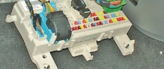
VAZ2112 fuses and relays
- F1 5 License plate lamps. Instrument lighting lamps. Side light indicator lamp. Trunk light. Left side marker lamps
- F2 7.5 Left headlight (low beam)
- F3 10 Left headlight (high beam)
- F4 10 Right fog lamp
- F5 30 Electric door window motors
- F6 15 Portable lamp
- F7 20 Electric motor of the engine cooling system fan. Sound signal
- F8 20 Rear window heating element. Relay (contacts) for turning on the heated rear window
- F9 20 Recirculation valve. Windshield and headlight cleaners and washers. Relay (coil) for turning on the rear window heating
- F10 20 Reserve
- F11 5 Right side marker lamps
- F12 7.5 Right headlight (low beam)
- F13 10 Right headlight (high beam). High beam warning lamp
- F14 10 Left fog lamp
- F15 20 Electric seat heating. Trunk lock lock
- F16 10 Relay-breaker for direction indicators and hazard warning lights (in emergency mode). Hazard warning lamp
- F17 7.5 Interior lighting lamp. Individual backlight lamp. Ignition switch illumination lamp. Brake light bulbs. Clock (or trip computer)
- F18 25 Glove box lighting lamp. Heater controller. Cigarette lighter
- F19 10 Door locking. Relay for monitoring the health of brake light lamps and side lights. Direction indicators with warning lamps. Reversing lamps. Generator excitation winding. On-board control system display unit. Instrument cluster. Clock (or trip computer)
- F20 7.5 Rear fog lamps VAZ-2112.
- K1 – lamp health monitoring relay;
- K2 – windshield wiper relay;
- K3 – relay-interrupter for direction indicators and hazard warning lights;
- K4 – headlight low beam relay;
- K5 – headlight high beam relay;
- K6 – additional relay;
- K7 – relay for turning on the heated rear window;
- K8 – backup car relay.
Main settings
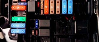
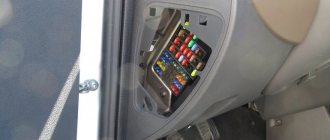
The fuse box is located under the decorative panel to the left of the steering column. Removing it is quite simple: press the latch and lower the structure down. Once you have access to the fuses, they can be removed and checked for integrity using a millimeter. The block contains only 20 fuses, designed for different current strengths.
Just look at the color of the fuse to determine what amperage it is designed for:
- tan runs at 5 amps;
- darker brown – at 7.5;
- red – at current strength 10;
- saturated blue – at 15;
- bright yellow is for 20;
- colorless or transparent – by 25;
- green – by 30.
Remember that you cannot install a stronger fuse element, and you should also not swap fuses. If the current strength is not observed, the protected unit may fail. If you do not have the necessary knowledge, entrust work with the electrical part of the board to a professional. To protect yourself from a car fire, do not install a wire in place of a failed fuse, as this will lead to a short circuit.
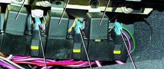
Behind the main unit you can notice separately connected devices, one of them protects the fog lights, and the second protects the central locking. Older cars do not have additional fuses protecting the car radio and alarm system.
If you equip your car with additional equipment, be sure to include these items.
Introduction.
Have you checked the fuses? Isn’t this the phrase we hear most often from our comrades and repair advisors? Indeed, the VAZ 2110 fuse box protects each of the key elements of the electrical circuit and it is very worth checking them. But when is it really useful, and when can it be considered just a waste of time?
It doesn’t matter which element of the car has failed: it could well be a broken starter, dead wipers or headlights, for example. Checking the protection circuit is the fastest and most effective way and the easiest way to start repairs. But if the fuses in your car “like” to blow out often, are they really needed? Is it possible to refuse unwanted “protectors”?
But if the fuses in your car “like” to blow out often, are they really needed? Is it possible to refuse unwanted “protectors”?
In the inquisitive mind of a motorist, many specific questions arise regarding the maintenance and repair of his iron horse. Quite tricky in some places, very interesting in others. Even about the usual VAZ-2110 safety block you can write a lot of useful information. Perhaps you didn’t know something or were embarrassed to ask. We tried to answer various useful questions in this thematic article.
What fuses are included in the block?
In total, the block contains 20 elements. The number scheme looks like this:
- F1 protects the power circuit of the license plate lighting lamps, instruments, trunk and left side dimensions, as well as the control light indicating the operation of the side dimensions;
- F2 is responsible for the low beam of the left headlights;
- F3 – for high beam headlights on the left side;
- F4 works in conjunction with the right fog lamp;
- F5 protects electric window motors from overload;
- F6 is in the portable lamp circuit;
- F7 is responsible for protecting the horn and the cooling system fan of the power unit;
- F8 – for relay contacts and elements of the rear window heating system;
- F9 – for the relay coil for turning on the heated rear window, recirculation valve, windshield and headlight washers, as well as for their cleaners;
- F10 is in reserve;
- F11 protects the chain of dimensions located on the right;
- F12 is responsible for the functionality of the low beam of the right headlights;
- F13 – for the functionality of the high beam headlights on the right and the indicator light notifying that this type of lighting is turned on;
- F14 is in the circuit with the left fog lamp;
- F15 protects the luggage compartment lock and heated seats;
- F16 works with hazard warning lamps and turn signal breaker relay;
- F17 is responsible for the brake light and interior lighting lamps located near the clock or on-board computer screen, at the ignition switch, in the individual lighting circuit and on the ceiling;
- F18 – for glove compartment lighting, cigarette lighter and heater controller;
- F19 - for the control relay of the stop signal and side lights, locking, turn indicator lamps, on-board control system indication, clock or computer, generator winding and instrument cluster.
- F20 – for rear fog lights.
The rated current is determined by the color of the fuse. As you can see, most elements are part of a chain of several nodes.
MB types
It is worth noting that the pinout of fuses for the VAZ “Ten” is somewhat different, depending on the revision. The location of the backup protection relay varies greatly.
Version 3722010
Version 3722010 01
Version 3722010 08
The article was written with the support of our partners in Minsk - unishop.by. Here you can buy household dehumidifiers of various types, of excellent quality and at a reasonable price. unishop.by is a large shopping portal where you can find the right product at a good price, easier and faster.
Electromagnetic relays
To relieve the car switch contacts from high current consumption, electromagnetic relays are used in the electrical circuit. There are 8 of them in total:
- K1 is responsible for the serviceability of the lamps;
- for turning on the front window wiper - K2;
- for turn signals and hazard warning lights – K3;
- for low beam headlights - K4;
- for turning on the high beam - K5;
- for heating the rear window - K7;
- for fog lights located at the rear - K8.
The block contains relay K6, which is additional. Before installing a new element into the system, check the wiring for short circuits, otherwise the parting that is protected by the fuse element or the fuse itself may fail. The described block is the main one, but the only one in the VAZ-2112 electrical circuit.
Sources
- ladaautos.ru/vaz-2112/raspinovka-bloka-predoxranitelej-vaz-2112-inzhektor-16-klapanov.html
- 2shemi.ru/shema-vaz-2112/
- vazdriver.ru/blok_predohraniteley_vaz2110/shema_i_raspolozhenie_predohraniteley_vaz_2110_2111_2112.html
- drive2.ru/l/2251582/
Replacement example
Since all fuses are located in a common block, the replacement principle is the same for all. Therefore, we can consider an example of only one element that needs replacement. Let this be the cigarette lighter. It is designated F6 and F18 (see table).
The first priority before replacing a fuse is to check its functionality. Many people immediately change the element without even considering whether the problem of the unit failure really lies in it.
Remove with tweezers
To check the fuse, you should perform several step-by-step operations:
- Start the car by turning the key in the ignition;
- Make sure that the cigarette lighter is inside its socket, where it should be;
- Wait about 20 seconds;
- Take out the cigarette lighter and check if it is warm. If the temperature remains the same, that is, the element is cold, then the fuse needs to be changed.
How to do it? Pretty easy.
- Get to the panel on which the board with the relays and cigarette lighters is located. The mounting block is located, as you remember, to the left of the steering wheel, at the bottom of the dashboard.
- By pressing the special latches, the cover will move away from its seat. Be careful not to break the latches.
- The mounting block has now opened in front of you.
- If you look at it carefully, you will see special tweezers on the edge. It is provided by the factory in order to carefully remove fuses and insert new elements in their place.
- Remove the affected fuse. In this particular situation, we are talking about the cigarette lighter fuse, so you need an element designated F6 or F18.
- This component burns out due to the fact that modern motorists need additional electrical equipment, such as vacuum cleaners and electric pumps. All this is connected to the fuse and overloads it. Hence the frequent breakdowns.
- Using the same tweezers, insert a new fuse with the same parameters indicated on the mounting block.
If for some reason you don't have tweezers inside your black box, small pliers can serve as an alternative to this tool. Never try to remove the elements with your fingers. The nests are quite fragile, and with your hands you can only loosen it and damage it.
Replacing relays and fuses is a simple and inexpensive repair. But if you damage the block itself, then you will have to spend more, and you will definitely have to work hard.
Are fuses repairable? No. These are fusible elements that simply become deformed when burned. Therefore, repair is possible only in one option - replacing blown fuses.
There are times when, for no apparent reason, the windshield wipers stop functioning, the rear and front turn lights do not turn on, the fuel pump does not turn on, or the cigarette lighter coil simply does not heat up. In this case, do not rush to run to the store to buy a brush motor or spend money on light bulbs or other devices. Most likely, it's all about blown fuses or relays. You need to carefully study the fuse block diagram of the VAZ 2110 and then you can easily fix this problem.
All electrical consumers in a car are protected by small and very simple devices - fuses. In particular, thanks to these simple devices, in the event of an increase in voltage, the wiring will not burn out, but the circuit will simply break. Each electrical fuse or relay is designed for a specific amperage and has an individual purpose. In some cases, one fuse controls several devices, for example, a cigarette lighter and other equipment.