Clutch master cylinder operation
The clutch master cylinder works as follows. When you press pedal 21, pusher 14 moves piston 4, compressing spring 8.
As soon as the cuff 10 closes the bypass hole b, pressure is created inside the cylinder in cavity a, and the liquid passes through the hole in the fitting 7 and through the connecting tube 2 into the working cylinder 29, causing the movement of the piston 36, the pusher 27 and connected to it through the tip 24 and pin 23 forks 22 clutch release. The clutch disengages. At the same time, the tension spring 25 of the fork is stretched and the pressure springs 14 are compressed.
We recommend: Removing the selector of an automatic transmission of a car (automatic transmission)
When the clutch pedal is released, the latter returns to its original position by spring 75, and the piston 12 of the master cylinder, under the action of the return spring 8, moves after the pusher 17 until it stops against the washer 14. At the same time, the pressure in the system drops, and the clutch pressure plate changes under the action of the pressure springs , presses the driven disk against the flywheel again. The clutch engages. Moving the pressure plate until it stops against the driven disk causes the heel associated with it to move through the release levers and the thrust bearing resting against it.
Next, the thrust bearing and the associated clutch release fork move under the action of the tension spring 25, which constantly presses the pusher rod 27 against the piston 36 and moves the latter to its extreme forward position. In this case, the piston displaces liquid from the internal cavity of the working cylinder 29. The liquid through tube 2 returns to cavity a of the main cylinder.
When the clutch pedal is abruptly released, the fluid returning from the working cylinder to the main cylinder does not have time to fill the space vacated by piston 12, and a vacuum is created in cavity a.
Under the influence of this vacuum, liquid from cavity e (where it enters through hole c) flows into cavity a through holes d in the piston head, pushing back valve 11 and the edges of cuff 10. Grooves on the surface of cuff 10 facilitate the passage of liquid from cavity d to cavity a. Subsequently, excess fluid, as it enters from the pipeline, is forced out of cavity a through the compensation hole b into tank 3. The flow of fluid from the connecting tube into the clutch master cylinder stops as soon as the piston of the working cylinder, under the action of the pressure springs and the release spring of the clutch release fork, returns to extreme forward position.
Clutch release drive device
The stamped clutch pedal 21 is mounted on a welded bracket 12, fixed to the body with bolts 11 and studs 8 with nuts 7. The clutch pedal swings on an axis 16, which is fixedly fixed in the bracket 12. The pedal is secured against rotation by a flat that fits into a shaped hole in one of the cheeks pedal bracket.
The axial movement of the axis is limited by the cotter pin 13 and the shoulder of the flat. Two polyamide bushings 17 rotating on an axis, having collars at one of the ends, are inserted into the pedal hub.
The bushings have high wear resistance and do not require lubrication during operation. A rubber pad 31 is put on the pedal platform. The pedal is held in its original (rearmost) position by the force of the tension spring 15. In this case, the non-adjustable pusher 14, pivotally connected to the pedal with a pin 19, rests against the limiting washer 5, fixed in the axial direction with a locking ring.
In the initial position of the pedal, the piston 12 of the clutch master cylinder under the action of the spring 8 abuts its end against the washer 14. Between the pusher 14 and the piston 4 there is a constant gap of a = 0.2 - 1.0 mm, which is ensured within the specified limits by the selected dimensions of these parts and the limiting washers 5.
We recommend: Clutch slave cylinder: repair or replacement?
The specified gap provides the piston of the master cylinder with the opportunity to take its original position (with the clutch engaged), guaranteeing communication between cavity a of the cylinder and the filling tank 3 through compensation hole b.
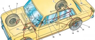
In clutch and foot brake control drives, pedal axles, polyamide bushings, pushers, pedal linings and fasteners are interchangeable. The clutch master cylinder is designed to create pressure in the hydraulic clutch drive system. The cylinder has a cast iron body 9 with an internal diameter of 22 mm with a figured flange; Two pins 18 are screwed into the flange, with the help of which the cylinder and pedal bracket 12 are attached to the front panel of the body. During assembly, up to four (as needed) adjusting shims 6, made of sheet steel 0.5 mm thick each, are installed between the cylinder body flange and the front body shield. These spacers help establish the initial position of the clutch pedal, which should ensure its full travel L until it touches the rubber floor mat, equal to 150-155 mm.
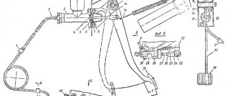
Rice. Clutch release drive: 1 — bracket for fastening the connecting tube; 2 — connecting tube; 3 — clutch master cylinder assembly; 4 — piston of the clutch master cylinder; 5 — limit washer; 6 — adjusting gasket; 7 and 28 - nuts; 8 — master cylinder mounting pin; 9 — supply tank for the clutch master cylinder; 10 — nut holder; 11 — bolt of fastening of the clutch pedal bracket; 12 — clutch pedal bracket: 13 — cotter pin for the clutch pedal axis; 14 — piston pusher of the clutch master cylinder; 15 — clutch pedal release spring; 16 — axis of the clutch and brake pedals; 17 — bushing for the clutch and brake pedal axle; 18 and 33 - washers; 19 and 23 - fingers; 20 and 32 — cotter pins; 21 — clutch pedal; 22 — clutch release fork; 24 — pusher tip; 26 — release spring for clutch release fork; 26 - lock nut; 27 — fork pusher; 29 — clutch operating cylinder; 30 — pin for fastening the working cylinder; 31 — pedal pad; 34 — protective cap; 35 — retaining ring; 36 — piston of the working cylinder; 37 — sealing collar; 38 — spacer mushroom; 39 — spring; 40 — air release valve; 41 — valve protective cap; 42 — tube fastening bracket; 43 — gasket
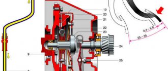
At the top of the master cylinder body there is a tank 3 made of translucent plastic. The reservoir contains a certain supply of brake fluid necessary for the normal operation of the hydraulic clutch drive. The tank is closed with a plastic threaded cap 1, in which there is a hole to communicate the internal cavity of the tank with the atmosphere, and a reflective plate is attached to prevent the brake fluid from splashing out through the specified hole. The flange of the strainer 2 rests on the end of the supply tank, which simultaneously functions as a damper for the brake fluid in the tank.
The nutrient tank 3 is attached to the main cylinder body 9 with a threaded fitting 4, which has a slot at the end for a screwdriver. The sealing gasket 5 after tightening the fitting guarantees the tightness of the connection between the tank and the cylinder body. Through the hole in fitting 4, brake fluid from reservoir 3 flows by gravity into housing 9 of the master cylinder.
A rubber sealing collar 13 is placed on the piston 12 located inside the cylinder, which prevents liquid from leaking out of the cylinder. The piston is cast from zinc alloy. There are six through holes in the piston head, covered with a thin steel ring-valve 11 and an internal working rubber cuff 10. On the outer surface of the cuff there is one annular and six longitudinal grooves. Spring 8 presses the cuff against piston 12, and the piston against thrust washer 14. The other end of the spring rests against threaded fitting 7, which closes the internal cavity of the cylinder body.
A rubber protective cap 16 protects the internal cavity of the cylinder from dust. The cap is tightly placed on the groove in the cylinder body and the pusher rod 17.
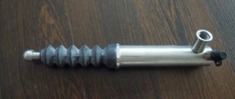
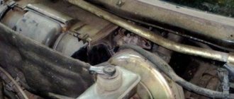
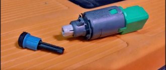
The clutch slave cylinder 29 is secured with two studs 30 and nuts 28 on the left side of the clutch housing. The internal diameter of the working cylinder is 22 mm.
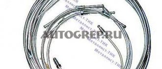
The main and working cylinders are connected to each other by a bent copper (6×1 mm) or two-layer steel tube 2 with copper-plated inner and outer surfaces (6×0.7 mm). The spiral located in the middle part of the tube compensates for the change in the distance between the ends of the tube, which is inevitable when the position of the power unit, suspended on rubber cushions, changes relative to the body. In addition to being secured at the ends, the tube has two intermediate attachment points: on the left mudguard of the body using bracket 1 and on the engine crankcase using bracket 42. Rubber gaskets 43 are laid between the fastener and the tube. The ends of the tube have a double conical flaring, the shape and dimensions of which shown in the figure. Before flaring the ends, connecting nuts are put on the tube, with which it is then connected to the main and working cylinders.
Rice. Clutch master cylinder: 1 — reservoir cap; 2 - mesh filter; 3 - tank; 4 — tank fitting; 5 — tank fitting gasket; 6 — master cylinder fitting gasket; 7 — main cylinder fitting; 8 - spring; 9 — main cylinder body; 10 — sealing collar of the main cylinder; 11 — piston valve; 12 - piston; 13 - piston seal; 14 - thrust washer; 15 — retaining ring; 16 — protective cap; 17 — piston pusher; 18 — master cylinder mounting pin
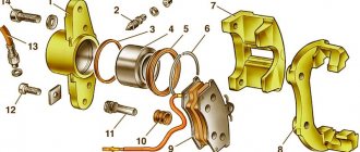
The housing 3 of the working cylinder is a casting made of gray cast iron, having on one side an open cylindrical cavity into which a cast aluminum piston 7 with a rubber sealing collar b, a spacer fungus 5 and a spring 4 are inserted. The spring constantly presses the spherical surface of the fungus against the sealing edge of the cuff and through it the edge to the cylinder mirror, which significantly improves the seal of the working cylinder, especially when there is no pressure in the system (the clutch is engaged).
Rice. Flaring the ends of the connecting tube (tube cross-sectional dimensions: steel - 6 X 0.7; copper 6 X 1.0)
Rice. Clutch slave cylinder: 1 — valve protective cap; 2 — air release valve; 3 - cylinder body; 4 - spring; 5 — spacer fungus; 6 - sealing collar; 7 - piston; 6 — protective cover; 7 - retaining ring
The conical valve 2 screwed into the cylinder body 3 serves to remove air from the hydraulic drive system. Rubber cap 1 is placed on the valve head and protects the internal channel of the valve from clogging.
We recommend: Replacing the ignition switch contact group in 6 steps
A pusher 27 is inserted into the spherical recess of the piston 36, which is adjustable in length. The pusher is adjusted by screwing it in or out of the fork tip 24. The position of the tip is fixed by the lock nut 26. The spring 25 of the clutch release fork 22 constantly presses the pusher to the spherical surface of the piston and, in the absence of pressure in the clutch hydraulic drive system, moves the piston to the extreme forward position. Since the piston 36 in the cylinder 29 can move in the direction corresponding to the clutch disengagement (to the right in the figure) only under the influence of the working fluid pressure, the formation of vacuum is eliminated, and therefore the penetration of air into the cylinder through leaks in the piston. Therefore, there is no need to maintain excess pressure in the connecting tube 2 and in front of the piston 36, which is usually provided by installing a double valve in the master cylinder, as is done in the hydraulic brake drive (see below). All parts of the clutch master cylinder, with the exception of housing 9 and fitting 7, are interchangeable with the corresponding parts of the brake master cylinder. Since the clutch master cylinder does not have a double valve, the body and fitting of this cylinder are different from the body and fitting of the brake master cylinder. To make it easier to distinguish between the clutch and brake master cylinders, their mounting flanges are rotated 60° relative to each other. A protective rubber cover 8 protects the internal cavity of the working cylinder from dirt.
Hydraulic drive device
With this constructive solution, the force is transmitted in a different way. The hydraulic drive circuit does not require a cable; the implementation of a mechanism with this type of control is a little more complicated and the cable is replaced by a hydraulic line. The force is transmitted through an incompressible fluid passing through the line, and since the hydraulic drive is similar to that used in the brake system, the same fluid is used for operation. The clutch device, controlled by a hydraulic drive, includes the following elements:
- Pedal.
- The main cylinder, consisting of a piston with a pusher, a fluid reservoir and sealing collars.
- The slave cylinder has a similar design.
- The line connecting the cylinders.
- Liquid reservoir.
- Additionally, the cylinders are equipped with valves to remove air from the system.
The principle of operation is quite simple and similar to the mechanical control option, the only difference is in the method of transmitting force. When a motorist presses the foot lever inside the car, the piston of the master cylinder is set in motion, the fluid is compressed and, under pressure, moves through the pipeline into the slave cylinder, pushing the piston, which engages the clutch release fork.
The hydraulic drive can also be equipped with a damping device to dampen vibrations from the interaction of the release bearing with the clutch release parts. Pneumatic or hydraulic boosters are often used for commercial vehicles.
Since a hydraulically driven mechanism is a more advanced and complex device that transmits force over a long distance with high efficiency, its cost is higher, and it is characterized by smooth clutch engagement, which is due to the resistance to fluid movement in the structural elements. Among the advantages of a hydraulic drive is also resistance to wear of parts, but repairs are also more difficult than in the case of a mechanical device.
Mechanical and hydraulic drives are endowed with their own operating features, pros and cons of application, while devices of these types provide comfort in driving a vehicle. In passenger cars, the stiffness of the diaphragm spring of the pressure plate is small, so the driver does not need to exert much effort, but on trucks the unit is larger, and in order to operate the basket, more effort is required from the driver, so amplifiers are introduced into the design.
At the end of the procedure, the clutch pedal should work normally, and there should be no problems with the pistons. This is extremely important, since in some cases swelling of various rubber elements can occur, which is very dangerous because it leads to failure of the entire system.