Earbuds
No adjustment operations should be performed on the liners. If there are scuffs, marks or peeling, replace the liners with new ones.
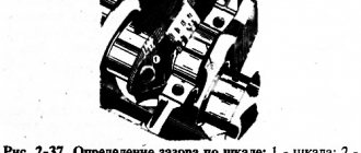
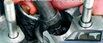
The gap between the liners and the crankshaft journals is checked by calculation (by measuring the parts). It is convenient to use a calibrated plastic wire to check the gap. In this case, the verification method is as follows:
- thoroughly clean the working surfaces of the liners and the corresponding neck and place a piece of plastic wire on its surface;
- Install a connecting rod with a cap or a main bearing cap on the journal (depending on the type of journal being tested) and tighten the fastening nuts or bolts. Tighten the connecting rod bolt nuts to a torque of 51 Nm (5.2 kgf m), and the main bearing cap bolts to a torque of 80.4 Nm (8.2 kgf m);
- remove the cover and use the scale on the package to determine the size of the gap by flattening the wire (Fig. 2-38).
The nominal design clearance is 0.02-0.07 mm for connecting rods and 0.026-0.073 mm for main journals. If the gap is less than the limit (0.1 mm for connecting rods and 0.15 mm for main journals), then these liners can be used again.
If the gap is greater than the limit, replace the liners on these necks with new ones.
If the crankshaft journals are worn and ground to repair size, then replace the bearings with repair bearings (of increased thickness).
Disadvantages of the VAZ 21214 engine
The disadvantages of the base VAZ 21213 engine are complemented by:
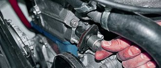
Frequent manufacturing defects (defects) of hydraulic supports of valve levers (hydraulic compensators). Due to the low level of technological discipline and technical control at the enterprises of manufacturers of precision pairs for hydraulic mounts, parts are produced with a high number of defects, and when assembling heads at the parent enterprise (machining tolerances are not maintained, foreign objects are present, the clamping of the plunger in the hydraulic mount housing results in non-compliance with the tightening torque when installing into the head). For this reason, if the hydraulic mounts wear out, you have to install a new head complete with hydraulic mounts.
Also interesting: What to check when buying a Niva
The latest engine modifications are equipped with time-tested hydraulic valve lever mounts from INA. From them we can say for sure that the risk of deformation of the housing during tightening is reduced to zero. The photo below shows a new type of hydraulic support (with M 24×1.5 thread) in detail (body, plunger) and in assembly.
Low service life before major overhaul. Saving on the quality of the materials used, along with the unreliability of components, parts and assembly units, negatively affects the reliability of the motor and its service life.
PS Dear car owners! What weak points and shortcomings did you encounter with this engine?
Thrust half rings
Just like on the liners, no adjustment operations can be performed on the half rings. If there are burrs, marks or peeling, replace the half rings with new ones.
Half rings are also replaced if the axial clearance of the crankshaft exceeds the maximum permissible - 0.35 mm. Select new half rings with a nominal thickness or increased by 0.127 mm to obtain an axial clearance in the range of 0.06-0.26 mm.
The axial clearance of the crankshaft is checked using an indicator, as described in the chapter “Engine Assembly” (Fig. 2-14).
The crankshaft axial clearance can also be checked with the engine installed in the vehicle. In this case, the axial movement of the crankshaft is created by pressing and releasing the clutch pedal, and the amount of clearance is determined by the movement of the front end of the crankshaft.
Main and connecting rod journals
Examination.
Install the crankshaft on two prisms (Fig. 2-36) and check with an indicator:
- main journal runout: maximum permissible 0.03 mm;
- runout of the seating surfaces under the sprocket and gearbox input shaft bearing; maximum permissible 0.04 mm;
- displacement of the axes of the connecting rod journals from the plane passing through the axes of the connecting rod and main journals; maximum permissible ±0.35 mm;
- non-perpendicularity of the end surface of the flange with respect to the axis of the crankshaft. When turning the shaft, the indicator installed on the side, at a distance of 34 mm (Fig. 2-36) from the shaft axis, should not show a runout of more than 0.025 mm.
Rice. 2-36. Permissible runout of the main surfaces of the crankshaft
Cracks are not allowed on the main journals, connecting rod journals and on the crankshaft cheeks. If they are found, replace the shaft.
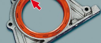
Scratches, nicks and risks are not allowed on the surfaces of the crankshaft mating with the working edges of the oil seals.
Measure the diameters of the main and connecting rod journals. The journals should be ground if their wear is more than 0.03 mm or the ovality of the journals is more than 0.003 mm, and also if there are burrs and marks on the journals.
Grinding of necks.
Grind the main and connecting rod journals, reducing by 0.25 mm, so that, depending on the degree of wear, you obtain diameters corresponding to the values given in the table. 2-2, 2-3 and neck fillet radii, as shown in Fig. 2-35.
After grinding and subsequent finishing of the journals, rinse the log shaft thoroughly to remove any remaining abrasive. Rinse the lubrication channels with the plugs removed several times with gasoline under pressure. On the first cheek of the crankshaft, mark the amount of reduction of the main and connecting rod journals (for example, K 0.25; W 0.50). The ovality and taper of the main and connecting rod journals after grinding should be no more than 0.007 mm.
Product added to bookmarks!
- Description
- Reviews
Standard crankshaft from the VAZ 2130 1.8L engine (OPP VAZ).
A crankshaft with a stroke of 84 mm (cast iron) is installed in the VAZ 21213 (Niva) and VAZ 2123 (Niva-Chevrolet, CHEVROLET NIVA) block together with
TDMK pistons (82.0 mm - 82.4 mm - 82.8 mm - 84.0 mm), with standard or lightweight connecting rods.
This crankshaft can be installed in the block of a VAZ 2103 (1.5L) and VAZ 2106 (1.6L) without replacing connecting rods and pistons (an accurate calculation of the compression ratio and adjustment of the combustion chamber will be required).
You can increase the engine displacement by: replacing the crankshaft with another one with a larger stroke, increasing the cylinder diameter, or both at the same time. We must not forget that when changing engine volume, it is necessary to increase the volume of the combustion chamber - to compensate for the increase in cylinder volume.
When installing a crankshaft with a long stroke, it is necessary to replace the pistons.
Boring the block cylinders by a significant amount (2 mm) must be approached with caution. For example, when a serial VAZ 21083 block is bored from 82 mm to 84 mm, the engine experiences increased oil consumption. This occurs due to the loss of block rigidity. In this case, it is better to use a special thick-walled block casting. VAZ produces such blocks in small batches.
An increase in engine displacement leads to an increase in maximum torque , but at the same time there is a decrease in maximum power speed. This is due to a decrease in mechanical efficiency. If the increase in volume occurs due to an increase in the diameter of the cylinders, then the contact area between the cylinder walls and the piston with piston rings increases. As a result, friction increases. If the increase in volume occurs due to an increase in the crankshaft stroke, then the average piston speed increases, which leads to the same results.
In any case, an increase in volume leads to a drop in the overall efficiency of the engine.
VAZ engine volume (in cubic cm) depending on the cylinder diameter and piston stroke.
Diameter Stroke, mm cylinder, 80 84 86 88 mm 76.0 1451 1524 1560 1596 76.4 1466 1540 1576 1613 76.8 1476 1556 1593 1630 79.0 1568 1646 1685 17 25 79.4 1584 1663 1702 1742 79.8 1600 1680 1720 1760 80.0 1608 1688 1628 1768 82.0 1689 1774 1816 1858 82.4 1706 1791 1834 1876 82.8 1722 1808 1851 1894 84, 0 1772 1861 1905 1950
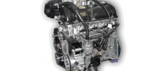
Description of the motor device 21213
The basis of the VAZ 21213 engine includes:
- cast iron cylinder block (BC) 21213-1002011;
- block head 21213-100301*;
- crankshaft 21213-1005015;
- connecting rod and piston group 21213-10040*.
The main difference between the 21213 engine and its predecessors was the increased cylinder diameter - 82 mm versus 76 and 79 mm. The center-to-center distance of 95 mm remains the same, and allows the block to be bored to a diameter of 82.8 mm. The design of the water jacket has changed. The working volume has increased by 100 cm3, but the engine dimensions have remained the same.
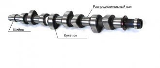
To install the crankshaft in the BC there are 5 supports: one each on the front and rear walls, 3 more on the ebb. The crankshaft parameters provide a piston stroke of 80 mm. The crankshaft is cast from cast iron and consists of 4 connecting rods and 5 main journals. The connecting rod journals have oil channels. The necks are separated by cheeks with counterweights. In previous VAZ engines, balancing counterweights were found only in the outer and central cheeks. The axial movement of the shaft is limited by thrust half-rings.
The piston group for the 21213 engine was developed anew. Pistons 21213-1004015 are cast from aluminum and reduced to a single mass of 347 g. The piston class (A, B, C, D, E) is determined by the outer diameter in increments of 0.01 mm. The shape of the piston is conical in height and oval in cross section. The hole for the pin is 22 mm, offset by 1.2 mm from the piston axis. The finger is locked with rings. There are 3 rings installed on the piston skirt:
- upper compression barrel;
- medium oil scraper with expansion coil spring;
- lower compression scraper type.
The connecting rod 21213-1004045 is forged from steel and processed together with the cover. A steel-bronze bushing is pressed into the upper head of the connecting rod. To fasten the connecting rod, M9x1.0x56 bolts are used.
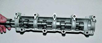
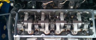
The aluminum BC head is designed for the VAZ 21213 engine and is designed for compression from 10 bar. Installing a head from other motors may cause it to break. Cast iron seats and guide bushings for 4 intake and 4 exhaust valves are pressed into the head. The valves operate from the camshaft cams. The gap between the valve stem and the cam is adjusted with a bolt.
Similar article VAZ 21126 engine, technical characteristics of the engine
timing belt
The camshaft 21213-1006010 is made of cast iron and rests on 5 journals. The jaws are bleached to increase wear resistance. Axial movement of the shaft is limited by a thrust flange.
The timing belt is driven by a double-row bush-roller chain. In addition to the camshaft, the chain drives the oil pump. The drive is regulated by a semi-automatic tensioner with a shoe and damper. To prevent the chain from falling off when removing the camshaft sprocket, a limiter is provided next to the crankshaft drive sprocket.
Systems
The power supply system in the Niva 21213 engine is a 21073 Solers carburetor. The carburetor unit is two-chamber, the throttle valves operate sequentially. When the first chamber is 2/3 open, the throttle of the second chamber is engaged. At idle, the economizer turns on. The carburetor device includes:
- float chamber;
- 2 dosing systems;
- crankcase gas suction system;
- heating the throttle zone of the first chamber;
- blocking the second camera;
- economizer;
- econostat;
- diaphragm accelerator pump.
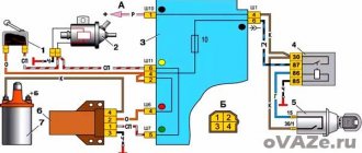
The ignition system in the 21213 engine is non-contact. The system is controlled by a switch using distributor signals. In general, the system is classic, without any special features.
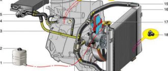
Cooling of the motor occurs according to a typical scheme: liquid circulates through the water jacket in the BC and the block head. The pressure is created by a centrifugal pump connected by a belt drive to the crankshaft and generator. The radiator fan impeller works on suction, so in winter the radiator has to be covered with cardboard.