Every modern car owner knows about the existence of an on-board computer, which can not only indicate the basic parameters of the operating mode (speed, consumption, temperature), but also recognize errors caused by various malfunctions. Unfortunately, Chevrolet Niva error codes cannot be deciphered without additional tables, since there are too many of them. Let's consider various diagnostic methods.
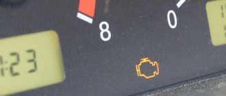
We receive the first signal about the presence of a malfunction using the indicator on the “Check-Engene” panel.
After turning on the ignition, all systems are tested, and if no errors are detected, this indicator goes out. Otherwise it remains burning. Specialized centers will quickly identify the error and not for free, but the Chevrolet Niva has a built-in on-board computer that can allow you to deal with the problem yourself.
Self-diagnosis
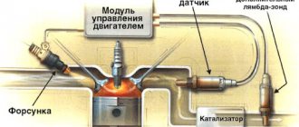
Without going into details of the operation of all electronics, we note that the functioning of all vehicle systems is “monitored” by an electronic control unit (ECU).
It receives information from numerous sensors. Like any computer, the ECU requires software called firmware. This firmware is capable of analyzing indicators received from sensors, comparing them with normal parameters, identifying errors and storing these errors in memory.
Carrying out self-diagnosis
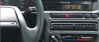
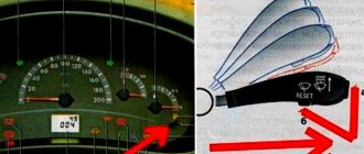
In the Chevrolet Niva, as in some other cars of the VAZ family, some parameters can be displayed on the VDO dashboard. It is often called an integrated on-board computer.
Testing is started by first pressing the daily mileage reset button and simultaneously turning the ignition key.
All instrument needles begin to move, which indicates the beginning of the testing process. Pressing the same button once will cause the firmware version to appear on the display, and pressing it again will give us a reading called an error code.
Panel codes should not be confused with ECU codes, which are diagnosed by external devices.
| Error code | Decoding |
| 1 | Processor faults |
| 2 | No signal from the fuel level sensor |
| 4 | Increased voltage of the on-board network (exceeds 16 V) |
| 8 | Reduced voltage on-board network |
| 12 | Control indicator malfunction |
| 13 | No signal LAMDA probe |
| 14 | Increased coolant temperature |
| 5 | Reduced coolant temperature |
| 19 | Error from HF sensor |
| 21-22 | Error with TPS |
| 24 | Error from speed sensor |
| 27 — 28 | Incorrect CO potentiometer parameters |
| 23 — 25 | Error from intake air temperature sensor |
| 33 — 34 | Error from the MAF sensor |
| 35 | Error from sensor XX |
| 41 | Error from phase sensor |
| 42 | Ignition system malfunction |
| 43 | Error from knock sensor |
| 44 — 45 | Rich/lean fuel mixture |
| 49 | Loss of vacuum |
| 51 — 52 | ROM/RAM errors |
| 53 | No signal from CO potentiometer |
| 54 | No signal from the octane corrector |
| 55 | Load on the power unit |
The operation of the on-board computer cannot be called flawless, since many errors arise as a result of software failure. You have to reset the errors by holding down the daily mileage reset button in testing mode. This diagnostic method is not entirely convenient for the reason that the error code can be the result of the sum of two codes at the same time (10=8+2).
Diagnostics with a scanner
The information in this section is quite extensive, since there are many types of scanners.
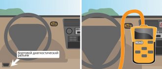
The basic principle of their operation is that all data, including errors, is transmitted from the ECU to a special diagnostic connector, which in a Chevrolet Niva is located on the driver's side under the steering wheel.
The scanner's job is to read and decode these messages.
Note that there are dealer scanners, that is, those that are designed for a given car. For Chevrolet Niva this is BC State.
It is inserted into the panel instead of the signaling device, and the information loop is prepared from the factory.
Universal scanners should be connected to the diagnostic connector. The most popular scanners today are models that allow you to transmit information via Bluetooth.
To do this, you need to install the appropriate application on your smartphone, for example, OpenDiag, and connect it to the scanner.
The program interface allows you not only to read the parameters, but also to manage some of them. You can also reset all errors from your smartphone. There are scanners with their own display. All error information in the form of codes is displayed on this display.
Error P1602
P1602 (Court Controller, Power Loss) is another common Chevrolet Niva error.
Code P1602 is entered if the following conditions are met:
- ignition on;
- The controller has detected a loss of RAM data.
The codes should be cleared using a scan tool. If the code is entered again, check the power supply circuit from the battery to pin “12” of the controller.
What errors have you encountered on Chevrolet Niva? You will find other reference information on ChevyNiva here.
Keywords: Niva on-board computer | Niva engine | esud niva
+2
Share on social networks:
Found an error? Select it and press Ctrl+Enter..
Chevrolet Niva error codes
Errors transmitted through the diagnostic connector are displayed on an external device as a four-digit code. There are special tables that allow you to decipher these codes.
| Code | Explanation |
| P0102 | Low signal level of the mass air flow sensor (MAF). |
| P0103 | High signal level of the mass air flow sensor (MAF). |
| P0112 | low signal level of the intake manifold temperature sensor (ITM). |
| P0113 | High signal level of the intake manifold temperature sensor (IMT). |
| P0116 | The signal from the coolant temperature sensor (TTOZH) is out of the permissible range. |
| P0117 | Low signal level of the coolant temperature sensor (DTOZH). |
| P0118 | High signal level of the coolant temperature sensor (DTOZH). |
| P0122 | Low signal level of the throttle position sensor (TPS). |
| P0123 | High signal level of the throttle position sensor (TPS). |
| P0130 | Incorrect signal from oxygen sensor No. 1 to the converter. |
| P0131 | Low level signal from oxygen sensor No. 1 to the converter. |
| P0132 | High level signal from oxygen sensor No. 1 to the converter. |
| P0133 | Slow response to enrichment or depletion of oxygen sensor No. 1 to the converter. |
| P0134 | Lack of signal (open circuit) of oxygen sensor No. 1 to the converter. |
| P0135 | Malfunction of the oxygen sensor heater circuit No. 1 to the converter. |
| P0136 | Short circuit to ground in the N9 oxygen sensor circuit 2. |
| P0137 | Low level signal from oxygen sensor No. 2 after the converter. |
| P0138 | High level signal from oxygen sensor No. 2 after the converter. |
| P0140 | Lack of signal (open circuit) of oxygen sensor No. 2 after the converter. |
| P0141 | Malfunction of the heater circuit of the oxygen sensor No. 2 after the converter. |
| P0171 | The fuel supply system (fuel-air mixture) is too lean. |
| P0172 | The fuel system (air/fuel mixture) is too rich. |
| P0201 | Open circuit for controlling the injector of the 1st cylinder. |
| P0202 | Open circuit in the 2nd cylinder injector control circuit. |
| P0203 | Open circuit in the 3rd cylinder injector control circuit. |
| P0204 | Open circuit in the 4th cylinder injector control circuit. |
| P0261 | Short circuit to ground in the 1st cylinder injector control circuit. |
| P0262 | Short circuit to the source of the on-board network of the injector control circuit of the 1st cylinder. |
| P0264 | Short circuit to ground in the 2nd cylinder injector control circuit. |
| P0265 | Short circuit to the source of the on-board network of the injector control circuit of the 2nd cylinder. |
| P0267 | Short circuit to ground in the 3rd cylinder injector control circuit. |
| P0268 | Short circuit to the source of the on-board network of the injector control circuit of the 3rd cylinder. |
| P0270 | Short circuit to ground in the 4th cylinder injector control circuit. |
| P0271 | Short circuit to the source of the on-board network of the injector control circuit of the 4th cylinder. |
| P0300 | Random/multiple misfires detected. |
| P0301 | Misfire detected in cylinder N91. |
| P0302 | Misfire detected in cylinder N9 2. |
| P0303 | Misfire detected in cylinder N9 3. |
| P0304 | Misfire detected in cylinder N9 4. |
| P0327 | Low signal level of the knock sensor (DS). |
| P0328 | High signal level of the knock sensor (DS). |
| P0335 | There is no signal from the crankshaft position sensor (CPS). |
| P0336 | The crankshaft position sensor (CPS) signal is outside the permissible limits. |
| P0337 | Short circuit to ground in the crankshaft position sensor (CPS) circuit. |
| P0338 | Open circuit of the crankshaft position sensor (CPS). |
| P0340 | Malfunction of the camshaft position sensor (CPS) circuit. |
| P0342 | Low signal level of the camshaft position sensor (DPRV). |
| P0343 | High signal level of the camshaft position sensor (CPS). |
| P0422 | The efficiency of the neutralizer is below the permissible threshold. |
| P0441 | Incorrect air flow through the valve. |
| P0443 | The canister purge valve control circuit is faulty. |
| P0480 | Cooling fan N91 relay control circuit malfunction. |
| P0481 | Cooling fan N9 2 relay control circuit malfunction. |
| P0500 | Incorrect vehicle speed sensor signal. |
| P0503 | Intermittent signal from the vehicle speed sensor. |
| P0506 | Low idle speed (idle speed control blocked). |
| P0507 | High idle speed (idle speed control blocked). |
| P0560 | The on-board network voltage is below the system operability threshold. |
| P0562 | Reduced voltage of the on-board network. |
| P0563 | Increased voltage of the on-board network. |
| P0601 | Controller ROM checksum error. |
| P0603 | Error writing/reading external RAM of the controller. |
| P0604 | Error writing/reading internal RAM of the controller. |
| P0615 | Open starter relay control circuit. |
| P0616 | Short circuit to ground in the starter relay control circuit. |
| P0617 | Short circuit to the on-board supply source of the starter relay control circuit. |
| P1135 | Malfunction of the oxygen sensor heater circuit No. 1 to the converter. |
| P1140 | The signal from the mass air flow sensor (MAF) is incorrect; the measured load parameter differs from the calculated one. |
| P1141 | Malfunction of the heater circuit of the oxygen sensor No. 2 after the converter. |
| P1386 | The test pulse or controller knock channel integrator is out of tolerance. |
| P1410 | Short circuit to the on-board power source of the canister purge valve control circuit. |
| P1425 | Short circuit to ground in the canister purge valve control circuit. |
| P1426 | Open circuit for controlling the canister purge valve. |
| P1501 | Short circuit to ground in the electric fuel pump relay control circuit. |
| P1502 | Short circuit to the on-board supply source of the electric fuel pump relay control circuit. |
| P1509 | Overload of the idle air regulator (IAC) control circuit. |
| P1513 | Short circuit to ground in the idle air regulator (IAC) control circuit. |
| P1514 | Short circuit to the on-board power source (or open circuit) of the idle air regulator (IAC) control circuit. |
| P1541 | Open circuit in the electric fuel pump relay control circuit. |
| P1570 | There is no response from the car anti-theft system (ATS) or the circuit is open. |
| P1602 | Loss of on-board power supply voltage in the controller. |
| P1606 | Incorrect rough road sensor signal. |
| P1616 | Low level of rough road sensor signal. |
| P1617 | High level of rough road sensor signal. |
| P1640 | Error writing/reading internal flash RAM (EEPROM) of the controller. |
| P1689 | Incorrect code values in the controller fault memory. |
Computer diagnostics
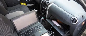
The most complete diagnosis is possible with a computer or laptop. In order to use this method, you must purchase an adapter. This adapter performs two functions at once. It is an adapter from a K-line port to a USB port or to a COM port. It also acts as a decoder, which allows you to transmit signals from the ECU to the PC. You will also need to install the appropriate software on your laptop. There are a lot of free versions on the Internet. There are universal programs, as well as programs written for a specific car. After connecting to the computer, you will need to turn on the ignition and launch the program. The connection will happen automatically.
The interface of the computer program is very convenient and allows even an inexperienced user to navigate intuitively. All functionality can be divided into several sections. These are parameters, errors and settings. If the first two sections are informational, then using the third section you can control the vehicle systems.
Diagnostics using third-party equipment
More precisely, errors on Chevy Niva can be identified by connecting additional equipment. The technique is more technically complex, but allows us to determine the cause of a breakdown or failure with minimal error. In this case, the sequence of actions is as follows:
If all actions are performed correctly, all available information and any errors in the form of encrypted codes will be displayed in the desktop window.
There are also specialized scanners designed specifically for Chevrolet NIVA. Dealer devices are connected to the place of the standard signaling unit through an output cable.
Separately, we should highlight modern devices designed to connect a smartphone to a car, while reading encodings and controlling operating modes occurs directly from the gadget’s display.
At the same time, you should know what the encodings displayed during diagnostics mean. The code consists of several elements.
The next element is a single digit:
The following digit determines the exact serial number of the line in which the defect was detected:
