Cars admin26.02.2020
Help with advice. The tachometer and power steering don't work, the speedometer jumps, the generator gives 14.5. It all started about two weeks ago. I tried almost everything, but still nothing. After replacing the phase sensor, everything worked for a couple of days and again everything remained the same. Or rather, the speedometer has also been added while driving like a dragonfly under 200 km. Moreover, the speed was city, although after 40 minutes it was restored to normal mode. And everything else is the same. Where else to go. I'm thinking.
Hurray, it worked! The problem is resolved, it’s just that antifreeze flooded the brain. I didn’t visually notice small drops between the microcircuit legs, I thought that was it. As a result, alcohol-based cologne) and a day of drying the board on the radiator. We turned on the ignition and EVERYTHING WORKED. My wife sat up to the ceiling with joy that the EUR worked))
Today, all Lada Kalina owners are interested in the question: why does the electric power steering on the Kalina not work? After all, this car began to be produced back in November 2004, with electric power steering as standard. The ten-year anniversary has passed, but according to reviews from car enthusiasts, this problem still exists.
The electric amplifier consists of an electric motor, a force transmission mechanism and an electronic control system. The operation of the electric booster is controlled by an electronic unit with three special sensors, which must quickly determine the speed of the car, engine speed and the required force to turn the front wheels.
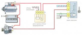
When starting the engine with the starter, the electric power steering (EPS) does not work. It turns on only when reaching 400 rpm
crankshaft and stops working when the car accelerates over 60 km. at one o'clock.
Classification by operating principle
- Mechanical or electromechanical tachometers with direct drive. The revolutions are transmitted to the dial indicator through a flexible shaft, which, through a worm gear, receives rotation directly from the crankshaft or one of the transmission shafts. The operating principle of the indicator is based on the phenomenon of eddy current induction. The operation and design of a magnetic tachometer are extremely similar to the operating principle of a car speedometer. In modern cars, a similar tachometer design is not used.
- Electric machine. A distinctive feature is the connection to a generator. It is used primarily on diesel engines, but for the purpose of unification, a device of this type can also be used on gasoline engines.
- Electronic. The signal can be taken either from the ignition system or directly from the computer. Installed on gasoline and diesel internal combustion engines.
Design and principle of operation
Main components of electric machine and electronic tachometers:
- measuring unit, or signal converter. It can be based on elements of analog circuitry or built using special microcircuits;
- display unit with analogue or digital display of the number of revolutions;
- auxiliary elements.
The operation of electronic tachometers is based on the conversion of individual signals or pulses captured from the computer, ignition system or generator into a signal “understandable” for the display unit.
Connection diagram
When looking for the reason why the tachometer does not work, it is first of all important to understand the connection diagram and the type of signal. There are 3 typical connection schemes:
- to a contactless ignition system (the tachometer wire is connected to the primary circuit of the ignition coil). The operating principle is based on measuring the frequency of voltage surges in the primary circuit of the ignition system. Calculating the ignition angle is impossible without focusing on the number of crankshaft revolutions, therefore the sparking frequency directly depends on the crankshaft rotation speed. On 4-cylinder internal combustion engines, a full revolution of the crankshaft corresponds to 2 voltage pulses in the primary circuit. Accordingly, the higher the crankshaft rotation speed, the greater the frequency of voltage surges;
- connection to the contact ignition system. The operating principle and connection diagram are similar to the BSZ, but the design of the measuring unit will differ depending on the voltage of the input circuit;
- connection to the engine ECU. The principle of operation is still based on recording voltage pulses in the primary circuit of the ignition system, but the signal to the tachometer comes from the engine control unit;
- connection to the generator (the tachometer signal contact is connected to terminal W of the generator). The rotation of the generator pulley is carried out by a belt drive from the crankshaft, so the rotation speed of the generator rotor will always be proportional to the crankshaft speed. The change in the number of revolutions of the crankshaft can be calculated by constantly measuring the amount of EMF generated on the winding. According to its principle of operation, an electric machine tachometer resembles a regular one class=”aligncenter” width=”448″ height=”412″[/img]
EUR and tachometer do not work - automaster.net
Description of contacts ECU M7.9.7 / January 7.2 Blue indicates contacts used in systems with 2 DCs (Euro III) Red indicates contacts used in 16 DC systems 21124
| № | Compound |
| 1 | 21114 - Not used / 21124 - Ignition coil 2 cylinders. |
| 2 | 21114 - Ignition 2-3. Control of the primary winding of the ignition coil, act. level is low. / 21124 — Ignition coil 3 cylinders. |
| 3 | Ignition circuit weight |
| 4 | 21114 - Not used / 21124 - Ignition coil 4 cylinders. |
| 5 | 21114 - Ignition 1-4. Control of the primary winding of the ignition coil, act. level is low. / 21124 - Ignition coil of cylinder 1. |
| 6 | Injector 2. Active level low |
| 7 | Injector 3. Active level low |
| 8 | Output to tachometer. |
| 9 | Not used |
| 10 | Fuel consumption signal |
| 11 | Not used |
| 12 | Battery, terminal 30 of the ignition switch. |
| 13 | Nutrition. Ignition switch terminal 15 |
| 14 | Main relay |
| 15 | Contact "A" DPKV |
| 16 | TPDZ |
| 17 | TPS mass / TPS mass, DND |
| 18 | Input - oxygen sensor |
| 19 | Input - knock sensor |
| 20 | Knock sensor weight |
| 21 | Not used |
| 22 | Not used |
| 23 | Not used |
| 24 | Not used |
| 25 | Bosch Only - High Current Output, Reserved |
| 26 | Bosch Only - High Current Output, Reserved |
| 27 | Injector 1. Active level low |
| 28 | Not used / DK2 heater control output |
| 29 | Not used / Engine cooling fan control output 2 |
| 30 | Not used |
| 31 | CE lamp, act. level low |
| 32 | Power supply TPDZ / Power supply TPDZ, DND |
| 33 | Power supply for mass air flow sensor |
| 34 | DPKV input, contact “B” |
| 35 | Weight of DTOZH / Weight of DTOZH, mass air flow sensor, 1 DC (UDK), 2 DC (DDK) |
| 36 | Mass of the mass air flow sensor |
| 37 | Signal input from mass air flow sensor |
| 38 | Not used |
| 39 | Signal input from DTOZH |
| 40 | Signal input from intake air temperature sensor |
| 41 | Not used |
| 42 | Not used / DND signal input |
| 43 | Not used |
| 44 | On-board voltage input at the main relay output |
| 45 | Phase sensor power output |
| 46 | Canister purge valve control output |
| 47 | Injector 4. Active level low |
| 48 | Oxygen sensor heater control output |
| 49 | Not used |
| 50 | Additional starter relay control output |
| 51 | Controller weight |
| 52 | Not used |
| 53 | Controller weight |
| 54 | Not used |
| 55 | Not used / Signal input DK2 (DDK) |
| 56 | Not used |
| 57 | Input for encoding calibration data options. The controller memory can contain 2 sets of calibration data; switching is performed by shorting to ground. |
| 58 | Not used |
| 59 | Speed sensor |
| 60 | Not used |
| 61 | Weight of output stages |
| 62 | Not used |
| 63 | On-board voltage input at the main relay output |
| 64 | Output “D” IAC |
| 65 | Output “C” IAC |
| 66 | Output “B” IAC |
| 67 | Output “A” IAC |
| 68 | Engine cooling fan relay control output, act. level - low |
| 69 | Air conditioner relay control output, act. level - low |
| 70 | Fuel pump relay control output, act. level - low |
| 71 | K-Line |
| 72 | Not used |
| 73 | Not used |
| 74 | Not used |
| 75 | Input request to turn on the air conditioner, act. level - high |
| 76 | Power steering request input, act. level - high |
| 77 | Not used |
| 78 | Not used |
| 79 | Phase sensor signal input |
| 80 | Weight of output stages |
| 81 | Not used |
Tips for motorists
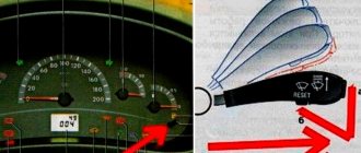
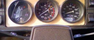
On the left side of the instrument cluster of the Lada Kalina passenger car, there is a tachometer, from which the driver can determine the engine speed. Malfunctions in the electrical circuit of this device can lead either to a complete cessation of its readings (the tachometer needle is at zero when the engine is running), or to jumps in the needle on the scale, which does not allow determining the exact number of crankshaft revolutions.
The first thing drivers do in this case is open the hood and remove the negative terminal of the battery for a couple of minutes, thus trying to clear errors from the controller’s memory. If this does not help restore the tachometer to working order, then it is necessary to conduct a diagnostic test to identify error numbers. To do this, use your finger to press the button, which resets the daily mileage in the instrument cluster odometer. And without releasing it, turn the key in the ignition switch to the “ignition on” position.
All instrument needles must begin to move from the zero position to the final position and back. If the tachometer needle does not start moving or starts moving but does not return to its original position, this will indicate that the malfunction is located inside the instrument cluster. Considering that the stepper motors, with the help of which the tachometer needle moves, and circuit boards are not available for retail sale, the entire instrument cluster assembly will have to be changed.
If the tachometer passes the test, then the fault will have to be looked for outside the instrument cluster. On their own, most drivers can only check the condition of the terminals in the tachometer electrical circuit blocks, since this can be done visually. First of all, you need to check terminal No. 30 of the low-voltage tachometer input, which should be connected to the brown-red wire coming from the electronic control unit (ECU). To do this, you will need to remove the instrument cluster by disconnecting the wiring harness block from it. Terminal No. 30 should not be bent or show signs of corrosion.
Debriefing
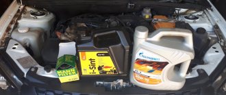
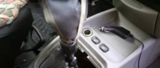
The electronic control unit (ECU) for the electric power steering is mounted in the wrong place, under the heater radiator. Any leakage of this part causes the ECU to get wet, after which you will feel that the power steering is not working and the steering wheel has become heavy.
If while driving you notice that the tachometer or speedometer needle is at zero and does not move, rest assured that the ESD of your car is not working. This happens because these devices and (EUR) are activated from the same sensors.
Most often on Kalina, the speed sensor fails. Buying a new sensor and replacing it solves this problem. There are very often cases when replacing sensors does not help, (the electric power steering) still does not work. Begin to methodically probe the entire chain of wires related to the system (EUR).
Due to the constant vibration of the car and poor quality of production, connecting plugs and blocks independently break electrical circuits at the most inopportune moment.
Kalina's power steering behaves poorly when the on-board voltage drops. If an old generator produces less than 30 volts instead of 15 volts, then the electronic control unit of the power steering may also refuse to work.
Causes of malfunction
So, basically the malfunction appears due to disassembling the instrument cluster. On many forums, car owners complain that after disassembling the panel, this defect appeared.
But this may not be the only reason . Let's consider the main ones:
- The tachometer control motor burned out.
- The tachometer controller has failed.
- Error in the electronic control unit.
- Part of the instrument cluster board was burnt.
Thus, the main problems have been found.
Disassembling the dashboard
Treatment methods
In order for the tachometer needle to return to its place, it is necessary to eliminate the causes of this effect. So, let's look at how to treat various malfunctions with your own hands:
- The motor burned out. It is necessary to unscrew the panel and unsolder the element contacts. Check the resistance, which should be 300 ohms. If necessary, clean the contacts and solder the motor back. If this does not work and there is no resistance, then you need to install a new motor.
- Tachometer controller . If the motor is sealed and the tachometer does not return, then you need to find the control controller and check it. Replace if necessary.
Now we know how to eliminate the causes of the malfunction.
Diagnostics
To check the amplifier in a car, you need to remove the plastic trim on the steering column; to do this, unscrew the bolts securing it from the bottom.
Then you will need to get to the 8-pin plug, its pinout is as follows:
- The blue contact is connected to the ignition switch, this is 12 volt power;
- the red-brown contact is the connection cable to the tachometer;
- the gray contact goes to the car speed controller;
- white and pink wire - amplifier control indicator;
- black-yellow contact is a diagnostic line;
- the next contact is empty, the wire is not connected to it;
- brown contact is ground;
- empty.
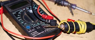
More accurate results will be obtained by checking the amplifier using a scanner. But since such equipment can usually only be found at service stations, you can try to check the operation of the system with a paper clip.
To check you need to do the following:
- First the ignition is turned off.
- Then, using a paper clip, you need to close contacts numbered 6 and 7 of this plug, while the plug itself does not need to be removed.
- Next, the ignition must be turned on.
- After completing these steps, the EUR failure indicator located in the dashboard will begin to blink; by the number of blinks, you can determine whether the system is broken (the author of the video is Gosha Vakhromeev).
How to understand where to look for the cause by the blinking indicator icons:
- one long signal and one short signal - the electric amplifier is working;
- one long and two short - no engine speed signal;
- one long and three short - the torque controller is out of order or there is no power supply;
- one long and four short blinks—problems in the operation of the electric power steering motor;
- one long and five short - the steering shaft position controller has failed;
- one long and six short - the motor rotor position controller has failed;
- one long and seven short - problems with the electrical network - the voltage is either too high or very low;
- one long and eight short - the control module of the electric amplifier has failed;
- one long and nine short - the speed controller is broken.
Error codes
c1044 - incorrect sequence of the rotor position sensor (RPS)
c1621 - incorrect voltage 5V
c1622 - speed signal circuit failure
c1011 - car engine speed signal circuit, no signal - the signal from the idle sensor (or the standard tachometer through a voltage limiter) is divided by 4 and applied to the tachometer input,
c1022 - error, voltage of the main output of the torque sensor - it is possible that the shaft cover has rubbed the insulation and the middle, green wire shorts to ground
What does the tachometer jump at high speeds indicate?
If the tachometer needle jumps during a trip or at high speeds, then the problem is also associated, as a rule, with the car’s engine. But before contacting a car mechanic, you can independently check the presence of fuel in the tank, inspect the camshaft drive chain, the timing belt that connects the crankshaft and the camshaft; perhaps it is loose and needs to be tightened. These are the main and frivolous reasons that can cause interruptions in engines and jumps in its speed.
If no visible problems are found with these elements, then you should go to an auto mechanic. Delay and failure to respond to a signal such as unstable tachograph operation can lead to serious damage to the vehicle’s cylinder-piston system and costly repairs.
It is better not to engage in diagnostics and independent repairs if the tachometer needle is floating. You should trust specialists who, using special equipment, will identify and eliminate the causes of the failure.
Test 8
Establish a correspondence between the sentences and the grammatical errors made in them: for each position in the first column, select the corresponding position from the second column.
| GRAMMATICAL ERRORS A) incorrect use of the case form of a noun with a preposition B) violation in the construction of a sentence with an inconsistent application C) violation in the construction of sentences with participial phrases D) error in constructing a sentence with homogeneous members D) incorrect construction of a sentence with an adverbial phrase | OFFERS 1) In the western part of the estate there is the building of the famous Yusupov Theater, designed by the famous Moscow architect O. I. Bove. 2) At the end of the exams you will receive certificates. 3) Being one of the main drivers of the plot, it is impossible not to appreciate the role of magic in fantasy. 4) The Nepalese government announced that it is reducing the fee for climbing Everest from 18 to 8 thousand euros, provided that each climber not only brings down all his waste, but also takes 8 kilograms of garbage left by his predecessors. 5) Not numbers, not reports, but only a person from another time, with his fate, testifies to an era - to a life that has sunk irrevocably. 6) The first stories of the modern Russian writer Viktor Remizov were published in the magazine “New World”. 7) After removing the snow on the path near the gate, lean a piece of old slate against it so that the slate covers at least 40-50 cm of the path, and then after the next snowfall, to open the gate, it will be enough to simply lift the slate. Sonechka knows how to love, sacrifice, care and keep faith. 9) Of those who are able to wake up at the appointed time, only a fifth confidently said that they kept the scheduled time with an accuracy of plus or minus 10 minutes. |