Let's be honest - the VAZ 2110 does not have the most beautiful “native” instrument panel, either on the first cars or on the “improved” ones. Therefore, many owners of this model are trying to make it more modern and somehow decorate it (with LEDs, beautiful lights, etc.).
But, before you decide on some kind of upgrade, it is necessary that you have before your eyes the pinout of the instrument panel for the VAZ 2110, otherwise you can simply get lost in a heap of wires, sensors and buttons. Moreover, it will be useful regardless of whether you completely change the panel, or simply make some additions to the dashboard of your VAZ 2110.
Instrument panel VAZ 2110
Connection knowledge
Before starting dismantling work, you need at least a conventional pinout on paper, otherwise it will be very difficult: you will need to “trace” every wire and every connection that is on the “path” from the devices to the power button.
In fact, the pinout of the VAZ 2110 dashboard is not so difficult to understand, but there are differences between cars produced in different years and at different factories. There is an old model, there is one with a mechanical odometer, and a new (Euro) model, so there are differences in the pinout of the instrument panel, depending on the type to which it belongs.
Instructions for installing the Europanel on a VAZ 2110 can be found here:
Why you should know the pinout
But before you start this kind of upgrade, you need to understand which wire leads where. The pinout of the instrument panel of a VAZ-2110 car is a very important point when “tuning”. Without this, you risk simply getting confused in a fairly large number of wires, buttons and various sensors. The pinout will be useful in any case - both when making minor improvements and when completely replacing the instrument panel.
The process of installation and dismantling itself is quite labor-intensive, but if you know the correct sequence of actions, then there is nothing particularly difficult about it.
For these works you will need a minimum set of tools - a screwdriver and pliers.
For those who are doing this for the first time, it is best to stock up on self-adhesive pieces of paper, like those on which prices are written in stores, and a pen. With their help, at the time of disassembly, you will indicate, firstly, the sequence of dismantling the parts, and secondly, which wire is connected where. At first glance, this may seem time-consuming, but in fact, for beginners, such markings will help them put the panel back together faster.
At the same time, before starting work, it is best to stock up on a pinout diagram - at least conditional. After all, during the work process you need not to confuse anything and correctly understand each wire and connection during the reassembly process. It is worth noting one very important point. By and large, understanding the pinout of the panel of the “tenth” family will not be difficult even for a beginner.
But you need to remember that there are certain differences here, depending on the plant where the car was manufactured and the year of its manufacture. For example, the instrument panel may be an old model, with a mechanical odometer. If the odometer is electronic, then this is a newer version. Accordingly, there are certain differences in pinout between these panels.
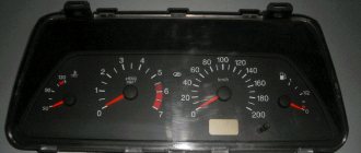
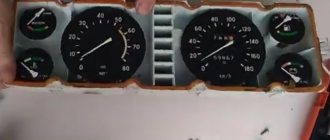
General diagram of devices
If you look from the back of the instrument panel, here it is in sequence - from top to left to right:
- Fuel level indicator;
- Combination of instrument lighting lamps;
- Right turn control;
- Left turn control;
- Tachometer;
- Next is the block, there are a lot of plugs in it;
- And the top part of the dashboard is completed by an antifreeze temperature indicator.
VAZ 2110 dashboard connection diagram
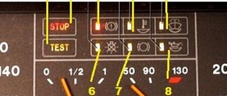
The lower part of the dashboard (also from left to right and from the back of the dashboard). The following part of the instruments is located here:
- high beam controller (bulb);
- alarm controller;
- brake fluid level control lamp;
- speedometer;
- CHECK ENGINE controller;
- battery charge control;
- parking brake controller;
- oil pressure controller;
- air damper controller in the carburetor;
- outdoor lighting controller.
You can familiarize yourself with speedometer malfunctions in this material:
White block
The connector number, wire color and the unit (assembly) to which it goes are located in the white block as follows:
- The first connector has a black wire. Its purpose is the body (mass);
- In the second - red-brown - this is a low-voltage supply from the electronic control unit - tachometer;
- The third, yellow one is also a tachometer, but this is a high-voltage supply from a coil;
- The fourth, red-blue is Const from the battery + 12V, going through the sixth fuse;
- The fifth, green-white - it is intended to indicate the coolant temperature;
- Sixth, green-yellow – for size fuse F1;
- The seventh connector does not have its own color and goes to the “choke”, the throttle valve;
- Eighth, red and white - CHECK ENGINE light;
- In the ninth and tenth there are 2 orange wires each, leading to 2 power fuses F19+12V;
- In the eleventh there are 2 blue-brown wires leading to the “BK” terminal of the parking brake;
- The twelfth, brown-white is the output “D” of the generator;
- Thirteenth, gray and blue – for the oil pressure sensor.
White block (X1) and Red block (X2) of the VAZ 2110 instrument panel
Red block
The number is the connector according to the account, followed by the color of the wire and an indication of the device to which it goes in the red block of the VAZ 2110:
- Blue and red go to the sensor showing the external temperature;
- Orange - power fuse F19+12V;
- Black, 2 wires – ground, body;
- White - light switch for all devices;
- Blue - right direction indicator;
- Blue and black - left turn signal;
- Blue with pink - TJ level;
- Brown – leading to the trip computer;
- Gray - speed indicator;
- Pink - Fuel gauge (terminal “T”);
- 2 black-green wires - high beam fuse (F3);
- Blue and white - emergency light switch;
- White - leading to the ignition switch (terminal 50).
An article dedicated to tuning the dashboard backlight can be found here:
Repair or replacement of the VAZ dashboard
If on a car on the instrument panel none of the indicators installed on it work (speedometer, odometer, tachometer, fuel level and coolant temperature indicators), then the first thing the driver will have to do is check the integrity of fuse F3, which is located in the mounting block . If it has burned out, then before replacing it, you need to find the reason why it burned out, otherwise the newly installed new fuse will have the same fate as the previous one. Most often, fuses burn as a result of a short circuit.
Even if the fuse is intact, then do not be lazy to take it out and check the condition of the contacts. There are cases when the contacts oxidize, and the electrical circuit in this place is interrupted. After making sure that the fuse is intact, the next step is to check the ignition relay, which is located inside the car to the left of the steering column. It is attached to a pin upside down. In the block where this relay is inserted, you can try to short-circuit the power wires using a jumper. If the instrument panel comes to life, the ignition relay will have to be replaced.
If the ignition relay is working properly, there are only two possible reasons for the instrument panel not working: the ignition switch and the mounting block. Before installation on the VAZ-2109 car, the ignition relay and lock contacts often burned out and had to be cleaned by disconnecting the contact group from the lock itself. After changes were made to the principle of supplying voltage to the ignition switch, its contacts began to burn very rarely, but the likelihood of this phenomenon still remained. On the mounting block, in its board, tracks may burn out; in order to see this, the mounting block will have to be removed from the car.
In addition to the reasons listed above, which can lead to failure of the instrument panel, it is also necessary to check the reliability of the fastening of the ground wire. Most common problems:
- burnout of incandescent lamps or failure of the LED group;
- oxidation of connectors;
- electrical wiring fault;
- failure of the fuse box;
- damage to the common contact board;
- no weight on the body (minus) or damage to the dimensions system.
To find a fault, you must use diagnostic equipment, a tester or a voltmeter. If a breakdown is found, you can begin repairs.
Nuances of work
However, these pinout diagrams for the VAZ 2110 are, so to speak, basic, mostly the same, but there are also differences in color markings (especially by manufacturer). Therefore, you need to either use the instruction manual that came specifically with your car, or, armed with a marker and self-adhesive labels, “write everything out” in detail and not get confused when installing a new instrument panel.
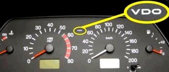
Connecting wires to the VDO panel on a VAZ 2110
Connecting wires to the “Schetmash” panel in Kursk on a VAZ 2110
Connecting wires to the “AP” panel in Vladimir on a VAZ 2110
Connecting wires to the panel from the Kalina car to the VAZ 2110
During subsequent assembly, there will probably be a lot of devices that are not taken into account here, and, taking into account modern realities, many car owners plan to install them on the updated dashboard.
Features of connecting BC
In conclusion, I would like to dwell in more detail on such a point as installing an on-board computer. In the typical pinout diagram shown just above, there is only one wire leading to it - brown. But for the correct operation of this device, this alone will not be enough. Therefore, here is a complete pinout diagram for connecting the on-board computer:
- Green wire – comes from the electronic control unit, needed to obtain information about fuel consumption.
- Orange – goes to the ignition switch, to terminal 15.
- White-red - in the same place, only to terminal 30.
- The common ground wire is black.
- Brown – needed to take speed data.
- Red-green - to the positive circuit of the fuel level sensor.
- White - leads to the light control, which is responsible for the lamps that illuminate the instrument panel.
Connecting the trip computer
The mentioned diagram took into account only one, brown wire leading from the red block to the trip computer, but this is clearly not enough. Therefore, let's see how the pinout occurs here.
- The fuel consumption signal from the electronic control unit is indicated by a green wire;
- Orange leads to terminal “15” in the ignition switch;
- Red and white - to terminal “30” in the ignition switch;
- Black, which is common, goes to ground;
- The speed indicator corresponds to brown;
- The positive terminal of the fuel sensor is green and red;
- Responsible for lighting the dashboard white, it leads to the light control.
Make sure that the board is not damaged, on which, in fact, uninterrupted reading of information from your VAZ 2110 depends, and providing it to you through all those sensors and devices that you always see in front of you.
- Author: ratico19
Rate this article:
- 5
- 4
- 3
- 2
- 1
(14 votes, average: 3.4 out of 5)
Share with your friends!
Electrical diagram of VAZ-2112
Designations: 1 – Headlight, 2 – Klaxon, 3 – Main radiator fan, 4 – Starter, 5 – Battery, 6 – Generator 2112, 7 – Gearbox limit switch (reverse), 8 – Actuator in the front passenger door, 9 – Power window enable relay, 10 – Starter relay, 11 – Heater fan, 12 – Electric heater partition drive, 13 – Main pump, 14 – Washer reservoir sensor, 15 – Driver’s door actuator, 16 – Front passenger window selector, 17 – Unlock button fifth door, 18 – Heater fan resistance unit, 19 – Main wiper motor, 20 – Driver’s window lift selector, 21 – Front passenger’s window lift motor, 22 – Central locking, 23 – Exterior light switch, 24 – Brake fluid leakage sensor, 25 – Pump additional, 26 – Driver's window lift motor, 27 – PTF on indicator, 28 – PTF switch, 29 – Dashboard, 30 – Heated glass on indicator, 31 – Heated glass switch, 32 – Steering column selector switch, 33 – PTF relay, 34 – Ignition switch, 35 – Main fuse block, 36 – Illumination of heater controls, 37 – Hazard warning button, 38 – Heater control controller, 39 – Glove compartment lighting, 40 – Glove compartment lid end cap, 41 – Cigarette lighter, 42 – BSK – display unit, 43 – Ashtray illumination, 44 – 12V socket, 45 – Instrument lighting switch, 46 – Actuator in the right rear door, 47 – Right rear passenger window selector, 48 – Clock, 49 – Right rear passenger window motor, 50 – Brake limit switch (closed – pedal is pressed), 51 – Left rear passenger window motor, 52 – Left rear passenger window selector, 53 – Actuator in the left rear door, 54 – Turn signal, 55 – Handbrake limit switch (closed – handbrake on), 56 – Rear wiper motor , 57 – Navigator's lamp, 58 – Interior lamp, 59 – Temperature sensor in the heater, 60 – Limit switch for the open front door, 61 – Limit switch for the open rear door, 62 – Trunk light, 63 – Rear optics (on the body), 64 – Rear optics (on the fifth door), 65 – License plate illumination.
The letters indicate the terminals to which it is connected: A – Front speaker on the right, B – Radio, C – Injector harness, D – ESD diagnostic connector, D – Front left speaker, E – Diagnostic connector for the heater controller, G – Rear right speaker, W – Rear left speaker, I – BC connector, K – glass heater thread, L – fifth door actuator, M – Additional brake light.
Wiring diagram VAZ-2112 injector 16 valves - full view