ISO pinout or pinout is the identification of each electrical connection pin in a connector or diagram according to its corresponding numbering and functionality. The speaker system of any manufacturer is connected to the standard ISO connectors of the car. Proper pinout will help you get a good sound at the output and not burn out the connectors with voltage. You can understand the wires using standard diagrams. You can install any brand of car radio without having specialized knowledge in electrical engineering. When working with non-standard connectors, do not forget about safety. “Ring” the wires using a multimeter.
What is iso
ISO is an international organization that develops standards and regulations for various industries. The abbreviation sounds the same in all languages. A Russian manufacturer working in accordance with standards labels its products with the abbreviation “ISO” or “ISO”. All well-known developers of car radios equip their products with two types of standard plugs. Each looks like an eight-pin rectangular connector.
What can you encounter if your car radio is not connected correctly?
This is not to say that to properly install a radio, you don’t need to have any skills at all. It is advisable to have at least initial experience in connecting electrical devices, but this is not a prerequisite; following the instructions, a person can complete the installation without any experience. To understand whether everything was done correctly, it is worth monitoring the operation of the radio. A sign of an error will be the presence of the following factors:
- The radio turns off when the volume is increased.
- When you turn off the ignition, the radio settings are lost.
- The radio drains the battery when turned off.
- The audio signal is noticeably distorted, especially when listening at high volumes.
In very rare situations, it is not the person who connected it who is to blame, but the seller who sold the low-quality product. Of course, this option cannot be ruled out, but you will still need to double-check the connection diagram.
Pinout of a standard Euro connector
A Euro connector is a standard plug used in most countries around the world. When connecting equipment, you may encounter non-standard wires tangled in a bundle. This problem is solved by purchasing adapters and pinouting the radio chips.
Standards 1din and 2din
Speaker system connectors come in two types: non-standard ones from the manufacturer, mostly pin-type, and standardized European ones, which are located at the back. Installation of equipment with a special audio connector from the manufacturer will require the use of a special proprietary connector. If the plug is ISO, then you can connect to it directly. There are two types of Euro connectors: 1din and 2din, the difference is in the height of the car radios. The two-block one is twice as tall; it is not connected to all cars, because there is no space on the panel for the required dimensions.
Radios with European 1din are the most common.
When installing car radios, wires with a small diameter of 1.5-2 mm are used, for power lines - with a large cross-section. Failure to follow these simple rules will distort the sound and damage the equipment.
| № 1 | — |
| № 2 | — |
| № 3 | — |
| № 4 | Constant power |
| № 5 | Antenna power |
| № 6 | Backlight |
| № 7 | Ignition |
| № 8 | Weight |
Manufacturers in Japan, the USA and some Chinese use the 2din standard.
Upper power connector A
The plug is used to supply electricity to the receiver, antenna and amplifier, as well as when it is necessary to control the backlight or turn off the sound signal. Standard color markings are used. Outputs 1-3 and 6 are not used in low- and mid-price segment speakers; they are intended for additional options for high-end products.
Connection types
- The first is the connection in the socket of wires of two colors, yellow and red, turning the receiver on/off does not depend on the ignition. The method is inconvenient because it predisposes the battery to discharge if the acoustics are not turned off;
- The second wire is connected through the ignition switch, the yellow wire is connected to the on-board computer.
Functional purpose of the receiver outputs
| ANT | The connector is used if the car has a retractable antenna |
| Remote | Multiple speakers can be connected |
| Illumination | Allows you to change the intensity of the device's glow |
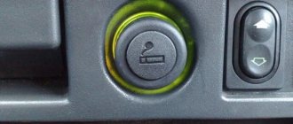
| Mute | Adjusting the sound |
| A4 | Turn on/off |
Pinout of radio ISO connector
| A 4 | Color yellow | Battery + Power |
| A 5 | Color blue | Antenna. |
| A 6 | Color orange | Backlight |
| A 7 | Color red | Ignition, 12V. When disconnected, reset settings to factory settings. |
| A 8 | Color black | Acoustics |
Bottom speaker connector B
Used to connect amplifiers (2 cables each). The sound of the equipment depends on whether all connectors are connected correctly. The main thing is not to confuse them, otherwise the acoustics will be of poor quality.
Rules for connecting speakers by color marking of wires
| Color white | Left front |
| Color grey | Right front |
| Color green | Left rear |
| Color violet | Right rear |
Dimensions
There are two main form factors for radios, these are 1-DIN and 2-DIN (DIN (abbr.) - German Deutsches Institut für Normung eV . - German Institute for Standardization).
The depth is not standardized, but is usually 160 mm. for both options.
Today, replacing a 1-DIN radio with a 2-DIN and vice versa is not difficult, the presence of a huge number of adapter frames contributes to this, thanks to our Chinese brothers!
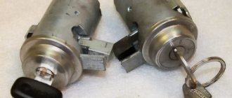
Dual ISO connector
The standard audio systems of some cars are connected with a double plug. The pinout of connectors for them is standard. The contact halves are connected to each other by a durable plastic jumper and secured with a special clamp. For correct installation, a guide groove is used, which prevents the plug from being installed in the wrong position.
The black one connects a current source to the radio, the brown one for acoustics.
Through the ignition switch
This method is considered the safest and optimal. Each radio comes with instructions that describe this type of connection. But, despite the positive aspects that most car enthusiasts agree on, there is also a minus, namely the inability to listen to music without the ignition or engine on. Connecting according to this scheme is the simplest; you need to connect the yellow wire (plus) to the positive terminal of the battery. The black wire is to the ignition switch, it is responsible for turning it on. And minus to the weight of the car. With this type of connection, you don’t have to worry about the battery running out.
Adapters for ISO connectors
Cutting off a non-standard standard plug and connecting the wires directly is not recommended, because over time the connection will become loose, may oxidize, you will have to solder not only the wiring, additional repairs will be required, replacing blown fuses. Sometimes there are acoustics with three outputs, but they have standardized markings and electrical circuits that allow you to connect standard cables to the device using pinouts. You can buy any type of adapter for ISO connectors from one model to another.
The car may not be equipped with connectors, then you need to connect the radio connector to the cable directly. This is done by twisting, soldering, or using a terminal block that does not require subsequent insulation. When twisting and soldering, heat shrink tubing is used for safe use of the equipment.
Page 41
Purple/White (REVERSE GEAR SIGNAL INPUT)
It is connected so that the navigation system can detect whether the car is moving forward or backward. Connect the purple/white wire to the wire that changes voltage when reverse is engaged. If not connected, the sensor may not detect the correct forward/reverse movement of your vehicle and thus the position of your vehicle detected by the sensor may not match the actual position.
When you use the rear view camera, please make sure to connect this wire. Otherwise, you will not be able to turn on the image from the rear view camera.
Be sure to use the extension cord supplied. Use of other cords may cause fire, smoke, and/or damage to this navigation system.
Clamp the reverse lamp wire.
Grip firmly with needle nose pliers.
Extension cable (for speed signal)
Extension cable (for return signal)
Reversing lamp wire
Check the position of your vehicle's reverse light (the one that lights up when the shift lever is in reverse [R]) and locate the reverse light wire in the trunk.
Generally accepted standards establish the designation of radio wires by color. This allows you to accurately determine the purpose of each of them in order to connect correctly and safely.
Pinouts for various brands of cars and radios
Before getting started, read the instructions for the receiver, and also pay attention to the markings and features of the product itself. The pinout of radios is influenced by standard connectors in different cars.
Pinout diagram for ISO connectors for pioneer radios
Connecting the acoustics of this well-known brand, which is popular among motorists, has some features. Be sure to read the installation manual before starting work. Installation is simple, the main thing is to understand the purpose of each color. In addition to the instructions, the kit includes two “chips” with 4 pairs of contacts: for power and acoustics.
The pinout of the plug has 10-20 outputs, the functionality of each connector varies depending on the model. The KEH series is characterized by the following circuit: No. 1 - antenna, No. 2 - ignition, No. 3-6 and 8-11 - amplifiers. To avoid confusion, please read the instructions carefully.
In order not to burn out the acoustics, before connecting the speakers you need to connect the radio, check that it lights up and switches.
toyota
The pinout of acoustics of this brand is carried out according to standard diagrams. It is optimal to choose a power supply system from a battery, in this case there is no risk of its discharge.
ISO connector:
| № 1 | A+ |
| № 2 | GND |
| № 3 | BAT+ |
| № 4 | Backlight |
| № 5 | Antenna |
| № 6 | Speakers (RR+, RR-, RF+, RF-, LF+, LF-, LR+, LR-) |
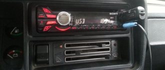
sony
When connecting the radio, standard circuits are used.
| № 1 | ANT |
| № 3 | L.R. Line output |
| № 4 | GND. Line output |
| № 5 | R.R. Line output |
| № 6 | CD–LCH |
| № 7 | CD - GND |
| № 8 | CD–RCH |
| № 9 | CD - Reset |
| № 10 | CD – CD clock out |
| № 11 | CD – DSPL select |
| № 12 | CD – data out |
| № 13 | CD – clock in |
| № 14 | CD – data in |
| № 16 | A+ |
| № 17 | GND |
| № 18 | ANT GND |
| № 22-27 | Speakers (LF-, LR+, RF-, RR+, LF+, LR-, RF+, RR-) |
| № 28 | Mute |
| № 29-30 | Speakers (LF-, LR+, RF-, RR+, LF+, LR-, RF+, RR-) |
| № 31 | ANT CONT |
| № 32 | CD ACC Constant |
| № 33 | AMP Constant |
| № 34 | BUP |
nissan
Universal connector:
| № 1-6 | Speakers (LR+, RR+, LR-, RR-, LF+, RF+) |
| № 7 | A+ |
| № 8 | Backlight |
| № 9 | BAT+ |
| № 10 | Speakers LF- |
| № 11 | RF speaker |
| № 12 | Antenna |
| № 13 | GND |
honda
All models of car radios are equipped with a universal European plug for connection to the socket.
| № 1 | Speaker RR+ |
| № 2 | Speaker LR+ |
| № 3 | Backlight |
| № 4 | BAT+ |
| № 5 | A+ |
| № 6 | Antenna |
| № 7-10 | Speakers LF+, RF+, RR-, LR- |
| № 13 | GND |
| № 14-15 | Speakers LF-, RF- |
bmw
Standard European pinout.
| № 1 | A+ |
| № 2 | BAT+ |
| № 3 | GND |
| № 4 | — |
| № 5-12 | Speakers RR+, RR-, LF+, LF-, RF+, RF-, LR+, LR- |
alpine
Alpine TDE-7823W: 1 – BAT+,
| № 2-5 | Speakers LR-, LR+, RR-, RR+ |
| № 7 | Amplifier |
| № 8 | Antenna |
| № 9 | GND |
| № 10-13 | Speakers LF-, LF+, RF-, RF+ |
| № 5-12 | A+ |
mitsubishi
All models use standard European speaker pinout.
| № 1-2 | Speakers RR+, LR+ |
| № 3 | Antenna control |
| № 4 | Backlight control |
| № 5-8 | Speakers LF+, RF+, RR-, LR- |
| № 10 | A+ |
| № 11 | BAT+ |
| № 12 | Backlight control |
| № 13-14 | Speakers LF-, RF- |
| GND |
Instructions for adjusting the backlight with a rotary encoder
Do the following:
- Click on the rotator (valcoder) and you will be taken to a menu for selecting various options;
- Rotate the encoder until you find “Backlight” in the menu;
- Click on the rotary wheel again and you will be taken to the “Dimmer”.
Note. By default, “Dimmer” is turned on and this means that the backlight reacts to the bass, does not always light up, but only winks in time. We turn it off, and the car radio backlight goes into constant glow mode.
see also
- Cup holders for the car
- Certificates of passing a medical examination
- Peugeot 208 photos
- Best visibility of the road when driving at night during a heavy snowstorm
- VAZ 2107 carburetor jerks when moving reasons
- Driving through unregulated intersections of unequal roads
- Technological map for compulsory motor insurance
- What is Gelendvagen
- Heated windshield washer nozzle
- Cleaning liquid
- Fine for transferring control to a person without rights