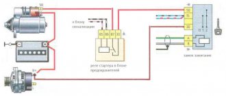
Internal combustion engines require fuel and an igniter to operate. The ignition module plays this role on fuel-injected cars.
The article will describe checking the VAZ-2114 ignition module with a multimeter.
The purpose of the ignition module (IM), operating principle, and main malfunctions will also be described in detail.
Purpose and principle of operation
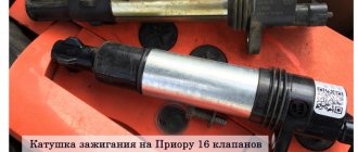
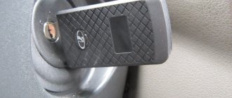
The ignition module of a VAZ-2114 car with an injection 8-valve power unit is located directly opposite the engine block on the spark plug side. This arrangement is most effective for supplying high-voltage wires to the spark plugs. The device is mounted on the wall of the engine compartment. This position was not chosen by chance. This way the MH interacts less with vibrating parts of the car.
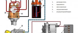
The device that comes with the described car model is of the block type. One housing contains 2 inductors and 2 discharge voltage regulators. The device operates according to the following principle:
- A pulse signal passes from the crankshaft position controller to the on-board computer.
- The signal is confirmed by a pulse signal from the Hall sensor of the ignition system.
- Both signals are calculated in the on-board computer and transmitted as current to the module.
- The module converts 12 volt voltage into high current.
- From the coil, the voltage is supplied to the spark gap, which forms a pulse voltage.
- The voltage passes through the high voltage wire of cylinders 1 and 4 to the spark plug.
- The spark plug is discharged by a spark, igniting the fuel in the cylinder.
- During the discharge, spark plugs 2–3 also receive voltage, but its power is adjusted by the spark gap.
All components are made of high-strength plastic with an aluminum plate for mounting to the engine. Additionally, both coils are filled with insulating solution. On the body of the device there are only 4 contact sockets for high-voltage wires and an electrical power socket.
Subject to all operating rules, the ignition module is a very reliable electronic device, but it is quite fragile. If the electrical circuit has a number of damages and is often subject to short circuits, then the coils or arresters fail.
Any malfunction of the MH leads to interruptions in engine operation. The following will describe the main symptoms of a malfunction of this device.
Checking the ignition module with a multitester
You can buy a multimeter at any auto store. It is inexpensive and useful for checking all electrical elements of the car. Even if you have no experience in such work, you can follow simple instructions and easily carry out diagnostics in the garage or right in the yard:
- To check the ignition module itself, you need to check the contacts going to the high-voltage wires. To do this, you need to set the device to ohmmeter mode and measure the readings. First do this on cylinders 1 and 4, and then on cylinders 2 and 3. If everything is in order, the resistance readings at each of the terminals will be in the range from 5.2 to 5.5 kOhm. If the difference exceeds 100 ohms, we can confidently say that the problem lies in the secondary winding.
- You should also check the contacts without using any devices. To do this, the engine starts, then you need to open the hood and slightly pull the body in different directions. When there are no changes in operation, everything is in order: if interruptions occur, you need to check the connections. If this does not help, most likely the reason is in the module itself. It cannot be repaired; the easiest way is to replace it.
Another option for checking functionality is to replace the unit with another from a machine in which everything works well. When friends have a car with the same ignition module, you can remove it and install it yourself, and then check the operation. If everything is normal, then you don’t have to look for reasons further.
In case of malfunctions, replacing the part will not be difficult on your own. To do this you will need a simple set of tools and following simple recommendations:
- Disconnect the negative terminal of the battery. You cannot work with the battery connected!
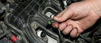
- Carefully disconnect the block with wires. There is a lock on the connector that you need to press out, and then, by shaking, pull off the chip. If it has never been removed, it may take considerable effort to get it out of place, but then everything will be quite easy.
- Carefully disconnect the high-voltage wires from the connectors. The main thing is to remember the order in which they are located so as not to get confused. You can stick pieces of paper tape and put down numbers. If the condition of the wires raises questions or they were replaced a long time ago, it is advisable to buy a new set and install it.
- The body is mounted on three studs. You need to unscrew the nuts that secure the assembly. Then gently pull it up. The new module must be installed in place and the nuts must be tightened without applying excessive force so as not to damage the plastic.
- Install high-voltage wires. To be sure, you can check the marking: it should be on the new MH. It is important to insert the end switches well into the connection so that they go all the way in and the rubber seal is pressed against the body.
After finishing the work, reconnect the battery terminal. Start the engine and make sure everything is in order. If the problem does not go away after checking the wiring and replacing the unit, you need to look for the problem among the sensors, diagnostics will help here, since it is impossible to determine the fault by eye.
Malfunctions
During the operation of the car, problems arise in the operation of the engine. They are often associated with interruptions in the ignition system. The main symptoms are as follows:
- The appearance of code P0351 indicates the absence of a spark on the spark plugs of the first stroke.
- Error P0352 indicates a lack of spark on the second stroke candles.
- Codes P3000, 3001, 3002, 3003, 3004 indicate a missed discharge to the spark plugs.
In these cases, the power unit operates with a loss of power, and stability at idle speed is lost. The engine stalls during a sharp start, or when engaging any of the gears. Heating also increases and fuel consumption increases significantly. If there is no ignition, the smell of unburned gasoline appears. It becomes almost impossible to start such an engine. Such symptoms require immediate intervention and checking the VAZ-2114 ignition coil.
Examination
Often problems with MH begin after replacing high-voltage power wires. Many people may simply make a mistake by mixing up the connection points to the candles. The pin numbering scheme is presented below.
Also, owners of the injection-type VAZ-2114 often replace the standard wires with modern silicone analogues. This is absolutely impossible to do. Silicone high-voltage wires have significantly higher resistance. When replacing, it is also important to consider the length of each wire. Standard wiring has the following parameters:
- The wire of cylinder 1 has a length of 56 cm and an operating resistance of 2.5 to 3.8 Ohms.
- A 44 cm long wire with an operating resistance of 2 to 3 Ohms goes to the second cylinder.
- 3 wire 36 cm long, resistance from 1.6 to 2.6 Ohms.
- 4 wire 32 cm long, resistance from 1.4 to 2.1 Ohm.
This is worth considering, since high resistance significantly reduces the spark discharge current.
Also, a problem with the ignition module may arise due to problems with the fuse responsible for its protection. The fuse is located behind the cover under the dash on the front passenger's side. This is the very first fuse located between relays 1 and 2. The element should be checked for the presence of a working jumper inside the housing. The test can be carried out visually, or using a tester in dial mode. Be sure to replace the burnt-out protective element with a complete analogue, rated 15 amperes. It is also worth checking the incoming voltage. This requires:
- Set the tester to DC voltage measurement mode up to 20 volts.
- Connect the red test probe to the fuse terminal.
- Connect the black probe to ground.
- Turn on the ignition.
The voltmeter should give a reading equal to the battery charge. If there is voltage, it means it is reaching the ignition module.
Module
Many owners of the car described do not know how to check the VAZ-2114 ignition module using a multimeter. First you need to test the device with the engine running. This requires:
- Start the power unit.
- Ask an assistant to keep the speed within idle.
- Wear a glove or take a dry cloth.
- Remove the power wires from the module sockets one by one.
Each removed wire must be brought to the power unit block. Without touching, a spark should discharge from the tip. A blue spark and a discharge accompanied by a crackling sound will indicate the necessary supply of discharge current. In this case, the engine should respond to the removed working wire by reducing the speed. If a wire is detected from which the spark does not come or it is quite weak, the engine speed will not change.
The previously described error codes from the on-board computer can also help in finding the wire with no spark.
For more effective testing, it is necessary to dismantle the ignition distribution device and carry out a test with a tester. This is easy to do if you follow these instructions.
First you need to dismantle the device. This is done as follows:
- Disconnect the ground terminal from the battery.
- Remove 4 high-voltage wires from the MZ sockets.
- Disconnect the electrical power plug.
- Unscrew the 3 nuts securing the module.
- Remove the device.
Next, a mandatory visual inspection of the device is carried out. The ignition module is a rather fragile device. The presence of defects on the housing, cracks and dents, can cause an internal short circuit. You also need to pay attention to the sockets for power cables. There should be no oxidation or dirt on the terminals. Any malfunctions should be eliminated by cleaning with a solvent. Next you need to check the connecting plug. Its contacts also need to be cleaned. Below is a step-by-step guide on how to check the VAZ-2114 ignition module with a multimeter.
Checking the connecting plug
First you need to check the incoming voltage to the module. This is done as follows:
- The multimeter is switched to voltmeter mode to measure DC voltage.
- The red measuring probe is connected to the incoming half of the module plug, with the central contact. It is he who is responsible for powering the device.
- The black test probe is connected to ground.
- Turn on the ignition.
The tester should show a voltage of 11.5–14 volts, equal to the battery charge.
Next, the incoming signal is checked. The voltmeter remains in the same position.
- The red probe of the tester is connected to contact “1” of the coming side of the plug. This contact is responsible for the distribution of pulse current for the cycle of candles 1–4.
- The black probe connects to ground.
- It is necessary to crank the starter a few turns.
The voltmeter should show pulse voltage. Contact “3” on the plug is checked in the same way.
Module plug
For this test, you need to switch the multimeter to resistance measurement mode. Next you need:
- Connect the red control probe to terminal “1”.
- Connect the black control probe to terminal “3”.
- The operating resistance should be within 0.5 Ohm.
In this way, both secondary windings of the ignition coils are checked. Any deviations in resistance will indicate an internal violation of the integrity of the winding.
Using the following test, the presence or absence of a short circuit is checked.
- The multimeter remains in resistance measurement mode.
- Connect the red test probe to the central contact of the plug.
- Connect the black test probe to the device body.
- The tester should not show any results. This will indicate that there is no internal short circuit. Any minimal resistance during this test is reason to replace the module.
The following check is needed to test the primary windings. The check is carried out as follows:
- The multimeter is switched to resistance measurement mode.
- Insert the red measuring probe into the “1” socket for high-voltage wires.
- Insert the black measuring probe into socket “4”.
- The operating resistance of the primary phase windings is 0.5 Ohm. Any data that differs from the nominal value can be recognized as the presence of an interturn short circuit in the primary winding of cylinders 1–4.
The test of sockets “2” and “3” is carried out in a similar way. Their operating resistance should also be 0.5 Ohm.
Additionally, you can check in the same way, but between sockets “1” and “2”. There are no internal connections between them. If there is resistance, the part is considered unsuitable for further use.
How to check the ignition coil of a VAZ
If the ignition coil is faulty, the engine will not start. A characteristic sign of a faulty coil is its increased temperature when the ignition is turned off. This is easy to determine by touch.
Signs of a faulty ignition module may include the following:
- hesitant engine starting or failure to start;
- failures during sudden changes in speed;
- high fuel consumption;
- two cylinders do not work, the engine is feverish;
- lack of dynamics;
- a sharp drop in power;
- drop in power and thrust after warming up.
These symptoms may not only be caused by the ignition module. To determine the malfunction, it is enough to spend a few minutes diagnosing spark plugs, high-voltage wires and caps. This will eliminate the remaining elements of the ignition system and make sure that it is the ignition module that is faulty.
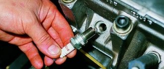
Checking the ignition coil is performed in one of 2 ways. The simplest one is to remove the central wire from the breaker-distributor, bring it to the motor housing and turn it with the starter, and a running spark should appear. After this, we check the energy supply to a separate spark plug, for which we unscrew the working spark plug, bring its contact to ground and attempt to start the engine. In this case, the spark should come from the wire to ground. If it is absent, the reason will be a malfunction of a system element such as the ignition coil.
To check the module in the second way, we only need a multimeter, then follow the step-by-step instructions:
- We check the power supply and the presence of pulses supplied from the ECU. We check the power between the central terminal (15) of the wire block connected to the module and the engine ground. When the ignition is on, the voltage should not be less than 12 V. Otherwise, either the battery is dead or the ECU does not work.
- We check the pulses from the ECU on the wiring block. We install one tester probe on connector 15, the second on the far right, then on the far left. The assistant cranks the engine with the starter, and at this time we record short-term voltage surges with a tester. If there are no impulses from the ECU, it is he who is to blame.
- We check the resistance on the secondary windings of the coils. We put the tester in resistance measurement mode and measure it at the high-voltage terminals of the module cover. Between pins 1 and 4 and pins 2-3, the resistance should be 5.4 kOhm. Otherwise, the module must be replaced.
- We check the resistance of the primary windings between contacts 15 and the rightmost, then the leftmost terminals. Nominal - 0.5 Ohm. Deviation is not allowed.
- Check the module for a short circuit. In ohmmeter mode, install one multimeter probe on the central terminal, the second on the metal body. There shouldn't be any resistance. If the device detects at least some resistance (other than unity or infinity), the module must be replaced.
Useful: VAZ cooling fan connection diagram
Other reasons
If, after checking the ignition module of an injection-type VAZ-2114 car, no malfunction was identified, then you should pay attention to breakdowns or improper operation of adjacent devices.
- Powertrain control unit. It happens that after an electrical short circuit, the ECU loses its internal settings. To restore functionality, you need to disconnect the “+” terminal from the battery and connect it again. The ECU will enter a temporary reboot, and the module's operation may be restored. It is also worth carrying out professional diagnostics of the on-board network.
- Crankshaft position sensor. An important source of pulse signals. Its data affects the distribution of voltage from the ECU to secondary devices. It is necessary to check the functionality of this element, its wiring, and the protective fuse. If necessary, replace faulty parts.
- Hall Sensor. This device is responsible for the distribution of pulses. Signals are generated due to contact connection during rotation of the device rod. Any deviations in the supply of signals affect the operation of the ignition module.
- Generator. The high charge current of this mechanism often leads to complete burnout of the secondary winding of the MC. The first problem may be a faulty fuse. If such a problem is detected, it is worth checking the amount of voltage coming from the generator.
The system, which includes a Hall sensor, DPKV and ignition module, works by calculating the position of the crankshaft. This is how the exact order of the spark cycle on the cylinders is achieved.
Important! Very often, the performance of the MH is affected by careless operation of this device. The cause of failure may be:
- Lack of contact with the “mass”. This occurs when the 3 bolts securing the device are insufficiently tensioned. Periodic loss of contact leads to a break in the circuit. The newly appeared contact causes the discharge of a current of greater strength. This leads to internal burnout of the secondary winding of the coils.
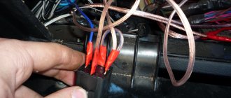
- Lack of contact on spark plug caps. A poor connection leads to contact vibration, often high-voltage wires fly out and short to ground. This leads to damage to the MZ discharge contactor.
- Poor contact or oxidation at the battery terminals. It also leads to a short-term but powerful discharge of the primary winding.
- Spark plug gap. The manufacturer sets a fixed spark plug gap. The maximum value for spark plugs installed on injection engines can be 1.3 mm. A large gap leads to a spark hitting the housing. The spark is simply deflected to the side. A small gap size can lead to breakdown of high-voltage wires or the ignition coil itself. The high voltage pulse current is simply discharged back into the circuit.
Many car enthusiasts try to disassemble and repair ignition modules themselves. With proper knowledge of electronics, only the discharge regulator can be repaired. The coils will have to be rewound. But the main difficulty lies in the subsequent sealing and insulation of the inductors. Any remaining cracks will cause breakdown and failure. It is better to purchase and replace the MZ with an exact analogue.
Methods for checking the ignition module of a VAZ 2114
There are several ways to find out if the module is working properly. Many car enthusiasts are wondering about checking the ignition module of the VAZ 2114, because there are several types of system for this model. Therefore, not each of them is suitable in structure and structure. The first of these options is quite effective and often used. First, you need to use another working module and try to start the engine with it, this will help you find out for sure whether the previous one is broken.
However, it is worth considering that there are different types of modules for a given type of car, so you need to use the one that is suitable. If the engine does not work properly with another module, then the old one needs to be replaced. If the problem is still in damaged wires, then there is a high risk of damaging another component. To prevent this situation, you need to inspect the wires for damage before checking. However, to do this, you need to know how to ring the ignition module to ensure that the wires are working properly and functioning properly.
Ignition module VAZ 2114
Using a Multimeter
All you need to do is use a multimeter that is set to voltmeter mode. After which you need to disconnect the ignition module and coil. Next, you need to carry out some manipulations with the contacts called “A” and the engine ground. Try starting the engine and look at the multimeter readings. They should not exceed 12 V. Carry out similar actions with the second contact. Other indicators besides those indicated may be the result of a malfunction or breakage of high-voltage wires. However, in some cases, the current may not flow or flow, but in small quantities because the fuse has blown.
It is worth noting that this vehicle model has three fuses that trigger the spark plugs. Therefore, to exclude this option, it is necessary to check the proper functioning of the fuses. After all, the proper operation of the engine depends on each component of the whole mechanism. However, in order to check the ignition module with a multimeter, you need to make sure that the wires through which high voltage enters the module do not contain damage or cracks. After all, this entails damage to the entire diagnostic process.
Diagnostic algorithm
Still, before checking the ignition module on a VAZ-2114, you should familiarize yourself with the algorithm of actions that need to be performed during further diagnostics . This algorithm includes the following items:
- The high-voltage circuit checks the ignition module for breaks;
- inspection and testing is carried out by tugging and tapping (a similar method is most often used by car enthusiasts to check the serviceability of parts and components of the mechanism).
In the case of the first point, take a multimeter configured to determine resistance. Since the connections in the ignition coil are parallel, the resistance that exists between them must be at a certain level. Otherwise, when the readings are different, it may mean that a break has occurred. In this situation, the model cannot be repaired and must be replaced. For the second point, such actions are the norm, despite the fact that it sounds a little not serious.
However, after these procedures, there is a possibility that the component will begin to function, albeit for a short period of time. Still, after this you need to go to a specialized vehicle store and buy a new component.
To avoid such situations, it is necessary to do regular inspection of your mobile vehicle. Also carry out checks to ensure that important engine parts, such as the ignition module, are in good working order. After all, it is thanks to him that your car starts and drives stably. Most often, specialists working in auto shops can advise clients on issues that interest them, as well as provide recommendations in the selection of parts.
It is recommended to make purchases in stores that have a reputation and directly cooperate with trusted manufacturers.