02/23/2021 11,655 VAZ
Author: Ivan Baranov
To ensure normal engine starting in any weather, many different mechanisms and elements are used. But they are all combined into one system - the ignition system (I). We will tell you more about the SZ for the Oka car below. What functions does the Oka ignition coil perform, what malfunctions are typical for SZ in general, and how to set the advance angle - read below.
[Hide]
Ignition Features
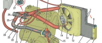
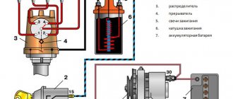
Diagram of a contactless SZ on the Oka
Before we talk about how to set and adjust the ignition on the Oka with your own hands in accordance with the diagram, let's understand the features of the SZ.
The ignition system on any car includes several different components, the main ones:
- Spark timing controller. This device is equipped with vacuum and centrifugal regulators. The device is designed to ensure the timing of spark formation, taking into account its standard installation, the number of engine revolutions, and the load on the motor. The signal reading procedure is based on the Hall effect.
- The switching device is designed to open the supply circuit of the primary winding of the short circuit, thus converting control signals into current pulses. When the ignition is activated, the connector of the switching device must not be disconnected under any circumstances, since this will lead to damage not only to this unit, but also to other elements of the SZ.
- Coil. In the ignition systems of Oka cars, in accordance with the diagram, a two-terminal short circuit with an open or closed magnetic circuit is used.
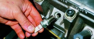
- Candles. This element is designed to transmit a high-voltage pulse, which contributes to the ignition of the combustible mixture in the cylinders of the internal combustion engine. The service life of spark plugs is about 10 thousand km, but this figure can be changed upward in accordance with the specifics of the spark plugs themselves. Or to a lesser extent, if for some reason the service life of the spark plugs is reduced.
- High-voltage cables designed to connect spark plugs to a distributor. In Oka, high-voltage circuits with distributed resistance are used. Do not touch them while the engine is running, as this may cause serious injury. It is also prohibited to start the power unit if the high-voltage circuit is broken (the wires may be broken or crushed, or the insulation on them may be damaged). If the insulation is broken, then other elements of the system may fail in accordance with the diagram.
- Egnition lock. According to the diagram, the lock is designed to start the engine by supplying voltage to an additional relay when the key is turned (video author - Nail Poroshin).
Typical system malfunctions
Among the malfunctions of the SZ, the following should be highlighted:
- Coil failure. This problem doesn't happen often, but it can happen nonetheless.
- Distributor failure. You can read more about distributor malfunctions, as well as troubleshooting, here.
- Spark plugs are worn out or have carbon deposits on them. This problem is relevant for many of our compatriots. Read about the reasons why soot appears and what ways to eliminate this problem exist in this article.
- Malfunction of high-voltage wires. The wires may be broken (broken) or their insulation may be damaged. Operating a car with such a problem is not allowed.
- Broken ignition switch. Wear on the inside of the lock will result in the driver being unable to start the engine with the existing key. Replacing the lock cylinder will solve the problem (the author of the video is Mikhail Burashnikov).
Common electrical faults
Common problems with electrical equipment on VAZ-1111 and 1113:
- Failure of external lighting devices. A common cause of failure is burnt out lamp filament; the unit must be replaced. If the light bulb is intact, then there may be a defect in the electrical wiring, due to which a short circuit occurs and the fuse fails. The fuse link is replaced with an identical one; it is prohibited to use parts designed for a higher current. It is also unacceptable to install homemade jumpers (“bugs”), as this can cause a fire. If a repeated burnout occurs, it is necessary to check the circuit and eliminate the wiring fault.
- Wire breaks occur at points where the insulation is subject to bending or friction against moving surfaces. An example of such a point is the junction of the door and the body. Damaged areas must be replaced with products made of similar material with an identical cross-section.
- Oxidation of contact surfaces due to moisture or aggressive liquids (for example, battery electrolyte). It is necessary to clean the surfaces down to metal, restoring the transmission of electric current.
- Relay failure associated with burnt contacts or coil breakage. The unit cannot be repaired; it must be replaced with a new one. In the event of a rapid re-failure, the vehicle's electrical system must be checked at a car service center.
- Sudden battery discharge is due to an internal short or current leakage. In winter, a partially charged battery may lose capacity due to low air temperatures. You need to charge the battery and check the condition of the wiring. If necessary, the power source must be replaced.
- Pulsating operation of external lighting lamps with an unusually bright glow indicates a breakdown of the relay regulator on the generator. Repair requires removing the unit and replacing failed components.
- Insufficient battery charge (the warning light does not go out when the engine is running). The cause may be wear on the brushes or commutator, or insufficient tension on the drive belt. The generator needs to be repaired, since the battery charge is enough for 150-200 km during the daytime.
- Poor contact between the ends of the cylindrical fuses and the spring-loaded elements in the mounting block. It arises due to the design features of the unit. Many owners, tired of dealing with the defect, install homemade blocks for knife inserts. Usually a short section from the GAZ-3110 is used, designed for 13 seats. There are self-assembled units designed for fuses and relays.
Photo gallery
The process of installing a new mounting block with blade elements.
Ignition installation instructions
How to set the lead angle correctly:
- First of all, you need to open the hood and remove the air filter. The angle diagnostic procedure should be carried out at idle engine speed, while the crankshaft should operate at a frequency of about 850-900 rpm. The angle itself can be deviated from TDC by no more than one degree. If it is set incorrectly, the motor may overheat, and the machine as a whole will not be able to develop the required power. Depending on the car, the problem may also cause detonation.
- To prevent the set ignition angle from leading to such consequences, you first need to align the mark on the flywheel of the internal combustion engine with the middle mark on the scale. The first mark is located on the flywheel itself, the second is on the scale of the crankshaft rear oil seal. At this moment, the piston in the cylinder will be located at TDC. When setting, keep in mind that each division corresponds to two degrees of the crankshaft gate.
- In addition, the ignition adjustment procedure can be carried out taking into account the marks located on the generator drive pulley and on the timing belt protective cover. The longest mark should correspond to the installation of the piston of cylinder 1 in the TDC position. As for the short mark, it corresponds to a five-degree advance of the crankshaft rotation.
- You need to disconnect the pipe connected to the vacuum regulator. Having done this, you can disconnect the high-voltage cable from the spark plug installed in cylinder 1. This wire will subsequently need to be connected to the strobe - before use, read the service book of the device.
- After completing these steps, you need to remove the rubberized plug from the clutch housing hatch. The luminous flux should be directed into the crankcase hatch itself. If the angle is set correctly, the mark will be between marks 2 and 3.
- Next, using a wrench, you need to loosen the three nuts that secure the spark sensor. If you need to increase the torque, then the controller should be turned clockwise, respectively, if you decrease it, then counterclockwise. When the adjustment is complete, the nuts will need to be tightened.
How it all works
The principle of operation of the ignition system is as follows: after turning the key to position “1” el. Energy from the battery is supplied to the ignition system components through the lock, fuses and auxiliary relay. In this case, high voltage pulses are not generated, since the spark torque sensor is not yet operational.
After activating the starter, the timing drive begins to rotate the camshaft, and accordingly the sensor shaft - the Hall sensor begins to interact with the screen, due to which control pulses are created.
Arriving at the commutator, these pulses interrupt the power supply circuit of the coil winding. When the power circuit is broken, a high voltage pulse is induced in the coil, which is transmitted through high-voltage wires to the spark plug, which leads to the formation of a spark between its electrodes.
Malfunctions
The simplified design of the ignition system and the absence of moving components ensures high reliability and ease of maintenance.
There are not so many malfunctions in the Oka ignition system:
Since the ignition system is directly involved in the operation of the engine, any malfunction in it immediately affects the performance of the engine - interruptions occur, the unit does not develop power, popping noises appear, or the unit simply does not start.
Diagnosis of a malfunction is carried out by visual inspection of the wiring and its connections, as well as by sequentially replacing all components with known good ones. A check using measuring instruments allows you to more accurately determine the faulty element.
The search for the problematic element is carried out from the candles. That is, first the presence of a spark is checked on them, then the high-voltage wires are inspected, and then the performance of the coil, switch, and Hall sensor is diagnosed.
The components of the ignition system are non-repairable, so if they break down they must be replaced.
Prevention measures
What you need to consider to prevent problems with electrical equipment:
- If you notice voltage surges or short circuits, immediately contact an electrician or fix the problem yourself.
- Carry out regular battery maintenance, at least twice a year. During maintenance, pay attention to diagnosing the liquid level in the cans, inspect the body for damage, and also charge the battery to replenish its discharge.
- When laying wiring, all wires must be securely insulated.
- Do not turn on the appliances, radio or heater at full power if the engine is not running. This will cause the battery to drain faster.
- Never install homemade safety devices (in the form of a jumper, wire or coin) into the fuse box.
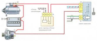
Scheme of the contactless ignition system of the OKA VAZ-1111 – 1113 car
Scheme of the contactless ignition system of the OKA VAZ-1111 – 1113 car : 1 – ignition switch relay; 2 – ignition switch; 3 – fuse block; 4 – switch; 5 – spark moment sensor; 6 – ignition coil; 7 – spark plugs.
Ignition system
– contactless.
Consists of a spark torque sensor, switch, ignition coil, spark plugs, ignition switch and high and low voltage wires. Spark timing sensor
- type 5520.3706 (until 1989, a type 55.3706 sensor was installed) with built-in vacuum and centrifugal ignition timing regulators.
It sets the moment of spark formation depending on its initial setting, the number of revolutions of the crankshaft and the load on the engine. Reading of control pulses is based on the Hall effect. There is one pulse for each revolution of the crankshaft (two for each revolution of the camshaft). The initial ignition timing angle for the VAZ-1111 engine is -1 ±1° before TDC, for the VAZ-11113 – 4±1° before TDC. The switch
- type 3620.3734, or 36.3734, or HIM-52 opens the power circuit of the primary winding of the ignition coil, converting the control pulses of the sensor into current pulses in the ignition coil.
The switch is checked with an oscilloscope using a special method; if a malfunction is suspected (interruptions in engine operation, shots in the muffler), replace it with a known good one. Do not disconnect the switch connector while the ignition is on - this may damage it (as well as other components of the ignition system). The ignition coil
is two-terminal, dry, type 29.3705 - with an open magnetic circuit, or type 3012.3705 - with a closed magnetic circuit.
Data for testing: resistance of the primary winding at 25°C – (0.5+0.05) Ohm, secondary - (11 ±1.5) kOhm. Insulation resistance to ground is at least 50 MOhm. Spark plugs - type A17DVR, or A17DVRM, or their imported analogues (with noise suppression resistors with a resistance of 4-10 kOhm). The gap between the electrodes should be within 0.7-0.8 mm (checked with a round wire probe). High-voltage wires
- type PVVP-8 with distributed resistance (2000±200) Ohm/m or PVPPV-40 with distributed resistance (2550±270) Ohm/m.
Do not touch high-voltage wires while the engine is running - this may result in electrical injury. It is also prohibited to start the engine or allow it to operate with an open HIGH VOLTAGE circuit (crushed wires) - this can lead to insulation burnout and failure of the electronic components of the ignition system. Ignition switch
- type 2108-3704005-40 or KZ813 with an anti-theft locking device, blocking against re-starting the starter without first turning off the ignition. When the key is turned to the “ignition” position, voltage is supplied to the control input of an additional relay type 113.3747-10, which, in turn, supplies voltage to the ignition coil and switch. Thus, the contacts of the ignition switch are relieved.