02/23/2021 11,655 VAZ
Author: Ivan Baranov
To ensure normal engine starting in any weather, many different mechanisms and elements are used. But they are all combined into one system - the ignition system (I). We will tell you more about the SZ for the Oka car below. What functions does the Oka ignition coil perform, what malfunctions are typical for SZ in general, and how to set the advance angle - read below.
[Hide]
Ignition Features
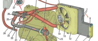
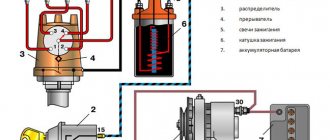
Diagram of a contactless SZ on the Oka
Before we talk about how to set and adjust the ignition on the Oka with your own hands in accordance with the diagram, let's understand the features of the SZ.
The ignition system on any car includes several different components, the main ones:
- Spark timing controller. This device is equipped with vacuum and centrifugal regulators. The device is designed to ensure the timing of spark formation, taking into account its standard installation, the number of engine revolutions, and the load on the motor. The signal reading procedure is based on the Hall effect.
- The switching device is designed to open the supply circuit of the primary winding of the short circuit, thus converting control signals into current pulses. When the ignition is activated, the connector of the switching device must not be disconnected under any circumstances, since this will lead to damage not only to this unit, but also to other elements of the SZ.
- Coil. In the ignition systems of Oka cars, in accordance with the diagram, a two-terminal short circuit with an open or closed magnetic circuit is used.
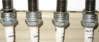
- Candles. This element is designed to transmit a high-voltage pulse, which contributes to the ignition of the combustible mixture in the cylinders of the internal combustion engine. The service life of spark plugs is about 10 thousand km, but this figure can be changed upward in accordance with the specifics of the spark plugs themselves. Or to a lesser extent, if for some reason the service life of the spark plugs is reduced.
- High-voltage cables designed to connect spark plugs to a distributor. In Oka, high-voltage circuits with distributed resistance are used. Do not touch them while the engine is running, as this may cause serious injury. It is also prohibited to start the power unit if the high-voltage circuit is broken (the wires may be broken or crushed, or the insulation on them may be damaged). If the insulation is broken, then other elements of the system may fail in accordance with the diagram.
- Egnition lock. According to the diagram, the lock is designed to start the engine by supplying voltage to an additional relay when the key is turned (video author - Nail Poroshin).
Typical system malfunctions
Among the malfunctions of the SZ, the following should be highlighted:
- Coil failure. This problem doesn't happen often, but it can happen nonetheless.
- Distributor failure. You can read more about distributor malfunctions, as well as troubleshooting, here.
- Spark plugs are worn out or have carbon deposits on them. This problem is relevant for many of our compatriots. Read about the reasons why soot appears and what ways to eliminate this problem exist in this article.
- Malfunction of high-voltage wires. The wires may be broken (broken) or their insulation may be damaged. Operating a car with such a problem is not allowed.
- Broken ignition switch. Wear on the inside of the lock will result in the driver being unable to start the engine with the existing key. Replacing the lock cylinder will solve the problem (the author of the video is Mikhail Burashnikov).
Electrical diagram of VAZ-11113 with symbols
The electrical circuit of the VAZ-11113 does not differ significantly from the VAZ-1111. The car was equipped with a modernized version of the power unit and some components that had virtually no effect on the electrics.
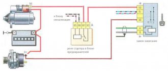
Contactless ignition diagram indicating the main elements and connecting wires
Contactless ignition VAZ-11113
- 1 - control relay;
- 2 — ignition switch with contact group;
- 3 - protective fuse;
- 4 - controller;
- 5 - sensor that determines the moment of spark supply;
- 6 - common ignition coil;
- 7 - candles.
Ignition installation instructions
How to set the lead angle correctly:
- First of all, you need to open the hood and remove the air filter. The angle diagnostic procedure should be carried out at idle engine speed, while the crankshaft should operate at a frequency of about 850-900 rpm. The angle itself can be deviated from TDC by no more than one degree. If it is set incorrectly, the motor may overheat, and the machine as a whole will not be able to develop the required power. Depending on the car, the problem may also cause detonation.
- To prevent the set ignition angle from leading to such consequences, you first need to align the mark on the flywheel of the internal combustion engine with the middle mark on the scale. The first mark is located on the flywheel itself, the second is on the scale of the crankshaft rear oil seal. At this moment, the piston in the cylinder will be located at TDC. When setting, keep in mind that each division corresponds to two degrees of the crankshaft gate.
- In addition, the ignition adjustment procedure can be carried out taking into account the marks located on the generator drive pulley and on the timing belt protective cover. The longest mark should correspond to the installation of the piston of cylinder 1 in the TDC position. As for the short mark, it corresponds to a five-degree advance of the crankshaft rotation.
- You need to disconnect the pipe connected to the vacuum regulator. Having done this, you can disconnect the high-voltage cable from the spark plug installed in cylinder 1. This wire will subsequently need to be connected to the strobe - before use, read the service book of the device.
- After completing these steps, you need to remove the rubberized plug from the clutch housing hatch. The luminous flux should be directed into the crankcase hatch itself. If the angle is set correctly, the mark will be between marks 2 and 3.
- Next, using a wrench, you need to loosen the three nuts that secure the spark sensor. If you need to increase the torque, then the controller should be turned clockwise, respectively, if you decrease it, then counterclockwise. When the adjustment is complete, the nuts will need to be tightened.
About the engine
For these models, engines 2108 and 21083 were taken as the basis. They are 2-cylinder engines with an in-line vertical arrangement of cylinders. The camshaft is installed in the cylinder head. The working volume is 649 cm 3 and 749 cm 3. The increase in volume is obtained by increasing the diameter of the pistons from 76 mm to 82 mm. The cylinder blocks of these engines, heads, flywheels, and pulleys are different.
Many spare parts are unified with their 4-cylinder variants. The power supply system is carburetor, but with changed calibration data. In 1990, the timing belt on the power unit was replaced. If the previous product had semicircular teeth, then on the new one they began to have a trapezoidal shape with a groove at the top of the tooth. The pulleys were changed to match the tooth profile, but the belts themselves are interchangeable; you can use both new and old parts.
It is possible to obtain maximum efficiency from using an internal combustion engine only with the correct adjustment of the valve timing. There are marks on the timing drive for this purpose. One of them is the protrusion on the rear cover for the drive belt protection, which should coincide with the mark on the camshaft pulley. The second mark is located at the bottom of the cylinder block, and it coincides with the mark on the crankshaft pulley. The piston of the first cylinder should be at top dead center at this time.
Preventive measures
The main measures to ensure reliable operation of the electrics of Oka cars:
- At least once every six months, clean the outer part of the battery case and check the electrolyte level (on serviced models). At the same time, it is necessary to recharge the battery using a special device. If the vehicle is rarely used, it is recommended to disconnect the terminals.
- When carrying out repair work, you should monitor the position of the wires, avoiding damage to the insulating layer. Wires passing near moving elements must not come into contact with them under any circumstances.
- It is not recommended to turn on devices with high current consumption (audio system, high beam headlights, etc.) with the engine off. This will cause the battery to drain faster.
- Do not use homemade elements to repair electrical circuits. All used parts and assemblies must comply with the standards laid down by the designer when developing the car.
- It is recommended to carry spare fuses, relays and lamps with you. This will allow you to make minor repairs if necessary.
- When carrying out repair work that requires the use of welding, it is necessary to disconnect the harnesses from the battery and generator. On machines equipped with an injection engine, it is recommended to disconnect the connector from the control unit.
Switch
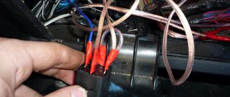
The performance of the switch can also be checked using an A12, 3 W lamp. To check, you need to disconnect the brown wire coming from terminal “1” of the switch from the ignition coil and connect the tip of the wire to the test lamp. The other terminal of the lamp is connected to the terminal of the ignition coil and the engine is cranked with the starter. If the lamp flashes when the engine crankshaft rotates, the switch generates current pulses to the ignition coil.
The described method allows only a rough assessment of the performance of the switch - whether it produces current pulses or not. Pulse parameters (magnitude and duration, shape) cannot be checked using this method. And they can seriously affect engine performance, especially at high crankshaft speeds. Therefore, the test of the switch described below on a bench using an oscilloscope and a rectangular pulse generator is more accurate.
Electrical diagram of SeAZ-11116
On SeAZ-11116 cars with a Europanel and a Chinese 3-cylinder engine, the electrics have undergone changes. The cars use an electronic instrument cluster, which has led to the emergence of a number of new sensors. The fuel supply system was changed, into which a fuel pump with a control relay was introduced. Big innovations appeared in the engine compartment, where a fuel injection and ignition control system began to be installed. At the same time, the main part of the wiring, the fuse and relay box was carried over unchanged from the old carburetor version.
Fuse diagram for VAZ-1111 and 11113
The fuse block is located at the bottom of the instrument panel on the driver's side. The unit is protected on top by a quick-release plastic cover with a spring lock. The machine uses obsolete cylindrical type fuses. A list of inserts is printed on the outside of the lid.
Fuse markings on the cover
If a fog light is installed on a VAZ-1111 or 11113, it is protected by a separate insert (nominal 8A) located on the wiring harness next to the control button.
List of fuses with a description of the protected circuits on cars with a carburetor engine:
| Number on the diagram | Denomination, A | Protected elements |
| 1 | 16 |
|
| 2 | 8 |
|
| 3 | 8 | Left side high beam and indicator lamp in the instrument cluster. |
| 4 | 8 | Starboard main beam. |
| 5 | 8 | Low beam on the left side of the car. |
| 6 | 8 | Likewise on the right side |
| 7 | 8 | Side lights on the left side (front and rear), registration plate illumination and indicator for turning on the “dimensions” (in the instrument cluster) |
| 8 | 8 | Dimensions of the starboard side, lighting system for the cigarette lighter socket and instrument cluster |
| 9 | 16 | Operation of turn signal indicators in hazard warning mode, rear window heating filaments together with the control relay |
| 10 | 16 |
|
Next to the fuse block there is a frame with five relays for the following purposes:
- turning the fan motor on and off;
- low beam activation;
- selecting high beam operating modes;
- starter engine starting systems;
- threads of electric heating of the tailgate.
External view of the relay block on the Oka car
All relays used on VAZ/SEAZ 1111 and 11113 are of the same type, which simplifies vehicle repairs in the field.
Replacing the turn signal relay is demonstrated in a video filmed by Sergey Neverov.
Proximity sensor
The functionality of the non-contact sensor located in the spark moment sensor can be checked with an indicator assembled according to the diagram shown in Fig. 152. The indicator uses MLT type resistors, 1 W; capacitor C1 is type KLS1, and capacitor C2 is type K53-14. An A12, 3 W automobile lamp was taken as an HL1 indicator lamp.
Instead of the KT816B transistor, you can use a KT814B type transistor. The indicator wires are soldered to a three-terminal block Ш1 of the same type that is connected to the spark torque sensor on a car.
To check the non-contact sensor, connect the indicator to the spark torque sensor instead of the ignition system wiring harness and crank the engine with the starter and a special key using the bolt on the crankshaft. If the HL1 lamp flashes when the crankshaft rotates, then the contactless sensor is working.
The serviceability of the contactless sensor can also be checked using a voltmeter according to the diagram shown in Fig. 154. The verification procedure is described in the next section. This method is more accurate, since it allows you to check the magnitude of the voltage pulses generated by the sensor using a voltmeter.