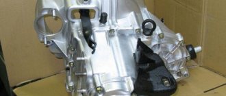
The transmission of the VAZ-2101 car consists of a manual gearbox, which transmits torque to the rear axle through a driveshaft. The gearbox itself is mechanical, 4-speed (4 forward gears and 1 reverse), three-way, with manual control (gear shifting is performed by the driver using a lever located in the car's interior). At the time of the release of the VAZ-2101, this type of gearbox was one of the highest priorities, since it ensured the least losses.
To ensure that the car moves at different speeds, each gear had its own gear ratios, which decreased as the gearbox gear increased. So, the first gear has a gear ratio of 3.753, the second – 2.303, the third – 1.493, the fourth – 1.0. The rear gear has the highest gear ratio - 3.867. The changing gear ratios of the VAZ-2101 gearbox allowed the car to move at different speeds; in 1st gear a high traction force is provided, and in 4th gear the maximum possible speed is provided.
To reduce operating noise, all gears involved in forward movement have oblique teeth, while the gears of the rear stage have straight teeth.
To make it easy to control the gearbox and change gears with minimal impact, the forward gears are equipped with synchronizers.
Cross-sectional diagram of the VAZ-2101 gearbox
is presented below (PV – primary shaft, BB – secondary, PrV – intermediate, ZX – reverse):
| 1 – gearbox pan; 2 – plug for the hole for controlling the amount of gearbox lubricant; 3 – gear of the 2nd stage PrV; 4 – gear of the 3rd stage PrV; 5 – PrV with a set of gears; 6 — bearing PrV (front); 7 – thrust bolt; 8 – washer; 9 – PrV gear (with constant clutch); 10 – synchronizer washer for the 4th stage of the PV; 11 – input shaft; 12 – crankcase front cover; 13 – oil seal; 14 – bearing PV (rear); 15 – clutch housing; 16 – housing 17 – breather of the crankcase ventilation system; 18 – PV gear (with constant clutch); 19 – explosive bearing (front); 20 – 4th stage synchronizer ring; 21 – synchronizer clutch of the 3rd and 4th stages; 22 – 3rd stage synchronizer ring; 23 – 3rd stage synchronizer spring; 24 – gear of the 3rd stage of the explosive; 25 – gear of the 2nd stage of the explosive; 26 – hub of the synchronizer clutch of the 1st and 2nd stages; 27 – secondary shaft; 28 – gear of the 1st stage of the explosive; | 29 – bushing; 30 – BB bearing (intermediate); 31 – gear ZH BB; 32 – lever rod; 33 – pillow; 34 – bushing; 35,36 – bushings (remote, shut-off); 37 — boot (external); 38 – boot (internal); 39 – lever support washer (spherical); 40 – gearshift lever; 41 – explosive seal (rear); 42 — cardan coupling flange; 43 – BB nut; 44 – seal; 45 – ring; 46 – BB bearing (rear); 47 – odometer gear; 48 – odometer drive; 49 – gearbox housing cover (rear); 50 – 3X fork; 51 – gear 3X (intermediate); 52 – gear ZH PrV; 53 – axis of the intermediate gear ZH; 54 – gear of the 1st stage PrV; 55 – magnet; 56 – plug 1 – gearbox pan; |
Design features
The VAZ-2101 gearbox diagram shows that the entire assembly consists of three shafts, which are placed in the gearbox housing. Despite the large number of components, the gearbox is relatively compact. Note that this diagram is not complete, since the sliders, latches and shift forks are not visible on it. They are located in the crankcase on the other side of the gearbox.
The input shaft receives torque from the crankshaft. To ensure the possibility of disconnecting the gearbox from the power plant, this connection is not made directly, but through the clutch mechanism. To ensure connection with the driven disk of the clutch mechanism on the first. The shaft is splined.
The primary shaft is fixed on 2 bearings. Moreover, one of them (the front one) is located in the crankshaft, and the gearbox shaft is inserted into it with its end switch. The other is located in the front of the crankcase.
At the second end of the first. The shaft has a gear, and the shaft itself is made integral with it. This gear has a constant clutch with the industrial gear. shaft To prevent oil leakage, the rear bearing of this shaft is covered with an oil seal.
Front end sec. shaft enters the primary. To eliminate axial displacement and maintain their alignment relative to each other, the secondary shaft is mounted on 3 bearings. The front one is of a needle type, installed in the hole in the front end. shaft, where the second limit switch enters. shaft
The second bearing is intermediate, it is a ball bearing and it is installed behind the 1st stage gear. The third is also a ball-shaped one, located on the back of the second. shaft in the crankcase cover.
Below these shafts there is another one - an intermediate one. At the same level with it there is a mechanism that ensures the car moves backwards.
How to change gears correctly
In order to learn how to change gears correctly , you must remember that pressing the gas pedal must be smooth; if you press the gas pedal sharply, the car can jerk forward with the tires slipping. This causes increased wear and tear, sharply increases the load on the engine, which is undesirable, and, most importantly, this behavior of the car may be unexpected for you, a novice driver, and you may lose control over the road situation.
More to read: What are the benefits for labor veterans in the Stavropol Territory in 2021
Driving in second gear must be repeated several times, practicing the skills of starting to move, changing speed and stopping the car. When your actions are brought to automaticity and a feeling of confidence comes, it’s time to master third gear.
A little about the principle of operation
The input shaft gear, as well as four industrial gears. shafts are made integral with the shafts. And only on the secondary shaft can the gears move along the shaft. This ensures the possibility of engaging the necessary gears.
In “neutral,” torque is transmitted from primary. shaft to the intermediate one through gears having constant mesh. But on the second. the shaft does not undergo this rotation, since in this position the engagement between the gears is industrial. and sec. there are no shafts.
The driver, engaging first gear, using a shift fork mounted on the slider, moves the 1st stage gear of the second through the synchronizer. shaft and engages it with the gear on the industrial. shaft
All other steps are switched on in approximately the same way. To prevent the inclusion of two stages at the same time, the driver, before turning on the required speed, first disengages the gears of the engaged stage, that is, first moves the lever to “neutral”, and then connects the necessary gears.
In order for the meshed gears of the second. the shafts have not returned to their original position due to axial force, clamps are used - special spring-loaded balls, which, once in the recesses on the slide, do not allow it to move back.
In order to ensure rotation of the second. shaft in the opposite direction (reverse movement), the design of the gearbox includes an additional intermediate axle with a gear, which is connected to the gears of the intermediate and secondary shafts using a separate fork.
In general, the entire operation of the VAZ-2101 gearbox is based on the interaction of gears of different diameters, assembled in one housing and mounted on shafts, which allows you to change the gear ratio in the desired direction.
Article on the topic
—
Bearing dimensions in the VAZ 2107 gearbox
Dimensions for parts are also regulated by law. Based on these values, the consumer can easily select the desired element. At the same time, there is a high probability of avoiding a counterfeit product, the sizes of which are often different. For the main shaft element, the diameter is set to 30 mm, the height is 19 mm, and the outer diameter of the ring is 75 mm. The number of metal balls is also determined, which make it possible to secure and ensure the mobility of the shaft itself in the amount of 7 units. A properly sized VAZ 2107 input shaft bearing is the key to long and trouble-free service of the entire unit.
Video - installation and repair of a VAZ gearbox
| 1 – bottom cover; 2 – hole plug for checking the oil level; 3 – gear II of the intermediate shaft; 4 – gear III gear of the intermediate shaft; 5 – intermediate shaft (gear block); 6 – front bearing of the intermediate shaft; 7 – bolt of the clamping washer; 8 – clamping washer of the front bearing of the intermediate shaft; 9 – constant mesh gear of the intermediate shaft; 10 – thrust washer of the synchronizer spring for the fourth gear of the input shaft; 11 – input shaft; 12 – front cover; 13 – input shaft oil seal; 14 – rear bearing of the input shaft; 15 – clutch housing; 16 – gearbox housing; 17 – breather; 18 – constant mesh gear of the input shaft; 19 – needle bearing of the front end of the secondary shaft; 20 – gear ring of the 4th gear synchronizer; 21 – sliding clutch for synchronizer of 4th and 3rd gears; 22 – blocking ring of the third gear synchronizer; 23 – third gear synchronizer spring; 24 – gear III gear of the secondary shaft; 25 – gear II gear of the secondary shaft; 26 – hub of the sliding clutch for the synchronizer of 1st and 2nd gears; 27 – secondary shaft; 28 – gear 1st gear of the secondary shaft; | 29 – gear bushing; 30 – intermediate bearing of the secondary shaft; 31 – secondary shaft reverse gear; 32 – gear shift lever rod; 33 – thrust pad; 34 – elastic bushing; 35 – spacer sleeve; 36 – locking sleeve; 37 – outer cover of the gear shift lever; 38 – inner cover of the gear shift lever; 39 – spherical washer of the ball joint of the lever; 40 – gear shift lever; 41 – secondary shaft rear bearing oil seal; 42 – flange of the elastic coupling of the cardan shaft; 43 – nut of the rear end of the secondary shaft; 44 – seal of the centering ring of the elastic coupling of the cardan shaft; 45 – centering ring of the elastic coupling of the cardan shaft; 46 – rear bearing of the secondary shaft; 47 – speedometer drive drive gear; 48 – speedometer drive; 49 – rear cover of the gearbox; 50 – reverse fork; 51 – reverse intermediate gear; 52 – reverse gear of the intermediate shaft; 53 – axis of the reverse intermediate gear; 54 – gear 1st gear of the intermediate shaft; 55 – magnet; 56 – magnetic plug |
The car is equipped with a four-speed gearbox with synchronizers in all forward gears.
The gearbox consists of a primary 11, secondary 27 and intermediate 5 shafts, a crankcase 16 and a gear shift mechanism.
The input shaft 11 is made as one piece with a gear 18 of constant mesh. It rotates on two ball bearings, the front one is pressed into the socket of the crankshaft end, the rear bearing 14 is placed in the gearbox housing and is sealed with an oil seal 13.
The secondary shaft 27 is mounted in three bearings. The front needle bearing 19 is installed in the bore of the input shaft, the middle bearing 30 is a ball bearing, pressed into the socket of the gearbox housing 16, the rear bearing 46, located in the socket of the rear cover 49, is sealed with an oil seal 41. The first gear gear 28 and the gear are freely located on the secondary shaft 25 second gear, gear 24 third gear; they are in constant mesh with the intermediate shaft gears of the same name.
At the front end of the secondary shaft there are three splines on which the hub of the sliding clutch 21 for the third and fourth gear synchronizer is located. The hub 26 of the sliding clutch for the synchronizer of 1st and 2nd gears is connected to the shaft in a similar way. Reverse gear 31 is secured to the shaft with a key. The drive gear 47 of the speedometer drive is located on the rear journal of the shaft. The flange 42 of the elastic coupling of the propeller shaft is mounted on the shaft splines and is secured with a nut 43.
The intermediate shaft 5 is made as one piece with the gear block and rests on two bearings; front bearing 6 is ball, fixed on the shaft with washer 8 and bolt 7, rear bearing is roller, cylindrical. The reverse gear 52 is located on the shaft splines.
The reverse intermediate gear 51 rotates freely on an axis 53, pressed into the holes of the gearbox housing and its rear cover 49.
The synchronizers for all gears have the same design. Each of them consists of a hub 26, a coupling 21, blocking rings 22 and springs 23. The hub is rigidly connected to the secondary shaft. A sliding clutch is located on the outer splines of the hub. The locking ring, with its inner rim, is connected to the synchronizer rim of the gear of any forward gear and is constantly pressed towards the sliding clutch.
Gear shifting is carried out using a mechanical drive, consisting of three rods 16, 17, 18 (see Fig. Gear shift drive
), on which forks 14, 15, 1 are attached, which fit into the recesses of the sliding clutches of the forward gear synchronizers. And fork 1 fits into the annular recess of the reverse intermediate gear. In the neutral and engaged positions, the rods are held by ball clamps 23, and the simultaneous engagement of two gears is prevented by a lock 19.
The gear shift lever is composite; its lower part is connected to the upper part through a damper device (items 9, 10, 11, 12). This connection allows you to remove the gearbox from the car without “unnecessary” disassembly. The gear shift lever with its head is placed in the ball joint 4 and is pressed against it by a spring 7 through a spherical washer 6. Rotation of the lever is prevented by a pin that fits into the hole in the ball head of the lever and the support 4.
↓ Comments ↓
1. Technical data
1.0 Technical data 1.1 Main overall dimensions of the VAZ-2101 car 1.2 Main overall dimensions of the VAZ-21011 car 1.3 Main overall dimensions of the VAZ-2102 car 1.4 Technical characteristics of the cars 1.5 Controls and monitoring devices 1.6 Ignition switch 1.7 Interior ventilation and heating controls
2. Operation and Maintenance
2.0 Operation and maintenance 2.1. Vehicle operation 2.2. Vehicle maintenance
6. Starting and charging system
6.0 Starting and charging system 6.1. Battery 6.2. Generator 6.3. Starter
9. Steering
9.0 Steering 9.1 Features of the device 9.2. Inspection, check and adjustment of steering 9.3. Steering mechanism 9.4. Steering rods and ball joints 9.5. Pendulum arm bracket 9.6 Possible steering malfunctions
10. Brake system
10.0 Brake system 10.1. Features of the device 10.2. Checking and adjusting brakes
VAZ 2101 gearbox diagram:
1 – reverse fork; 2 – tension spring of the gear shift lever; 3 – guide cup of the lever; 4 – ball joint of the lever; 5 – gear shift lever; 6 – spherical washer; 7 – lever spring; 8 – retaining ring; 9 – damper locking sleeve; 10 – elastic damper bushings; 11 – damper spacer bushing; 12 – damper thrust pad; 13 – gear shift lever rod; 14 – fork for selecting third and fourth gears; 15 – fork for selecting first and second gears; 16 – fork rod for first and second gears; 17 – fork rod for selecting third and fourth gears; 18 – reverse fork rod; 19 – blocking crackers; 20 – clamp cover; 21 – bushing; 22 – clamp spring; 23 – locking ball; 24 – rear cover of the gearbox; 25 – reverse light switch VAZ 2101; 26 – remote bushing for the reverse fork rod.
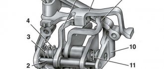
Primary shaft VAZ 2101 gearbox
The device of the VAZ 2101 input shaft:
1 – retaining ring; 2 – spring washer; 3 – bearing; 4 – input shaft; 5 – synchronizer spring; 6 – synchronizer blocking ring; 7 – retaining ring; 8 – bearing.
Secondary shaft of the VAZ 2101 gearbox
The device of the secondary shaft of the VAZ 2101:
1 – retaining ring;
2 – spring washer; 3 – synchronizer hub; 4 – synchronizer clutch; 5 – retaining ring; 6 – synchronizer blocking ring; 7 – synchronizer spring; 8 – washer; 9 – third gear gear; 10 – secondary shaft; 11 – 2nd gear gear; 12 – washer; 13 – synchronizer spring; 14 – blocking ring; 15 – retaining ring; 16 – synchronizer hub; 17 – synchronizer clutch; 18 – retaining ring; 19 – synchronizer blocking ring; 20 – synchronizer spring; 21 – washer; 22 – 1st gear gear; 23 – bushing of the 1st gear gear; 24 – bearing; 25 – reverse gears; 26 – spring washer; 27 – retaining ring; 28 – speedometer drive gear; 29 – rear bearing; 30 – oil seal; 31 – elastic coupling flange; 32 – nut; 33 – seal; 34 – centering ring; 35 – retaining ring. Backstage VAZ 2101
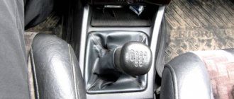
Gear shift lever structure of VAZ 2101:
1 – tension spring bolt; 2 – washer; 3 – tension spring; 4 – gasket; 5 – guide cup; 6 – gasket; 7 – washer; 8 – limit bolt; 9 – gear shift lever; 10 – ball joint; 11 – spherical washer; 12 – spring; 13 – support washer; 14 – retaining ring; 15 – gasket; 16 – flange; 17 – spring washer; 18 – nut; 19 – cuff; 20 – inner cover; 21 – lever rod; 22 – handle; 23 – thrust pad; 24 – elastic bushing; 25 – spacer sleeve; 26 – elastic bushing; 27 – locking sleeve.
How to disassemble the VAZ 2101 gearbox
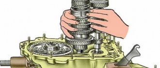
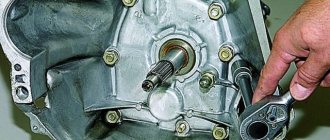
To replace parts of the VAZ 2101 gearbox, it must be partially or completely disassembled; to do this, follow these instructions: Wash the gearbox and install it on a stand. Drain the oil and remove the gearbox housing with gasket. Remove the clutch release fork, and from the guide sleeve of the front cover of the gearbox, remove the clutch assembly with bearing and connecting spring. Remove the clutch housing (bell housing) with the gasket and the front cover of the gearbox along with the oil seal and spring washer. Remove the VAZ 2101 speedometer drive with the gasket and the reversing light switch, being careful not to deform its housing. Remove the bolt securing the third and fourth gear shift fork. Install clamp 41.7816.4068 on the input shaft or engage two gears at the same time. This will prevent the primary, secondary and intermediate shafts from turning and will allow subsequent disassembly operations to be performed.
Remove the snap ring from the end of the transmission output shaft
Having straightened the lock washer, unscrew the nut a few turns to move the centering ring of the elastic coupling, and tighten the nut again. Using a puller with a puller, remove the centering ring of the elastic coupling of the propeller shaft from the end of the secondary shaft.
Remove the elastic coupling centering ring seal from the end of the secondary shaft, unscrew the nut and remove the elastic coupling flange using a puller. Remove the rear cover of the gearbox by unscrewing the nuts securing it and the screw for limiting the lateral travel of the lever, and also moving the gear shift lever to the left to free it from the gear shift rods. Remove the rear bearing from the output shaft. Remove the speedometer drive gear. Remove the fork with the spacer bushing from the reverse control rod, and the reverse intermediate gear from the axle.
Remove the retaining ring of the VAZ 2101 reverse drive gear from the intermediate shaft; Remove the gear and spring washer. Remove the reverse driven gear snap ring from the output shaft by pressing down on the spring washer with a mandrel to relieve the load on the snap ring. Remove the reverse driven gear and spring washer. Using shaped mandrels such as screwdrivers and rod drifts, remove the front and rear intermediate shaft bearings from the gearbox housing. On the inner rings of the double-row front bearing, make marks according to which these rings should be installed in their original places in the outer ring of the bearing.
Remove the intermediate shaft from the gearbox housing by tilting it as shown in the figure. Remove the rod clamp cover along with the gasket, take out the springs and clamp balls. Remove the reverse rod and the third and fourth gear shift fork rod from the gearbox housing. Unscrew the bolt securing the first and second gear forks, remove the rod and forks. When removing the rods, simultaneously remove three locking pins
Unscrew the screws securing the secondary shaft intermediate bearing locking plate using a drill screwdriver and remove the secondary shaft intermediate bearing locking plate and the reverse idler gear shaft
Using drifts, remove the input shaft along with the bearing and synchronizer ring and remove the needle bearing from the front end of the secondary shaft
Knock out the secondary shaft from the intermediate bearing of the VAZ 2101, remove the intermediate bearing and, tilting it as shown in the figure, remove the secondary shaft assembled with gears, clutches and synchronizer rings from the crankcase. Remove the third and fourth gear synchronizer clutch from the shaft.
For disassembling the input shaft of a VAZ 2101
do the following: Remove the retaining ring, locking ring and synchronizer spring. Place the shaft on the press and, squeezing the spring washer with a mandrel, remove the retaining ring, then the spring washer and the bearing.
For disassembling the secondary shaft of the VAZ 2101 gearbox
perform the following steps: Remove the first gear with bushing, the hub with the sliding clutch for shifting first and second gears, the second gear together with the synchronizer blocking ring from the rear side of the shaft
Install the secondary shaft with a mandrel on the press, place support half rings under the third gear gear, and, pressing the mandrel on the spring washer, remove the lock ring 2, then the spring washer, the hub of the sliding clutch for shifting the third and fourth gears and the third gear.
To disassemble the gear shift lever of a VAZ 2101
and the rear cover, remove the cuff, lever cover, then the lock ring, washer, spring and spherical washer. Unscrew the flange mounting nuts, disconnect the lever release spring from the bolt eye and remove the lever along with the flange, support and cup.
Repair and assembly of the VAZ 2101 gearbox is carried out in the reverse order of assembly, taking into account the replacement of old defective parts with new ones. After installing the gearbox on the VAZ 2101, be sure to fill in the transmission oil!
Click on the picture and it will enlarge
1 – bottom cover; 2 – hole plug for checking the oil level; 3 – gear II of the intermediate shaft; 4 – gear III gear of the intermediate shaft; 5 – intermediate shaft (gear block); 6 – front bearing of the intermediate shaft; 7 – bolt of the clamping washer; 8 – clamping washer of the front bearing of the intermediate shaft; 9 – constant mesh gear of the intermediate shaft; 10 – thrust washer of the synchronizer spring for the fourth gear of the input shaft; 11 – input shaft; 12 – front cover; 13 – input shaft oil seal; 14 – rear bearing of the input shaft; 15 – clutch housing; 16 – gearbox housing; 17 – breather; 18 – constant mesh gear of the input shaft; 19 – needle bearing of the front end of the secondary shaft; 20 – gear ring of the 4th gear synchronizer; 21 – sliding clutch for synchronizer of 4th and 3rd gears; 22 – blocking ring of the third gear synchronizer; 23 – third gear synchronizer spring; 24 – gear III gear of the secondary shaft; 25 – gear II gear of the secondary shaft; 26 – hub of the sliding clutch for the synchronizer of 1st and 2nd gears; 27 – secondary shaft; 28 – gear 1st gear of the secondary shaft; 29 – gear bushing; 30 – intermediate bearing of the secondary shaft; 31 – secondary shaft reverse gear; 32 – gear shift lever rod; 33 – thrust pad; 34 – elastic bushing; 35 – spacer sleeve; 36 – locking sleeve; 37 – outer cover of the gear shift lever; 38 – inner cover of the gear shift lever; 39 – spherical washer of the ball joint of the lever; 40 – gear shift lever; 41 – secondary shaft rear bearing oil seal; 42 – flange of the elastic coupling of the cardan shaft; 43 – nut of the rear end of the secondary shaft; 44 – seal of the centering ring of the elastic coupling of the cardan shaft; 45 – centering ring of the elastic coupling of the cardan shaft; 46 – rear bearing of the secondary shaft; 47 – speedometer drive drive gear; 48 – speedometer drive; 49 – rear cover of the gearbox; 50 – reverse fork; 51 – reverse intermediate gear; 52 – reverse gear of the intermediate shaft; 53 – axis of the reverse intermediate gear; 54 – gear 1st gear of the intermediate shaft; 55 – magnet; 56 – magnetic plug
{banner_content} The car is equipped with a four-speed gearbox with synchronizers in all forward gears.
The gearbox consists of a primary 11, secondary 27 and intermediate 5 shafts, a crankcase 16 and a gear shift mechanism.
The input shaft 11 is made as one piece with a gear 18 of constant mesh. It rotates on two ball bearings, the front one is pressed into the socket of the crankshaft end, the rear bearing 14 is placed in the gearbox housing and is sealed with an oil seal 13.
The secondary shaft 27 is mounted in three bearings. The front needle bearing 19 is installed in the bore of the input shaft, the middle bearing 30 is a ball bearing, pressed into the socket of the gearbox housing 16, the rear bearing 46, located in the socket of the rear cover 49, is sealed with an oil seal 41. The first gear gear 28 and the gear are freely located on the secondary shaft 25 second gear, gear 24 third gear; they are in constant mesh with the intermediate shaft gears of the same name.
At the front end of the secondary shaft there are three splines on which the hub of the sliding clutch 21 for the third and fourth gear synchronizer is located. The hub 26 of the sliding clutch for the synchronizer of 1st and 2nd gears is connected to the shaft in a similar way. Reverse gear 31 is secured to the shaft with a key. The drive gear 47 of the speedometer drive is located on the rear journal of the shaft. The flange 42 of the elastic coupling of the propeller shaft is mounted on the shaft splines and is secured with a nut 43.
The intermediate shaft 5 is made as one piece with the gear block and rests on two bearings; front bearing 6 is ball, fixed on the shaft with washer 8 and bolt 7, rear bearing is roller, cylindrical. The reverse gear 52 is located on the shaft splines.
The reverse intermediate gear 51 rotates freely on an axis 53, pressed into the holes of the gearbox housing and its rear cover 49.
The synchronizers for all gears have the same design. Each of them consists of a hub 26, a coupling 21, blocking rings 22 and springs 23. The hub is rigidly connected to the secondary shaft. A sliding clutch is located on the outer splines of the hub. The locking ring, with its inner rim, is connected to the synchronizer rim of the gear of any forward gear and is constantly pressed towards the sliding clutch.
Gear shifting is carried out using a mechanical drive, consisting of three rods 16, 17, 18 (see Fig. Gear shift drive), on which forks 14, 15, 1 are attached, which fit into the recesses of the sliding clutches of the forward gear synchronizers. And fork 1 fits into the annular recess of the reverse intermediate gear. In the neutral and engaged positions, the rods are held by ball clamps 23, and the simultaneous engagement of two gears is prevented by a lock 19.
The gear shift lever is composite; its lower part is connected to the upper part through a damper device (items 9, 10, 11, 12). This connection allows you to remove the gearbox from the car without “unnecessary” disassembly. The gear shift lever with its head is placed in the ball joint 4 and is pressed against it by a spring 7 through a spherical washer 6. Rotation of the lever is prevented by a pin that fits into the hole in the ball head of the lever and the support 4.
Both models are equipped with a four-speed gearbox, with the exception of the VAZ-21065 model, which is equipped with a five-speed gearbox and, as an option, a four-speed gearbox. Both types of gearboxes are unified according to the gear ratios of the gears of the same name.
Until 1987, the vehicles described were equipped with two types of four-speed gearboxes, differing from each other in gear ratios. On the VAZ-2106 the gear ratios were: 1st gear - 3.24; 2nd gear - 1.98; III gear - 1.29; IV gear - 1.00; reverse gear - 3.34.
On the VAZ-2103 and its modifications, as well as on modifications of the VAZ-2106 car, the gear ratios were: 1st gear - 3.75; 2nd gear - 2.30; III gear - 1.49; IV gear - 1.00; reverse gear - 3.87. In this case, the main gear ratio was 4.1.
Since 1987, all manufactured models of the classic layout have been equipped with a gearbox that is unified in terms of gear ratios and its design. The gearboxes differ only in the speedometer drives, each of which corresponds to its own final drive ratio. For external distinction, a paint mark is applied to the speedometer drive; blue - for gear ratio 3.9; red for 4.1, not colored for 4.3. In addition, there is a marking on the clutch housing (opposite the breather) indicating which car model it is installed on. For example, for a VAZ-2106 car it is marked with the number 6, for a VAZ-2105 - with the number 5, for a VAZ-2107 - with the number 7.
Basic faults
The gearbox used on the Kopeyka is structurally a fairly reliable unit, capable of handling a significant resource without any special intervention. But still there are problems with the gearbox.
The main problems with this unit are:
- Increased operating noise. This happens mainly due to wear of bearings and gears. To restore functionality, it is necessary to replace all worn elements;
- Difficulty changing gears. The reasons for this may be problems with the clutch, deformation of the gearshift lever or shift forks. Troubleshooting is carried out by replacing damaged clutch and gearbox elements;
- Spontaneous transmission shutdown. This malfunction occurs due to wear of the clamps of the sliders of the power forks. The malfunction is eliminated by replacing the springs and the clamps themselves, sliders;
- Oil leaking from the box. Leaks occur due to damage and severe wear of the box seals. Everything can be eliminated by replacing rubber elements;
Of course, there are other types of malfunctions, for example, jamming of the gearbox while driving, inability to engage or disable any gear, destruction of gears or shafts, breakdown of the gearbox housing. But such problems arise much less frequently and are mainly due to improper operation of the gearbox, as well as design defects in the component elements of the box. Elimination of any of the malfunctions is carried out on the removed box. Therefore, in order to restore the functionality of the gearbox, you must first know how to remove the gearbox on a VAZ-2101. Moreover, it doesn’t matter whether the VAZ-2101 gearbox is being repaired or replaced, it will still have to be removed.
Four-speed gearbox
The box has synchronizers in all forward gears. The primary shaft 60, closed by a cover 59, rotates in two bearings: the front one - at the end of the engine crankshaft and the rear 2 - in the socket of the gearbox housing. The shaft has two ring gears. The ring 56 with oblique teeth is in constant mesh with the gear 52 of the intermediate shaft, and the gear 7 with straight teeth is the crown of the 4th gear synchronizer. The intermediate shaft 51 is a block of four gears mounted in two bearings 43 and 53. The secondary shaft 16 is mounted on three bearings, with the front needle bearing 5 located in the socket of the primary shaft, the rear bearing 34 in the rear cover 37, and the middle bearing 19 in the gearbox housing. The secondary shaft is held against axial displacement by a plate 20. Each of the two synchronizers located on the secondary shaft consists of sliding couplings 9 and 45, a hub 10, locking rings 12 and springs 13. The hub, rigidly connected to the secondary shaft, has external rims on which it is located sliding clutch 9. The locking rings, with their internal rims, are connected to the synchronizer rims of the input shaft and gear 14 of the 3rd gear. The rings are pressed against the conical surfaces of the coupling by springs 13. The reverse intermediate gear 41 is freely located on the axis 42. When reverse gear is engaged, gear 41 meshes with gears 40 and 21.
The gears are switched using a mechanical drive consisting of three rods on which forks are attached, which fit into the grooves of the sliding clutches 9 and 45 of the synchronizers, and forks 39, which fit into the groove of the intermediate gear 41 of the reverse gear. In the neutral and engaged positions, the rods are held by ball detents, and disabling two gears at the same time eliminates the lock. The gear shift lever with its head is placed in a ball joint and is raised to it by a spring. Rotation of the lever is prevented by a guide pin that fits into the hole in the ball head of the lever and the support.
Perfect gear shifting
transmissions are becoming increasingly common.
.
In terms of their technical characteristics, they have long been not inferior to their mechanical counterparts, in addition, attracting the potential owner by the absence of the need to independently control the process of switching gears
, making many gestures over and over again. However, on the secondary market in the middle price segment the ratio of cars sold will still be rather, in favor of those who have a manual transmission.
While driving, these speed ranges are “erased”; practice shows that, starting from second gear, switching occurs differently. The fact is that the power of new cars can allow its owner to reach an acceleration of 70 km/h even in second gear, however, this is too ill-considered a step, since it is too costly. Most drivers switch to fifth gear when the speed exceeds 110 km/h, although it is recommended to do this already at 90 km/h. The car owner, naturally, must know about the standards, but change speed based on the capabilities of the car and. So, proper gear shifting comes down to one thing - smoothly squeezing the clutch mechanism and quickly changing gears. 21 Dec 2021 marketur 354
Share this post
- Related Posts
- How long does it take for the outlet to return the money for an item purchased on credit?
- Relief on property tax for organizations Samara
- Take the money irrevocably
- Abstract to the topic marriage contract
Five-speed gearbox
Created on the basis of a four-speed gearbox in order to maximize the unification of parts. In appearance, it differs from a four-speed gearbox in the shape of the rear cover, in the cavity of which the fifth stage is located at the end of the secondary shaft. Most of its parts are interchangeable with the four-speed gearbox. What is different is secondary shaft 1, at the rear end of which the fifth gear parts are located. The intermediate shaft 25 differs in that at the rear end there is a threaded hole for a bolt 22 securing the block 23 of the fifth gear and reverse gears. Changes have also been made to the gear shift drive: a gear selection mechanism has been introduced and the rod and fork for selecting fifth gear and reverse gear have been changed. The gear selection mechanism prevents accidental engagement of reverse gear when engaging 5th gear. It consists of a guide plate 2 of the gear shift lever, upper and lower washers 1, housing 3 of the lever 9, and reverse locking brackets 12. The listed parts are secured with three bolts that secure the gear selection mechanism to the socket of the rear gearbox cover. In the grooves of the guide plate 2, spring-loaded guide bars 14 are installed, between which the lower end of the gear shift lever is clamped. Under the action of the springs of the guide plates, lever 9 is installed in the neutral position, in which the end of the lever is located in the groove of the head of the shift rod for third and fourth gears. When engaging 5th gear, if the lever crosses the neutral position line, the protrusion of the lever rests against the bent petal of the locking bracket 12, and further movement of the lever in the direction of engaging reverse stops. To engage reverse gear, press the lever down so that the protrusion of the lever drops below the locking bracket petal.
Replacing the gearbox on a VAZ 2101-VAZ 2107
Depending on the location of the structure, the methods of carrying out repair work within the system also differ. To implement them, the owner will need a lift, a set of keys, various types of screwdrivers, a hammer, and a small knife.
The procedure for removing the VAZ 2107 input shaft bearing occurs in several stages:
- Place the car in neutral gear and disassemble the casing and gearshift knob system.
- Then it is necessary to remove the starter, since it interferes with access to the box body, and also remove the oxygen sensor and the connection between the catalyst and muffler.
- After this, move the box and begin dismantling the bearing itself. To do this, you need to remove part of the housing with a screwdriver and pry off the bearing housing itself in the core.
- Using forward movements, begin to pull out the part until it stops, and then help by hitting the screwdriver body with a hammer, slowly turning and removing the part from the standard mount.
The secondary shaft also requires several disassembly steps:
- After dismantling the gearbox, it is necessary to separate the part of the housing that hides this bearing on the secondary shaft.
- After this, you should use a special puller key to rotate the part around its axis, while you can use levers in the form of large keys, and also pry the part with a knife or screwdriver.
For the intermediate shaft, the situation is similar to the actions with the input shaft, since there are no big differences in the structure and fastening of this part. Also, by applying progressive blows of a hammer and slowly rotating the part around its axis, the unit is removed from the standard mount.
As basic advice, we can give a recommendation on the selection of replacement units. Foreign products are not always superior in quality to Russian products, which are made according to strict state standards. Therefore, you should not focus on cost when purchasing. Also, when working to change these parts, it is necessary to strictly follow the sequence of actions.
For ease of use, you should always use a lift or pit in the garage. This will make it possible to carry out not only operations to replace parts, but also preventive maintenance of other gearbox elements and the general condition of the gearbox
Also, close attention should be paid to the moment of centering and tightening of parts. In case of increased load, the bearing life decreases in proportion to the increased load and, accordingly, the next replacement will be required at shorter mileage
Lada 2107 — › Logbook › Replacing the gearbox lever repair kit
Removed the decorative cover Removed the boot (pulling it up) The process of removing the lever. I picked up the locking sleeve with an awl and thereby took it out of the groove on the lever rod and removed the lever rod. The process of removing the old repair kit. Using two screwdrivers, I carefully opened the petals of the spacer bushing and removed it, and then the elastic and locking bushings.
Parts of the gear shift lever: 1 - tension spring bolt; 2 — washer; 3 — tension spring; 4 - gasket; 5 — guide cup; 6 - gasket; 7 — washer; 8 — limit bolt; 9 — gear shift lever; 10 — ball joint; 11 - spherical washer; 12 - spring; 13 — support washer; 14 — retaining ring; 15 — gasket; 16 - flange; 17 — spring washer; 18 - nut; 19 — cuff; 20 — inner cover; 21 — lever rod; 22 — handle; 23 - thrust pad; 24 - elastic bushing; 25 — spacer sleeve; 26 — elastic bushing; 27 - locking sleeve