- How to install the euro button?
- Replacing the column casing
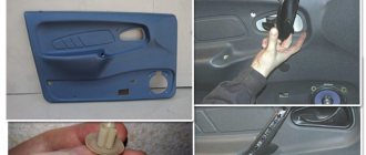
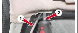
The original, factory-installed emergency lights of the VAZ 2114 are the subject of outrage among many motorists. The reason here lies in the fact that it is not installed in its usual place - on the panel, but is mounted on the side of the steering column casing.
This arrangement makes it much more difficult to quickly use the button while driving (for example, to say “thank you,” which is common for most drivers). It is for this reason that many are thinking about transferring it.
New hazard warning button
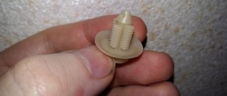
It should be noted right away that the emergency warning button of the VAZ 2114 has non-standard dimensions, as a result of which it will not be possible to simply move it from the steering column to the Euro panel - it simply will not fit. And on the casing itself, in the place where the button was located, there will be a large hole.
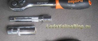
It is for this reason that replacement should be performed in this order:
- dismantling the original emergency gang;
- dismantling the column casing;
- installation of a new casing;
- connecting the new euro button to the network;
- mounting the button on the panel.
We will consider each of these operations in more detail, as well as the materials required to perform them, below.
Complete electrical diagram of the VAZ 2114 with decoding
The complete package of electrical equipment of the VAZ 2114 can be divided into two types. The fundamental differences are due to changes in equipment depending on the year of manufacture and equipment of the car. In this case, the entire drawing can be divided into several zones.
- The engine compartment is responsible for providing voltage to sensors and instruments located directly inside the engine compartment.
- Salon compartment. The part is primarily used to connect the front and rear compartments.
- Instrument panel assembly. The pinout is displayed directly on the controls and dashboard. All elements of the on-board network are combined here and connected to buttons or indicators.
- Stern joint. The small module combines chain elements located at the rear of the machine. Typically, the segment is subject to frequent damage, which is due to the constant transportation of goods in the luggage compartment. When moving over obstacles, loads can damage sensitive equipment.
You can also separate small units – these are door units, windshield wipers and others. For ease of perception, each beam is considered separately.
VAZ 2114 instrument panel pinout
The terminals of all vehicle equipment are concentrated here. Due to the fact that the unit is located under the dashboard and is subject to constant condensation or fogging, some users treat it with hot melt adhesive. Even a thin coating can reliably protect the device from water ingress.
Elements are connected to devices or controls:
- 1 – switch key for heated rear glass;
- 2/6 – fog light switches, for rear/front module;
- 3 – plastic block for activating head optics and turn signals;
- 4 – fuse block;
- 5 – wiper mode switch;
- 7 – on-board system indication;
- 8 – supply voltage to the additional harness;
- 9 – dashboard;
- 10 – “male” for powering the on-board computer;
- 11 – terminal to the ignition device;
- 12 – for door wiring;
- 13/14 – fuses;
- 16 – ignition break;
- 17 – stove motor;
- 18 – secondary resistance of the stove;
- 19 – current supply to the ignition unloading relay;
- 20 – protective relay for rear fog lights;
- 21 – starter fuse relay;
- 22 – remote socket for a portable lamp;
- 23 – power supply for the cigarette lighter;
- 24 – for illumination of the glove compartment;
- 25-27 – illuminators;
- 28 – stove switch;
- 29 – tidy lighting with rheostat;
- 30 – stop switch;
- 31/32 – horn/hazard warning switch, respectively;
- 33 – backlight of the stove panel;
- 34 – fuse;
- 35 – protective relay for seat heating elements;
- Ш1/4 – mounting block jumpers;
- X1/2 – dashboard controls;
- A – protective ground output (usually black).
Replacing the column casing
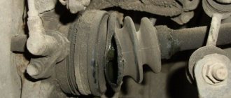
As already mentioned, when removing the old button from the steering column housing, a large hole remains in the latter. Of course, it will not interfere with the operation of the machine, but it is still better to replace the casing.
Replacing the column casing
When choosing a new one (and you will have to select it from other VAZ models), you should consider the following points:
- presence of all necessary holes for control elements;
- their location;
- the size of the hole for the steering wheel (for example, on the casing for Kalina it is very large).
The optimal one, according to the reviews of car enthusiasts themselves, is a standard casing (not “euro”!) for the 10th model.
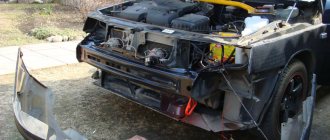
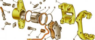
Electrical equipment of the front of the car
The following is a breakdown of the front cable bundle, excluding fog lights:
- 1 – output terminals of the starter contact group;
- 2 – battery, connection of power cables;
- 3 – standard “father” of the generator;
- 4 – blocks for connecting the power conductors of the battery and generator to the front assembly of electrical equipment;
- 5 – part of the fuse mounting block;
- 6 – standard horn;
- 7 – sensor that measures the temperature of antifreeze in the power plant;
- 8 – standard sensor for measuring the washer fluid residue in the tank; when activated, the corresponding indicator on the device lights up;
- 9/10 – left and right headlights, respectively;
- 11 – external thermometer;
- 12 – standard reverse gear lamp switch;
- 13 – drive of the electric fan of the generator;
- 14 – connector to the ignition system module;
- 15 – in the VAZ 2114 scheme the injector is not used, it is used only for the carburetor;
- 16 – electronic brake fluid level sensor; in case of a critical drop, an exclamation mark lights up on the instrument panel;
- 17 – built-in oil level sensor in the crankcase compartment of the power plant; when activated, the red light on the instrument panel lights up;
- 18 – similar for the engine cooling system;
- Ш5-8 – mounting block connectors;
- A1/2, B1/2 – grounding terminals.
Lighting devices
7.18.
Scheme for switching on headlights and fog lights: 1 – block headlights; 2 – mounting block; 3 – headlight switch; 4 – ignition switch; 5 – external lighting switch (fragment); 6 – fog lamps in the internal rear lights; 7 – fog light switch with control lamp; 8 – indicator lamp for high beam headlights in the instrument cluster; K8 – headlight high beam relay; K9 – relay for low beam headlights; A - the order of conditional numbering of plugs in the headlight block; B - to power supplies To turn on the headlights, relays of type 90-3747-11 or 904.3747-10 are used, installed in the mounting block. The same relays are used to turn on the sound signal, heated rear window and the electric motor of the engine cooling fan.
The relay switching voltage at a temperature of (23 ±5) °C is no more than 8 V, and the winding resistance is (85 ±8.5) Ohm.
The headlight switching circuit is shown in Figure 7.18. The high and low beam headlights are switched on using auxiliary relays K8 and K9. The control voltage to the relay windings is supplied from the headlight switch 3 if the right button of the external lighting switch 5 is pressed.
Regardless of the position of the switch keys 5, you can briefly turn on the high beam headlights by pulling the headlight switch lever 3 towards you. In this case, voltage is supplied to contact “30” of switch 3 from contact “30” of ignition switch 4.
7.19. Scheme for switching on fog lights: 1 – fog lights; 2 – relay for turning on fog lights; 3 – mounting block; 4 – switch for fog lights with a control lamp (on the left) and a backlight lamp (on the right); 5 – external lighting switch (fragment); A - to power supplies; B - to the instrument lighting regulator
On cars in a variant version, fog lights can be installed in the front bumpers. The diagram for switching on fog lights is shown in Figure 7.19. The headlights are turned on by switch 4 using auxiliary relay 2 type 113.3747-10 installed in the engine compartment on the left mudguard. The fog lights can only be turned on if the exterior lighting is switched on with switch 5.
7.21. Scheme for switching on direction indicators and hazard warning lights: 1 – direction indicator lamps in the headlights; 2 – mounting block; 3 – ignition switch; 4 – alarm switch; 5 – side direction indicators; 6 – direction indicator lamps in the external rear lights; 7 – instrument cluster with turn signal indicator lamps; 8 – direction indicator switch; K2 – relay-interrupter for direction indicators and hazard warning lights; A - to power supplies
The diagram for switching on the direction indicators and hazard warning lights is shown in Figure 7.21. The turn indicators on the right or left side are turned on by switch 8. In emergency mode, switch 4 turns on all turn indicators. The blinking of the lamps is ensured by the relay-breaker K2 in the mounting block.
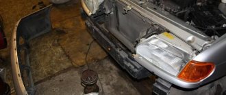
The domestic car VAZ 2114 (Samara-2) is built on the VAZ 21093 platform and is an improved version of it. The interior features a new instrument panel, a new steering wheel, an adjustable steering column, power windows and a new heater. All diagrams are taken from open sources and are intended to help in self-repair of the electrical equipment of this car. Enlarge images by clicking. The VAZ 2114 fuse box is located in the passenger compartment under the dashboard. When checking the electrical circuit of a VAZ-2114 car, you cannot check the serviceability of the circuits for a “spark” - this can lead to burnout of the current-carrying paths of the mounting block.
Wiring diagram VAZ 2114 injector: decoding of rear harness contacts
Here are the conclusions of the equipment located in the rear of the vehicle:
- 1 – output of the mounting unit;
- 2 – windshield heater;
- 3 – electric drive of the rear wiper gearbox;
- 4 – diodes for illuminating the stern license plate;
- 5 – license plate illuminator directly, some users connect diode strips here for better lighting;
- 6/7 – illuminated direction indicators, for the left and right sides, respectively;
- 8 – lamp for individual illumination of useful space;
- 9 – interior lighting lamp, usually located in the ceiling, above the steering seats;
- 10 – handbrake lever position indicator;
- 11/12 – left and right side lighting lamp;
- 13 – power supply to the additional brake light indicator;
- 14-17 – group of interior lighting switches located in the door pillars;
- Ш9 – terminal block of the fuse mounting device;
- A1 – license plate grounding;
- A2/7 – standard grounding points.
Recommendations
Comments 50
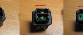
The other day I installed the same button from VAV-21123. I didn't connect the indicator. The wiring marked “Dimensions” is also not connected anywhere, but the emergency lights are working (all turn signals and repeaters are blinking, the arrows on the dash are blinking, the light in the button is blinking, there is a clicking sound). What is this wiring for (“Dimensions”)?
Then some miracles began. The day before yesterday the following happened several times: arbitrary single clattering of the turn signal while driving (the sound was heard, but I did not notice whether the turn indicator (arrow) was blinking), as well as some kind of grinding noise (as if it was shorting) after turning off the turn signal (had to several times pull the handle back and forth to make it disappear). This happened several times.
Yesterday all this no longer happened, but on one of the turns the car simply passed out - it stalled, but continued to roll. Turned the ignition off and on - it started and drove on. Today this happened again while overtaking, blinking in the other direction. It feels like it was switched off when the turn signal was turned on.
Read more: How to distinguish lamb from dog
Whether all these events are related to the installation of a new button, or whether it was a coincidence, I don’t know, but it’s disturbing in any case.
>> What is this posting (“Dimensions”) for? In order for the button illumination indicator to glow green when the side lights are turned on)) Most likely a coincidence (I’m talking about a stalled engine). But what is clicking... maybe something is wrong with the relay or the power supply to pin 13 of the relay.
Since then there haven’t been any more such quirks - apparently the button has caught on