04/10/2021 3,161 Sensors
Author: Ivan Baranov
The braking system of modern cars is equipped with an anti-lock braking system, which reduces the braking distance and allows you to drive the car in a sharp deceleration mode. To check the ABS sensor, you can use a tester, an oscilloscope, or perform diagnostics without instruments.
[Hide]
Symptoms of a problem
To monitor the operation of the system, there is a yellow or orange indicator light. In normal conditions, when the ignition is turned on, a lamp on the instrument cluster is activated, then self-diagnosis of system elements is carried out and the icon automatically goes out.
Signs of breakdown of ABS system elements:
- turning on the system warning lamp while driving;
- stable wheel locking during heavy braking;
- absence of sounds indicating ABS operation (brake pedal vibration);
- the appearance in the memory of the electronic system of error codes related to the ABS.
If signs of ABS malfunction appear, operation of the vehicle is prohibited. The brakes, designed to work together with the anti-lock braking system, do not work correctly when it is turned off.
Symptoms of a device malfunction
Despite the fact that the presented device is, as a rule, designed for uninterrupted operation over long-term operation, various types of failures and malfunctions may occur during their operation.
To visually monitor the operation of the system, use the emergency lamp on the vehicle's instrument panel. It is he who first of all points to various kinds of system disturbances caused by a number of factors.
A cause for concern in this case may be that the warning light does not go out for a long time after the key is turned to the short-circuit position, or there is no warning while driving.
The problems that caused this behavior of the sensor can be very diverse.
This is interesting
: Why the oil pressure light is on at idle and what to do
Let's consider a number of signs that will further help identify the cause of the failure of a particular system node:
- The ABS light on the instrument panel stays on for a long time or does not go out at all;
- excessive force when pressing the brake pedal;
- the brake pedal stops responding to its pressing;
- Wheels blocking when the brake pedal is pressed sharply.
ABS systems of earlier versions, as a rule, were not equipped with specialized indication of system operation. In this case, its role was played by the check engine light.
Sensor types
There are two types of sensors on cars:
- passive sensor built on the basis of a coil;
- active sensor that uses the Hall effect.
The passive sensor turns on after the start of movement and reads data from the toothed pulse ring. The passage of a tooth past the device causes the generation of a current pulse, which is read by the control unit. The sensors start working at speeds above 5 km/h and do not respond to contamination.
The active sensor consists of electronic components and a permanent magnet, which is mounted on the hub. When the magnet rotates in the device, a potential difference arises, which is formed into a microcircuit control signal. The information is then sent to the block. Sensors of this design are rare and cannot be repaired.
Sensor check
If the abs sensor is faulty, it does not transmit the necessary commands to the system and the automatic braking system ceases to perform its functions: when braking, the wheels lock. If the message on the dashboard lights up and does not go out, then you need to urgently contact service.
The induction type sensor is an induction coil that works in tandem with a toothed metal disk located on the wheel hub. Often the cause of the malfunction is a broken wire. It is this fault that we determine using a tester, a soldering iron and pins for repair. The pins are connected to the connectors and the tester measures the resistance of the abs sensor, which must be within the limits specified in the operating manual. If the resistance tends to zero, then this indicates the presence of a short circuit. If it tends to infinity, then there is an open circuit.
Then the wheel is checked and the resistance is checked, it must be changed, in this case the sensor is working. If breaks are found during inspection, they must be repaired. Breaks should be connected only by soldering, not twisting, to avoid new breaks, oxidation, etc. Each device has its own marking, wire color and polarity. We must adhere to these data.
If the sensor is broken, you need to figure out how to remove the abs sensor and replace it. When choosing a device, you must first of all focus on quality.
To fully diagnose the sensors, you must not only check the contacts of the device itself with a tester, but you should also ring all its wiring. One of the reasons for incorrect operation is a violation of the integrity of the wiring. If the devices are working properly, then the resistance indicators are as follows:
- leg – front right abs sensor (7 – 25 Ohm);
- insulation resistance level – over 20 kOhm;
- leg – rear right abs sensor (6-24 Ohm).
Many cars have a self-diagnosis system. They display error codes on the information screen, which can be deciphered using the operating instructions.
Checking ABS sensors with a tester
The car owner can check the condition of the sensors independently. This will require a few minutes of time and a simple tester. In order to check the sensor with a multimeter, you need to know the resistance value of a working coil. The measurement is made by removing the device or by disconnecting the plug connector.
Self-testing is carried out according to the following algorithm:
- Place the car on a level surface or a lift. Ensure reliable fixation against accidental movement.
- To make access to the sensor easier, it is recommended to remove the wheel.
- The wire is laid along the wheel arch and connected to the general wiring using a plug, which must be carefully disconnected. If the plug is covered with a layer of dirt, then it must be removed and the connector pads should be wiped with a clean rag. If the rear wheel sensors are checked, the connecting plugs are located in the vehicle interior. To access the plug, you need to fold back the seat cushion and peel back the carpet. On some cars, you will need to peel back the soundproofing mats located under the carpet.
- Switch the multimeter to ohmmeter operating mode.
- Connect the sensor leads to the multimeter probes and measure the resistance. Compare the value with the standard values available in the operating instructions. If such information is not available, then the readings are taken from reference literature. Usually a resistance of 0.5-2 kOhm is considered normal.
- Ring the sensor wiring harness to check for a short circuit.
- Check the operation of the sensor. To do this, rotate the wheel and look at the ohmmeter readings. Depending on the rotation speed, the resistance will change.
- Switch the measuring device to the “voltmeter” operating mode.
- Rotate the wheel at a frequency of about 1 rpm, while checking the voltage value. According to standards, it should be in the range of 0.25-0.5 Volts. As the speed increases, the voltage increases.
- Check all sensors using the procedure described above. It must be remembered that the devices on the front and rear axles differ in design and have different resistance.
Measuring resistance with a multimeter
Based on a certain resistance value, you can draw a conclusion about the state of the sensor:
- the resistance is below the permissible level - sensor malfunction;
- the resistance is close to or equal to zero—turn-to-turn short circuit in the sensor coil;
- variable resistance that changes when the position of the wiring harness changes - breaks in the wires inside the cable;
- the resistance value tends to infinity - wire or coil breaks.
If it was not possible to find out the resistance value of a working ABS sensor, you need to measure the remaining devices. A device with parameters noticeably different from the others is most likely the cause of the ABS malfunction.
Additionally, you should use a tester to check the integrity of the wiring harness from the sensor plug to the block on the control unit:
- Disconnect the connectors from the sensors and control unit.
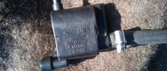
- Find information about the pinout of the control unit plug. The pinout can be found by the valve body model, which is printed on the housing identification plate.
- Ring the wiring harnesses.
Checking the ABS sensor for functionality
What is an ABS sensor for and how to detect its failure
The main function of the anti-lock braking system (ABS) is to prevent the car from “sliding” with the wheels locked on the brakes. To do this, the system monitors the rotation of all wheels and alternately increases or decreases the pressure in the entire braking system if the driver attempts to stop suddenly. A special sensor is installed in each wheel, in the hub assembly. It transmits wheel speed data to the anti-lock braking system control unit. A malfunction of this element can lead to failure of the entire system. Therefore, it is important to know how you can check the performance of the ABS sensor in the field.
Operating principle
At the moment of sudden braking, when the driver, by inertia, presses on the brake pedal without releasing it, instead of constantly blocking the wheels, the anti-lock braking system alternately blocks and then resumes their rotation. This braking system is much more effective than completely locking the wheels. And the system operation algorithm is as follows:
- A modern multi-channel ABS control system monitors the rotation speed of all wheels through built-in sensors. The electronics are activated in the event of emergency braking. When the wheels are locked, the control unit releases the pressure of the brake disc for a short period of time and rotation continues. This cycle continues until the car comes to a complete stop.
- If any of the sensors is faulty, the system will not be able to track and compare wheel speeds. In this case, the ABS will not perform its main function.
- The functioning of modern sensors is based on the rule of electromagnetic induction. At the moment the wheel rotates, another wheel rotates along the sensor - a gear wheel mounted on the brake disc. The sensor tracks which element moves past it: protruding teeth and depressions. As a result, an electrical signal is generated at the sensor coil. Depending on its frequency, the ABS control unit decides whether to start working.
- At the moment when the wheel is blocked, the ECU receives a signal from the sensor about a fixed amount of electrical resistance between the gear and the sensor itself. If this control is faulty, the ABS stops functioning.
Sensor failure rates
The following points may indicate the need to check ABS sensors:
- a light is on on the panel indicating a problem with the ABS;
- there is no “recoil” from the pedal at the moment of braking;
- During emergency braking, the car continues to “slide” along the road and risks skidding.
If one or more sensors fail, a light on the dashboard, in addition to the ABS failure indicator, will light up indicating that the handbrake is on. Information about an error in the brake system may also be displayed. In this case, the car can be used further without the ABS system. And in case of emergency braking, as drivers with good experience used to do, press the pedal sharply and intermittently, simulating the operation of electronics.
How to check using an oscilloscope and adapter
Testing with an oscilloscope allows you to more accurately test the sensor for functionality. The oscilloscope shows graphs of changes in the signal generated by the device. The sensor can supply pulses that comply with the standards, but the amplitude of the signal will be incorrect and will cause an ABS operation error. The test is performed on the car, without removing the sensor.
In order to check the ABS sensor with an oscilloscope, you must:
- Disconnect the sensor plug by analogy with the procedure used when measuring parameters with a tester.
- Connect an oscilloscope or oscilloscope to the sensor pins.
- Start rotating the hub through the wheel or other method at a frequency of 2-3 rpm.
- Record the signal oscillation curve.
- Carry out a similar procedure with the sensor located on the other side of the axis.
The serviceability of the sensor is indicated by:
- identical amplitude of oscillations of signals from sensors located on the left and right sides of the same axis;
- uniformity of the curve, without noticeable lateral deviations;
- amplitude stability in height, which should not exceed 0.5 volts.
Another way to measure parameters is to connect a laptop equipped with a special adapter. The device connects to a USB port and transmits signals to the corresponding software.
Sample USB Oscilloscope
The oscilloscope and adapter are highly specialized devices and are rarely used for personal use. The equipment is used in service stations.
Signs of sensor malfunction
The following symptoms indicate that the ABS sensor needs to be checked:
- when braking sharply or on a slippery road, the car moves “skid” and goes into a skid;
- there is no characteristic sound of ABS activation - frequent tapping or crackling from the side of a locked wheel (the type of noise depends on the make of the car);
- The anti-lock braking system warning light on the dashboard lights up.
If, for various reasons, the functionality of several sensors is disrupted, then the indicator for turning on the handbrake or a malfunction of the brake system additionally flashes on the instrument panel. You can continue to operate the car, but in slippery areas or during an emergency stop, the driver will have to work instead of ABS - often and sharply press the pedal.
Checking the sensor without instruments
The most crude way to check the health of the sensor is to test the magnetic field created during operation of the device. To do this, a steel object is applied to the sensor, which should be attracted when the ignition is turned on.
It is possible to visually inspect the device for cracks in the housing or noticeable breaks and oxidation in the wiring. It is recommended to inspect the plug and the condition of the contacts in it; oxidation is the cause of deterioration in signal conductivity.
DIY ABS diagnostics
The very first sign of a malfunctioning ABS system is a light on the dashboard. After it lights up, it is important to immediately make a diagnosis. Let's consider the actions that need to be taken if the ABS malfunctions:
- Check the fuses and relays of the anti-lock braking system control unit.
- Compare the tire pressure - it should be the same everywhere.
- Examine the rotor of each sensor for contamination.
- Use a tester to measure the resistance in each of the sensors with the ignition on. Lift the wheel on a jack and rotate it and observe the changes.
- Check the integrity of the wires coming from the sensors to the control unit.
- Check the integrity of the wires going to the ABS hydraulic unit.
The best diagnostic option would be to check by connecting a laptop or smartphone to the diagnostic connector - this will save a lot of time and instantly determine the cause of the breakdown.
How to fix problems
After checking with instruments and identifying the faulty unit, you can begin repairs. Some owners repair the sensors by replacing the wiring harness or rewinding the coil.
Sensor failure
A faulty passive type sensor can be repaired yourself:
- Remove the sensor from the hub. The fastening bolt often becomes sour, so you should unscrew it carefully. For removal it is allowed to use WD40 type fluid.
- Remove the protective coil housing. Removal is done with a file. The cut should be done extremely carefully so as not to damage the housing and winding.
- Remove the protective film from the winding by prying it off with a sharp knife.
- Carefully unwind the wire from the spool. During the removal process, the version of a conductor break is confirmed. As a result, you will be left with an empty ferrite core, resembling a spool of thread in shape.
- Wind a new winding. Copper wire from the coils of common relays of the RES-8 type can be used as a conductor. Winding can be done using a drill with smooth speed control. Be careful as breaking the wire will return you to the start. It is recommended to wind the conductor to the top level of the coil.
- Check resistance. Most coils have a value in the range of 0.9-1.2 kOhm. To clarify, it is recommended to measure the parameter on a known-good sensor located on the opposite side of the axis. The resistance is adjusted by unwinding the excess wire. If the reading is low, you will need to use another wire or re-wind. Secure the wire from unraveling with tape or other adhesive tape.
- Solder the wires to the coil terminals that serve as a connection between the winding and the harness. For outputs, it is recommended to use multi-core insulated cable, which has increased strength.
- Install the coil into the old housing. If it received significant damage when disassembling the device, then the coil is filled with epoxy resin. To do this, the part is located in a metal container of a suitable size, for example, a capacitor housing. The air gap between the coil and the glass is carefully filled with resin. When pouring, it is advisable to avoid large air voids. After the resin has completely hardened, the body is removed.
- Reinstall the sensor mount, securing it with epoxy resin. Conduct a visual inspection of the product for cracks and voids in the insulation. Detected defects are filled with resin.
- Place the repaired sensor in its original place and check the functionality of the ABS system. When installing the device, it may be necessary to modify the resulting body, which is done with a file and sandpaper. The field installed sensor should have a gap between the coil and the toothed ring within 0.9-1.1 mm. When reducing the gap, it is recommended to bring it up to standard by installing gaskets.
Cut body
Repaired sensor assembly
Sensor with holder removed
Making a resin body
You need to drive the car for a while, checking the brakes at different speeds. There are cases when the ABS spontaneously activates at certain wheel speeds - usually just before stopping. Then you will need to search for the gap, adjusting it with shims or sharpening the sensor body.
Another repair option is to install a modified crankshaft position sensor from domestic cars:
- Remove the “original” sensor and modify the body of the “donor” part. Most often, this role is played by the DPKV from the ZMZ-406 engine, which has a resistance within 800 Ohms. When modifying, you should strive to ensure a parallel arrangement of the core with the wound coil and the toothed ring mounted on the axis. The gap between the sensor and the ring should be within 0.2-0.3 mm.
- Test the operation of the device. On some Japanese-made cars, the ABS lamp may turn on periodically. The situation is corrected by changing the connection of the harness contacts.
Both options for repairing the sensor require perseverance and the ability to work with various tools from the owner. If the car user doubts his abilities, it is recommended to purchase a new device or find the product at a car dismantling site.
Wiring problem
If the problem of sensor loss of functionality lies in the wiring, then it can be replaced:
- Unscrew the sensor mount to the wheel hub.
- Disconnect the wire plug.
- Remove the sensor along with the wire. This will require removing the mounting brackets installed on the wiring.
- Measure the installation distances of the brackets. It is recommended to draw a diagram and photograph the factory location of the fasteners.
- Cut the sensor from the wire, leaving some extra length for soldering.
- Check the integrity of the remaining cable on the sensor. If the section is intact, then you can begin installing a new wiring segment.
- Remove all protective covers and fastenings from the old cable.
- Select a wire with a suitable outer diameter and cross-section.
- Install the previously removed protection and fastening elements onto the new harness. To facilitate assembly, it is recommended to use a soap solution.
- Solder the sensor and plug into place.
- Carefully isolate the joint. The accuracy of operation and service life of the repaired part depend on the tightness of the connection.
- Reinstall the sensor, check the functionality of the ABS system, and make sure there are no errors during operation.
Dismantled sensor with harness
There is a section of wire in front of the sensor that needs to be left
Removed fasteners and covers
Repaired wire
Signs of ABS malfunction
The first and most obvious sign is the ABS warning light on the dashboard. It always lights up when you start the car (to monitor its serviceability), and goes out after a short time. On some vehicles, you may need to drive several meters to complete the internal testing.
Information: The ABS warning light may come on when wheels of different sizes are installed on the vehicle, or when the tires wear evenly. In this case, when starting the engine, the lamp will light up and go out, then light up while driving, or after braking.
- A sign of ABS malfunction, which can be diagnosed by your own sensations, is wheel locking when braking on a slippery surface. The symptom is obvious because the driver gets used to the behavior of the car in different road conditions. If on a section of the road where braking was safe just yesterday, the car begins to skid, there is a reason to ring the sensors or at least check (change) the fuses.
- The second symptom of a faulty sensor(s) is that the anti-lock braking system works “in vain.” That is, on a dry road and with normal wear on tires dressed for the season, you constantly feel a characteristic tremor in the brake pedal. It's like you're braking on summer tires on ice.
Important to know: If the ABS sensors or the entire system fail, the car will not be left without brakes. The hydraulic modulator is designed in such a way that the valves are open in the absence of a signal, and the brake fluid enters the calipers without delay.
Until you have your anti-lock braking system repaired, your driving safety is greatly reduced. In addition, non-functioning sensors interfere with the operation of other active safety systems, such as anti-skid and anti-rollover systems.