Car self-diagnosis
The self-diagnosis procedure is performed as follows:
- When the ignition is turned off, the odometer daily mileage reset button is pressed.
- Then the key is installed in the switch and turned. It is rotated to the first position to activate the ignition system.
- After turning the key, the mileage reset button is released. The arrows on the speedometer, tachometer, fuel and engine temperature gauge will begin to move from the minimum value to the maximum.
- The daily mileage reset button is pressed again. An inscription with the board firmware version will be displayed on the instrument cluster.
- The button is pressed again. After this, VAZ 2114 error codes will begin to be displayed on the dashboard screen.
Deciphering the VAZ 2114 self-diagnosis error codes will help you identify vehicle malfunctions and understand what actions need to be taken.
The channel “Your Own Mechanic” talked about carrying out a self-diagnosis procedure on a VAZ 2114 car.
Resetting the "Check Engine" error
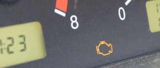
If the trouble codes have been corrected, you need to erase the Receipt from the ECU (electronic control unit) memory. Otherwise, the indicator will light up on the dashboard when there are actually no errors.
Step-by-step instruction:
- The ignition is activated, but the car engine does not start.
- The engine compartment of the car opens. Use a wrench to loosen the bolt that secures the terminal clamp to the negative terminal of the battery.
- Then you need to wait about a minute, then the battery terminal must be connected back.
- The engine compartment of the car is closed and the ignition is turned off.
- Then the power unit of the machine is started.
If the Check indicator continues to light, then you need to wait a while, it should disappear on its own. If the Check Engine light does not disappear from the dashboard, we can conclude that troubleshooting has not been performed.
User Ravil Shayakhmetov showed the procedure for independently removing the Check error from the dashboard of a VAZ car.
How can I reset errors myself?
To delete the data remaining in the memory of the control unit, a repeated self-diagnosis of all systems is performed. Once error codes are displayed, the information is recorded. Pressing the daily mileage reset button again will delete the fault data from the ECU memory.
The Glaz Szalg channel spoke in detail about resetting errors in VAZ cars.
On-board computer VAZ 2107
An on-board computer is a “smart” digital device that performs certain calculation operations by receiving data from various sensors. That is, the “on-board vehicle” is a device that collects all the necessary information about the “well-being” of the car’s systems and converts it into signs that the driver can understand.
Today, two types of on-board computers are installed on cars of all types:
What kind of ECU is on the VAZ 2107
Initially, the VAZ 2107 was not equipped with on-board devices, so drivers were deprived of the opportunity to obtain operational data on the state of the vehicle systems. However, later versions of the “Seven” with an injection engine are already conducive to installing this device.
Factory models of the VAZ 2107 (injector) were not equipped with an ECU, but had a special socket for the device and connection capabilities.
The injection model of the “seven” has a variety of different electronic components. Any driver knows that sooner or later one of these components may begin to malfunction or fail. At the same time, self-diagnosis of a breakdown in such cases is very difficult - again due to the complexity of the electronic systems of the VAZ 2107. And installing even a standard ECU model will allow you to receive data on breakdowns in a timely manner and quickly fix faults yourself.
Meaning and interpretation of error codes
Error codes in the form of one and two-digit numbers:
| Code | Description and recommendations for elimination |
| 1 | Malfunctions in the operation of the control module. The unit is subject to more thorough checking for possible problems. Problems can be both hardware and software in nature. Before performing the test, it is recommended to clean the module connector and diagnose the integrity of all wires so that the signal from the device is correct. |
| 2 | Malfunctions related to the functioning of the wiring of the fuel volume sensor in the tank. The device may produce an incorrect signal, which is often due to damaged or clogged contacts on the block. It is necessary to diagnose the sensor and also check the integrity of the wiring. |
| 4 | The control unit has detected an increase in the voltage level in the car's electrical network. The problem may be due to a low battery (when the charge decreases, the generator runs faster) or a malfunction of the generator set. You need to check the voltage regulator relay. If the battery (rechargeable battery) is discharged, it must be recharged. |
| 8 | Reduced voltage in the vehicle's electrical network. The problem is solved in a similar way - by diagnosing the generator set and battery. |
| 12 | Malfunctions associated with the operation of the diagnostic electrical circuit of the lamp on the instrument cluster |
| 13 | The microprocessor module does not allow you to determine the pulse coming from the lambda probe. The oxygen sensor is subject to diagnostics. |
| 14 | The antifreeze temperature sensor sends too high a signal to the control unit. The controller may not work correctly for the following reasons:
All elements are subject to diagnostics. |
| 15 | Malfunction related to the coolant temperature sensor (coolant temperature sensor). The controller needs to be checked because the signal from it is too high. |
| 16 | Another error indicating high voltage in the vehicle’s on-board network |
| 17 | Low voltage in machine wiring |
| 19 | The control unit reported problems with the functioning of the crankshaft position controller. The device is sending an incorrect signal. If the sensor is faulty, it may be difficult to start the engine. Sometimes the power unit does not start at all. |
| 21 | Failure associated with the functioning of the throttle position controller; there may be problems with the operation of the unit itself. If the sensor is faulty, the car engine may not operate correctly and power may be reduced. |
| 22 | A low signal is sent from the throttle position controller to the control unit |
| 23 | Incorrect pulse received by the microprocessor from the intake air temperature controller |
| 24 | The speed sensor is malfunctioning. If the controller fails, the speedometer will not function. |
| 25 | An incorrect signal is being sent from the incoming air flow temperature controller |
| 27, 28 | The control unit receives an incorrect pulse coming from the CO controller |
| 33, 34 | Error codes indicating problems with the mass air flow controller. You need to check the sensor wiring and the device itself. If the MAF (mass air flow sensor) is faulty, the engine may stall randomly and its power will be reduced. |
| 35 | The microprocessor module recorded a deviation in idle speed. You need to check the XX regulator and its connector. |
| 41 | Incorrect signal supplied by the phase regulator. It may be too low or high. |
| 42 | Malfunctions related to the electrical connection circuit of the electronic ignition system |
| 43 | The control unit has determined that the knock sensor is inoperable; an incorrect pulse transmitted from the device is possible |
| 44, 45 | Problems with the air-fuel mixture - too lean or rich |
| 49 | Vacuum Loss Diagnostic Code |
| 51, 52 | Malfunctions associated with the operation of one of the memory blocks - RAM (random access memory) or PROM (read-only memory) |
| 53 | There is no signal from the CO sensor to the microprocessor. There may be a break in the electrical circuit or failure of the controller. |
| 54 | There is no signal from the octane corrector sensor |
| 55 | The engine control unit detects a lean mixture when the load on the car engine decreases |
| 61 | Malfunctions related to the operation of the oxygen sensor. The lambda probe must be replaced. |
Self-diagnosis codes sometimes add up. For example, error 6 can be the sum of 2 and 4, and fault 9 can be the sum of 1 and 8.
Combinations of problems when performing computer diagnostics are displayed in four-digit form:
| Error code | Decryption and recommendations for elimination |
| 0030 | The microprocessor unit detected faults in the power line in the area from the oxygen controller to the neutralizer device. Wiring and regulators are subject to diagnostics. Failed devices are replaced. |
| 0036 | The power line of the second heating sensor has been reported to be damaged. |
| 0102, 0103 | The mass air flow controller is faulty; the device is sending an incorrect signal. It is necessary to check the integrity of the circuit and the regulator itself. |
| 0112, 0113 | Problems have been detected in the functioning of the intake air temperature controller. The wiring through which the device is connected, as well as the regulator itself, are checked. |
| 0115-0118 | The coolant temperature sensor is faulty. You need to look for the source of the problem in the device itself or its electrical circuit. Often the cause of the malfunction is due to liquid getting on the block to which the sensor is connected. |
| 0122, 0123 | Problems with the operation of the TPS (throttle position sensor). The throttle position controller is giving an incorrect signal. There may be interference in the electrical circuit if the line is damaged. |
| 0130, 0131 | The oxygen controller has failed. The device is subject to detailed testing and replacement if necessary. |
| 0135-0138 | The oxygen controller heating sensor is giving an incorrect pulse or is faulty. The device must be checked. |
| 0300, 0302 | Misfire detected. There can be many reasons for this problem. First of all, you need to check the operation of the spark plugs, as well as the high-voltage wires. |
| 0301 | Another error indicating misfire in the cylinders of the power unit. It is necessary to diagnose the compression level. |
| 0325 | The knock controller is reported to be malfunctioning. A possible reason is damage to the electrical circuit, then the wiring will have to be changed. |
| 0335, 0336 | Problems related to the functioning of the crankshaft position controller. The power line may also be damaged. If the wires are intact, you need to test the block on the connector or replace the sensor. |
| 0341 | Malfunction of the camshaft position sensor. The engine may not operate correctly with this problem. |
| 0346 | Malfunctions in the functioning of the phase sensor |
| 0363 | A microprocessor device detects misfires of the air-fuel mixture in the cylinders of the internal combustion engine (external combustion engine). It is necessary to diagnose the motor in detail. |
| 0422 | Failure of the neutralizing unit. The device is subject to detailed diagnostics. |
| 0443- 0445 | Malfunctions related to the operation of the adsorber sensor. The problem is that the system is not purged. Controllers are subject to testing and replacement if necessary. |
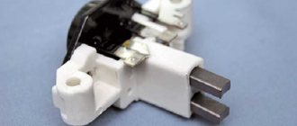
| 0480 | Malfunctions related to the operation of the power unit cooling fan. If the device does not work properly, it will cause the engine to overheat. Often the reason is oxidation of the contacts on the terminal block through which the fan is connected to the power supply. |
| 0501 – 0504 | There are reports of problems with the speed sensor. The problem may be oxidation or clogged contacts on the controller located on the gearbox. Cleaning them may solve the problem. |
| 0505 – 0507 | The microprocessor module reports problems in the functioning of the idle air control. A sensor failure will cause the idle speed to fluctuate, which can cause the power unit to trip. It is necessary to check the operation of the device and the integrity of its electrical circuit. |
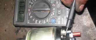
| 0511, 1514 | These fault codes are associated with damage or a short circuit in the power line of the idle speed sensor. It is necessary to test the operation of the controller and the integrity of the electrical circuit. A multimeter is used to diagnose the wiring; the damaged controller is replaced; it cannot be repaired. |
| 0560 | Incorrect signal about the voltage level in the electrical network. This value may be too high or low. The vehicle's battery and generator set are subject to diagnostics. |
| 0606 | Processor failure. You can try to delete the code from the control unit's memory. If after this the error remains, then the controller needs to be changed. |
| 0607 | Incorrect operation of the knock sensor |
| 0650 | Error code in the operation of the control power line of the control unit malfunction indicator |
| 1303 | The microprocessor unit has detected a misfire of the combustible mixture in cylinder number 3. It is recommended to quickly fix the problem, as it can lead to breakdown of the neutralizer device. |
| 2020 | Problems have been reported with the intake flap controller. The sensor is diagnosed and changed if necessary. |
| 1617 | The sensor for detecting uneven road surfaces has failed, and the power line may be damaged. |
| 1513 | A short circuit in the idle speed controller circuit is reported. The electrical circuit is subject to diagnostics, and the contact elements on the block are also checked. |
| 1578 | Incorrect operation of the throttle valve. To eliminate the problem, it is recommended to clean the device or adapt it. To complete the task, you need to turn on the ignition for forty seconds and then start the power unit. To fix the problem, you can try to tighten the terminal elements on the throttle assembly. |
| 1602 | Failures in the voltage supply were detected in the vehicle’s on-board network. |
| 1621 | The microprocessor has detected problems in the operation of the computer's RAM. It is necessary to carry out a full check of the control unit. |
| 2135 | Malfunctions related to the functioning of the throttle. If the damper is cleaned and the controller is operational, then the cause should be looked for in the control unit. The microprocessor may need to be re-flashed. |
| 2187 | The air-fuel mixture in the power unit cylinders is too lean |
The author Igor Belov spoke in detail about ways to help decipher car fault codes.
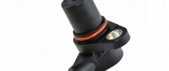
What are the errors that indicate a faulty phase sensor?
There are two error codes that indicate a faulty phase sensor:
- 0340;
- 0343.
Symptoms of problems will be as follows:
- the car moves jerkily, and the driving speed noticeably decreases;
- the power of the power unit decreases, in some cases the car cannot pick up speed above 60 km/h;
- the engine stalls when the gear is in neutral, for example, at traffic lights;
- the dynamics of the power unit decreases, shocks during acceleration, pops in the exhaust system;
- The ignition spark may completely disappear, as a result of which the car engine will not start.
Error code 0340
Error code 0340 indicates a faulty phase controller. The camshaft sensor needs to be checked for functionality. Sometimes error 0340 is associated with problems with the crankshaft position controller. The malfunction may be caused by the fact that the timing belt (gas distribution mechanism) has slipped by one tooth.
Error code 0343
Combination 0340 indicates an increased signal coming from the phase sensor. If the controller is working properly, then the contact elements on the device connector are subject to diagnostics. Perhaps the problem lies in their damage or oxidation. It is necessary to clean the contacts and ring the power line. There should always be a 12-volt voltage at the controller terminal (element A), and 0 at the other contacts.
The channel “In Sandro’s Garage” talked about troubleshooting a problem related to the operation of the camshaft sensor.
Diagnostics using special equipment
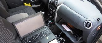
If you resort to a verification method using special equipment, you will need a computer on which diagnostic software is pre-installed.
The necessary software (programs) is downloaded from the Internet:
- "Uniscan". A series of “software” used for diagnostic testing of almost any cars from major manufacturers (USA, EU, Japan, Korea) manufactured no earlier than 2001.
- “Motor Tester”. A powerful semi-professional program with which you can diagnose many Russian-made cars (VAZ, UAZ, GAZ, etc.).
- “Vagcom” and “Vag Tool”. Two programs for diagnosing machines related to the so-called. VAG group (Volkswagen-Audi group). Allows you to work with brands such as Audi, Seat, etc.
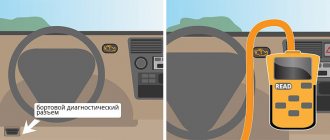
To connect to the diagnostic output, you will need a wire with an adapter. One end of the cable is connected to the header, and the other to the USB input on the computer or laptop.
For diagnostics, perform the following steps:
- A detailed inspection of the car is carried out. The car owner checks the availability of consumables. This can be brake fluid, engine and transmission oil, and antifreeze.
- The diagnostic output is searched for and a computer is connected to it. The ignition system in the car is first activated by turning the key in the lock to the appropriate position. The engine should not start. If there is a special scanner, then instead of a computer, this equipment is connected to the diagnostic connector.
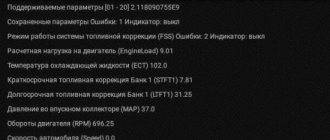
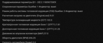
- Then the diagnostic software is launched. Depending on the developer, the utility interface may differ. In many programs, when launched, graphs or technical parameters of the car with numbers appear.
- The car begins checking for errors; to do this, press the corresponding button in the program. At the end of testing, the utility displays error codes.
How to view VAZ 2114 faults through the dashboard
You can check for errors in your car yourself, without using OBD2, as follows.
- Insert the key into the ignition.
- Hold down the odometer key and, without releasing it, turn the key to the first position.
- Release the key and look at the tidy. After this, the arrows will start running in a circle.
- Next, press the key again and quickly release it. This will allow you to install the firmware version.
- If you press the button on the dashboard again, fault codes will be displayed and they can be read.
