Any injection engine, including the 8-valve VAZ-2114, is almost completely electronically controlled and does not require adjustments during operation. Nevertheless, it becomes necessary to accurately place marks on the pulleys and flywheel in several cases - when the timing belt breaks, as well as after repairing the cylinder head. We'll deal with the causes and consequences later, but for now let's set the ignition correctly according to the marks.
Ignition systems of the 8-valve injection VAZ-2114
You can determine the type of ignition by looking under the hood:
- If you find a breaker near the “heart” of your car (analogous to a distributor installed on contact systems), then your car belongs to the first series, and the ignition of the VAZ 2114 injector on it is non-contact, based on the breaker-distributor assembly. The ignition in such systems is set by turning the distributor degree by degree, and the results of the work depend on the experience of the performer and the availability of special equipment. So, with the help of a strobe light, the system can be debugged exactly as desired by the car owner.
- If this part is not present, then your car belongs to the representatives of the tenth family, equipped with an electronic ignition system. It is impossible to set this manually, and its operation is completely controlled by the ECU. At the same time, it is not completely unadjustable, because by connecting to an on-board computer, some of its parameters can be reconfigured to your taste, but there are only a few specialists capable of doing this correctly.
IMPORTANT! The electronic system in the VAZ 2114 is designed so that the owner does not have to maintain it, so if you do not plan to participate in racing competitions with your car, it is better not to mess with the software.
Injector types
The injector controls fuel injection and can also control the ignition. On all new injection machines, the ignition is set by a computer and regulated by filling in different firmware. But this was not always the case, and on older cars, the same Japanese from the 90s, the computer regulates only fuel injection, and the ignition timing is set using a distributor and is set in the same way as on old Lada models, and depending on the speed The ignition timing is adjusted using a more complex vacuum system than on carburetor Zhigulis. Sometimes, one tube breaks, and during operating mode the traction may disappear; you will have to look for and correct this defect.
Causes of ignition problems
As mentioned earlier, in order to set the ignition in the electronic system you will have to go into the “brains”, there you can also check the functionality of the sensors, so they greatly influence the operation of the system, regardless of the type of ignition.
On the electronic type, the main causes of failures are:
- Incorrect information transmitted from sensors to the ECU. If the connection to the brain and diagnostics showed strange data coming from one or more control devices, it is necessary to use a “substitution”. The easiest way is to find a car with known good sensors, install them and double-check the results. Here you need to understand that you do not need a new one, but a working sensor, because factory defects are not excluded even on a new mechanism.
- The incoming voltage - correct from a technical point of view is 5V, but if due to a violation of the mechanical integrity of the wires or another problem with the car’s electronics, this voltage changes, the sensor readings will also change after it. If this happens, the ECU begins to adjust engine operation based on incorrect data, which leads to incorrect operation of the entire mechanism as a whole. To check this breakdown, you will need a known-good system of wires leading to the sensor or a donor car into which you can install your sensor and test the system for functionality.
- Broken ECU - if the previous two options did not give a visible result, and installing your sensor and wiring in a working machine does not change its performance, only this option remains. You can try to reflash the “brain” of the car, but due to its low cost, it is better to immediately buy a new ECU and install it on the car.
Before moving on to the radical measures proposed in the third option, it is worth additionally checking the correct location of the labels. In cars with contactless ignition, this is the ignition installation of the VAZ 2114, and for cars with an electronic system, debugging is important to check the synchronization of the injection system with the gas distribution mechanism.
High-voltage wires VAZ 2115
We install a grant thermostat on a VAZ-2114 with our own hands.
Automotive high-voltage (HV) wires play an important role for the internal combustion engine, since with their help, high current is transferred from the ignition coil to the spark plugs. The serviceability and efficiency of the wires determines the timeliness and intensity of ignition of the fuel-air mixture, and therefore the correct and uninterrupted operation of the engine. Despite their simplicity, wires have many different “sores” and can cause a lot of troubles to their owner, which in one way or another will affect his nerves and pocket.
Connection
The order of connecting high-voltage wires must be strictly sequential, since each cylinder of the engine corresponds to a specific socket on the ignition module. Considering that there is a numbering of the sockets on the ignition module body, the risk of confusing anything is minimal.
The procedure for connecting high-voltage wires of the VAZ 2114 injection type depends on the year of manufacture of your car. Fourteen cars before 2004 had 4-pin ignition modules installed, and cars after 2004 had 3-pin coils.
The connection diagram for VAZ 2114 high-voltage wires to the ignition module (until 2004) is as follows:
Connection diagram for VAZ-2114 with ignition coils (after 2004):
In the pictures you can see the numbers of the landing slots. Each number must have a corresponding cylinder connected to it (cylinder numbering is counted from left to right).
To correctly install high-voltage wires on the VAZ 2114, follow the following algorithm of actions:
— Turn off the ignition. Open the hood and remove the power terminals from the battery;
— We remove the old GDPs from the mounting sockets on the module and cylinders;
— We remember the location of the high-voltage wires of the VAZ 2114 and connect new GDPs according to the diagram. Before replacing, it would not be amiss to draw this very diagram by hand on paper so as not to confuse anything;
— We connect power to the battery and, to check whether we did everything correctly, start the engine.
When installing the wiring, do not try to connect individual air intakes to each other with plastic clamps; to do this, you must use the comb holder that comes with them. A thin clamp can easily wear through the insulating coating. Also make sure that the GDP does not bend.
Connecting armored wires on VAZ 2115 and 2113 is carried out in a similar way.
Instructions: replacing the brake master cylinder.
How to remove high-voltage wires?
Turn off the ignition. Open the hood. Pull out the wires from the ignition module and from the engine.
How to connect high voltage wires?
The BB wires must be connected in a certain order. Each wire goes to a specific cylinder and to a specific connector in the ignition module (ignition coil). There are markings both on the wires and on the ignition module. But without removing the module, the markings cannot be seen, so see the photo below.
Connection diagram for high-voltage wires:
Cylinder numbering from left to right. Ignition module numbering: first cylinder - lower left compartment of the ignition module
Second cylinder - upper left compartment
The third cylinder is the upper right,
The fourth cylinder is the lower right compartment of the ignition module.
Location
Incorrect installation and location of high-voltage wires can lead to a spark jumping from wire to wire or to ground, which, in turn, can lead to misfires and a decrease in the crankshaft speed when the car is moving at high speed.
Therefore, install the high voltage wires properly as shown in the pictures above.
Disconnect the high-voltage wires from the spark plugs and ignition coils. Clean and check the integrity of the insulation of high-voltage wires. Check the internal contact surfaces of high-voltage wires for corrosion or carbon deposits.
Use an ohmmeter to measure the resistance of the high-voltage wires.
Getting ready to adjust the ignition
In order to correctly set the ignition timing of the VAZ 2114 and carry out debugging, you need to prepare. The method described below does not require acrobatic agility from the owner and is quite feasible both in the uncomfortable and cramped environment of a garage and if the car enthusiast has a tummy.
IMPORTANT! Thorough preparation always speeds up the process of technical work significantly, regardless of what exactly needs to be repaired.
Preparation for debugging ignition marks is carried out as follows:
- The car is placed on a flat surface and placed on the handbrake.
- The second step is to remove the front right wheel, which will subsequently allow you to gain access to the gas distribution mechanism itself, which will speed up the work, make it convenient and easy, for this: a. unscrew the fastenings of our wheel and place a wheel chock under the diagonally opposite wheel (rear left); b. We lift the car with a jack, twist the wheel mounts completely and remove it.
- Finally, we need to remove the timing belt splash guard (if there is one, of course). By the way, you can not remove it entirely, but just unscrew the two lower fasteners, then it can be moved away without damaging it.
CONNECTION FEATURES
The order of connecting high-voltage wires must be strictly sequential, since each cylinder of the engine corresponds to a specific socket on the ignition module. Considering that there is a numbering of the sockets on the ignition module body, the risk of confusing anything is minimal.
The procedure for connecting high-voltage wires of the VAZ 2114 injection type depends on the year of manufacture of your car. Fourteeners before 2004 had 4-pin ignition modules installed, and cars after 2004 had 3-pin coils.
The connection diagram for VAZ 2114 high-voltage wires to the ignition module (until 2004) is as follows:
Connection diagram for VAZ-2114 with ignition coils (after 2004):
In the pictures you can see the numbers of the landing slots. Each number must have a corresponding cylinder connected to it (cylinder numbering is counted from left to right).
To correctly install high-voltage wires on the VAZ 2114, follow the following algorithm of actions:
- Turn off the ignition. Open the hood and remove the power terminals from the battery;
- We remove the old GDPs from the mounting sockets on the module and cylinders;
- We remember the location of the high-voltage wires of the VAZ 2114 and connect new GDPs according to the diagram. Before replacing, it would not be amiss to draw this very diagram by hand on paper so as not to confuse anything;
- We connect power to the battery and, to check whether we did everything correctly, start the engine.
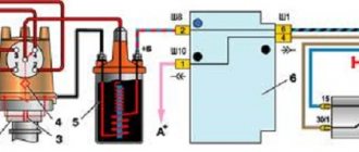
Marks and direct adjustment
When the preparation is completed and the car is ready to work with it, you can begin to set the ignition marks of the VAZ 2114. The task of the procedure is to check the synchronism of the system (correlation of the camshaft, crankshaft and injection timing), with some nuances for the electronic system.
For electronic ignition systems, there is a small nuance - the need to check the distance from the master disk to the sensor. Normally, this distance should not exceed 0.7 mm, but should not be less than 0.5 mm. You can use a valve feeler gauge to check.
The further procedure for the electronic ignition system is as follows:
- We look into the mark hatch and align the gearbox housing mark with the flywheel mark by turning the crankshaft.
- We find the mark on the oil pump pulley and make sure it matches the tide of the cylinder block.
- Align the camshaft pulley mark with the head boss.
- The work is completed, to check the correct setting, check that the gap on the disk coincides with the tide of the cylinder block, and the twentieth tooth with the crankshaft position sensor. If everything matches, you have successfully completed the task.
On a car with contactless ignition, everything is even easier; you don’t have to remove the wheels, but you will need an assistant. It is necessary to find the compression stroke of the fourth cylinder. To do this, insert a rubber cone into the spark plug hole and turn the ratchet. Pushing out the cone will mean that the compression stroke has been found.
Having illuminated the spark plug hole, we align the longest mark of the cover with the mark of the pulley. We set the breaker to the appropriate clock and check the operation of the system according to the fourth point described above.
How to set the ignition on a VAZ using marks
Almost all modifications of the VAZ-2114 and 2115 are equipped with engines with BSZ (non-contact electronic ignition). To make the setup, you need to:
- Unscrew the timing case fasteners and remove it.
Removing the timing case
- Adjust the gap from the crankshaft sensor (located near the generator pulley) to the gear disk. The permissible value is up to 0.7 mm.
Adjusting the gap from the crankshaft sensor to the gear disk
- If the distance is normal, check that the crankshaft pulley is not misaligned.
- To ensure that the marks on the flywheel align with those on the gearbox housing (can be seen on the hatch), the crankshaft must be rotated. It is convenient to do this by grasping the pulley mounting bolt.
Note! It is prohibited to turn the camshaft pulley itself.
Rotating the crankshaft pulley
- The mark on the cylinder block must align with that on the oil pump pulley. They should be adjusted.
- The last mark (on the camshaft pulley) should coincide with the other mark on the cylinder head.
Checking the marks on the camshaft and block
Having placed the marks on the VAZ model, you can see that the pistons of cylinders 1 and 4 are located at the dead center at the top, if everything is done correctly. In this case, the power unit operates correctly because the crankshaft sensor sends correct data to the ECU.
Spark based operations
You need to configure the ignition using this method as follows:
- The markings on the crankshaft pulley and timing belt are aligned. The marking on the slider guides the starting cylinder cable.
- The nut securing the switchgear housing is loosened.
- The center wire with high voltage is removed from the distributor cover.
- The cable contact is positioned near ground. This is a distance of approximately 5 mm.
- The ignition starts.
- The KRP rotates 20 degrees. The rotation occurs in a clockwise direction.
- The housing rotates in a reverse vector until a spark is formed between the contact section of the cable and the ground.
- The distributor housing is secured in this position. The fastener here is the breaker nut.
After these operations, the reliability of the OZ in traffic conditions is necessarily determined. The algorithm of actions here is as follows:
- The engine is warming up.
- The car accelerates to 40-45 km/h.
- In fourth gear, you need to press the gas pedal to the limit.
- The level of detonation is analyzed. When, after accepting the specified gear, the duration of detonation is 2-3 seconds, and the detonation stops as the car accelerates, this is normal. And when, upon reaching speed (item 2), it does not disappear, then, most likely, advanced ignition is formed. When there is no detonation when the designated gear is engaged, retarded ignition is obtained. In this situation, it is necessary to adjust the SOP until you achieve the desired result.
The better and more accurately the ignition works, the more stable the engine itself will operate.
Checking the set ignition
To check the ignition on an 8-valve engine, an injector, you should prepare:
- Multimeter.
- Set of keys and screwdrivers.
- Pliers (necessarily with insulated handles).
Attention! Due to the lack of special equipment, the described method can only test the operation of the circuits. Diagnostics of the microprocessor part will not be available.
The process is:
- When the ignition is turned off, check how tightly the high voltage wires are seated and what contact is in the module.
- Remove the connector from the module, connect a multimeter (monitoring mode should be low AC) to pins C and B, make sure there is voltage. Check the coil (2nd and 4th contacts).
Checking the presence of power on the ignition module
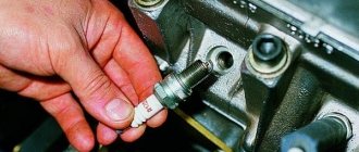
- Check the functionality of high-voltage wires. Install a working spark plug in each cap in turn, attach one end to the block and crank the engine with the starter. The presence of a spark signals that everything is normal. Its absence on each wire means the module is faulty.
Checking high voltage wires
If you managed to set the ignition correctly on the VAZ model and this was confirmed by the test, but problems are still observed, you need to check the power system.
There is one SKODA RAPID car for everyone
SKODA RAPID is a car that can safely be called unique. Why? The answer is obvious - it will suit absolutely everyone! The dynamic character of the model and precise, refined handling combined with an interesting and stylish design will not leave the younger generation indifferent.
Older drivers will appreciate the nobility of the “crystalline” design, which is partly reminiscent of the traditions of the best crystal manufactories in the Czech Republic and the cubist architecture so beloved by all residents of Prague.
Consequences of incorrectly setting timing marks
If the ignition is set incorrectly, the following negative aspects are possible:
- If the engine has 16 valves, then they become deformed or bent during operation, accumulating damage.
- The previous problem causes damage to the cylinder head.
- The guide bushings may also become unusable.
- Cracks may appear in other engine components.
Crack in the cylinder block
- The motor overheats.
- The engine piston mechanism can burn out.
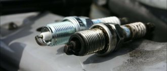
- Oil residue may appear on the spark plugs.
Oil deposits on spark plugs
- The fuel mixture loses its ignition moment.
Note! If the engine has 8 valves, then the consequences are not so critical - traction disappears, the belt quickly wears out and breaks.
After repairs, the following factors most often indicate an incorrectly set ignition:
- The car accelerates worse.
- Frequent overheating of the motor.
- The craving became much worse.
Signs of errors in the system
As already mentioned, such errors in the system can have a detrimental effect on the engine. Therefore, it is very important to detect signs of early injector ignition in time. You should pay attention to the following symptoms:
- The engine starts with difficulty.
- Fuel began to be consumed noticeably faster.
- The engine loses throttle response.
- There is a loss of power.
- At idle, the system is unstable.
- The response disappears when you press the gas.
- The engine gets very hot. There is detonation in it.
- The appearance of specific pops. They also send other components to the exhaust technology, most often to the carburetor.
Which ignition is better, early or late? Continued operation of the engine with a damaged SOP can only damage the engine even more seriously. Especially if sustained detonation occurs.