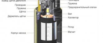
The electric motor of the heater fan (“stove”) on VAZ 2108, 2109, 21099 cars and their modifications is a commutator, DC motor with excitation from permanent magnets. Has three rotation speeds. The speed is selected by a four-position switch on the instrument panel. Below are the electrical diagrams for connecting it.
Wiring diagram for the electric motor fan (“stove”) of VAZ 2108, 2109, 21099 cars with a “low” instrument panel and mounting block 17.3722
Wiring diagram for the electric motor fan (“stove”) of VAZ 2108, 2109, 21099 cars with a “high” instrument panel and mounting block 2114
Notes and additions
— The fan electric motor can be connected to the on-board network either directly (highest speed) or through an additional resistor having two resistance spirals (0.23 Ohm and 0.82 Ohm). If both spirals are included in the chain, the speed is low, if one is 0.23, the speed is average.
More articles on electrical equipment of VAZ 2108, 2109, 21099 cars
Schematic electrical diagrams, connecting devices and pinouts of connectors
The VAZ-2109 car was produced at AvtoVAZ from 1987 to 1997. Years of production 21099: 1990-2004 - in Russia, 2004-2011 - in Ukraine. Here are colored wiring diagrams (for the injector and carburetor) with a description of all the elements for various modifications. The information is intended for self-repair of cars. Electrical circuits are divided into several blocks for ease of viewing via a computer or smartphone; there are also circuits in the form of a single picture with a description of the elements - for printing on a printer.
Like the entire car, its electrical equipment was at an average level, so owners of Nines should know the wiring diagram thoroughly for routine repairs with their own hands.
Modifications of VAZ-2109
VAZ-2109 . The basic model, which was produced from 1987 to 1997, was equipped with a 1.3-liter VAZ-2108 carburetor engine with a capacity of 64 horsepower.
VAZ-21091 . Modification of a car with a derated VAZ-21081 engine, 1.1 liter and 54 horsepower. It was mass-produced from 1987 to 1997.
VAZ-21093 . Modification of a car with a VAZ-21083 carburetor engine, 1.5 liters and 73.4 horsepower. Serially produced from 1988 to 2006.
VAZ-21093i . Modification with a VAZ-2111-80 injection engine, 1.5 liters. the first prototype appeared in 1994, mass production began in November 1998.
VAZ 21093-22 . Model made specifically for the Finnish market. It features improved interior trim, pre-installed alloy wheels and a new dashboard. The car was equipped with a 1.5 liter injection engine. Produced from 1995 to 1998.
VAZ-210934 . An all-wheel drive SUV with a VAZ-21093 body mounted on a Niva frame, on which the suspension, steering, engine, gearbox and transfer case from the same VAZ-2121 Niva model were already installed.
Wiring diagram for VAZ-2109 carburetor
- Headlight.
- Electric motor for headlight glass cleaning system. An optional part, used mainly on export vehicles.
- Limit switch for powering the engine compartment lamp.
- Klaxon.
- An electric motor drives a fan installed on the radiator of the cooling system.
- Temperature indicator that provides a control signal for the electric drive of the fan impeller.
- Alternator.
- Fluid supply valve for headlight glasses. Used in conjunction with paragraph 2.
- Fluid supply valve for the glass of the fifth door.
- Fluid supply valve to the front glass.
- Spark plugs.
- Hall sensor used to distribute ignition pulses.
- Coil.
- Limit switch for reverse gear lights.
- Fluid temperature meter in the cooling system.
- Starter.
- Accumulator battery.
- A sensor that measures the fluid level in the brake booster.
- Switch that controls the ignition system.
- Sensor for determining the position of the top dead center of the piston of the first cylinder. Installed on some export VAZ 2109 with a diagnostic system. Found only on cars before 1995.
- Diagnostic block. Optional element, installed together with item 20.
- Controller for controlling the solenoid valve installed in the carburetor.
- Starter switch contact block.
- Limit switch on the carburetor.
- Economizer valve.
- Sensor signaling an emergency decrease in oil pressure.
- Washer pump drive.
- Fan impeller motor for ventilation and heating systems.
- Resistance providing additional fan speeds.
- Speed shifter.
- Windshield wiper drive.
- Cigarette lighter.
- Illumination system for levers for adjusting heater operating parameters.
- Socket for additional equipment.
- Lamp for auxiliary lighting of the engine compartment.
- Illumination system for the glove box on the instrument panel.
- Relay and fuse link mounting block.
- Instrument panel light switch.
- Parking brake lamp limit switch.
- Brake lamp limit switch.
- Steering column switch lever block.
- Exterior lamp switch.
- Hazard switch.
- Turn on the rear fog lamp.
- Bimetallic fog lamp fuse.
- Heated glass switch on the fifth door.
- Turn signal repeaters on the front fenders.
- Central interior lighting.
- Individual lampshade.
- Switches for backlight operation on the middle pillars.
- Ignition switching unit.
- Egnition lock.
- “Low” type instrument cluster.
- Choke limit switch on the carburetor.
- Rear lights.
- Fuel level meter in the tank.
- Heated glass.
- Rear wiper drive.
- Two lamps for room illumination.
How to disassemble the VAZ 2114/15 stove
The stove on the VAZ 2114/15 is located in an extremely inconvenient place. To dismantle and disassemble it you will need:
- Phillips and slotted screwdrivers with short and long handles or a screwdriver;
- set of wrenches;
- container and rubber hose for draining coolant;
- rags, a piece of oilcloth.
Dismantling the stove radiator
Dismantling the heater radiator is carried out in the following order:
- When the engine is cold, the coolant is drained.
- The screw located behind the plastic plug is unscrewed.
- The glove compartment is dismantled. To do this, first remove the lower part, and then the cover with the lighting lamp. Then the six screws securing the upper part are unscrewed. With a slight push and turn, the top of the glove compartment lowers and pulls out.
Equipment diagram for VAZ-2109 injector
The VAZ 2109 wiring for the injector has many connectors for connecting sensors to the computer.
- TPS (throttle position sensor);
- DPKV (crankshaft position sensor);
- DT (temperature sensor);
- DSA (vehicle speed sensor);
- Canister purge valve;
- MAF (mass air flow sensor);
- DD (knock sensor) and others.
The weak point of the harnesses is the power wiring on the bottom shelf of the radiator, which is constantly exposed to high temperatures and in this place it is in no way protected from water and dirt. Another problem is a harness under the carpet next to the driver's seat. Moisture constantly accumulates there, and in order to remove it, you need to dry the floor, inevitably tugging on the rope.
Since the mid-90s, VAZ 2109 began to use engines with an injection system, which greatly changed the electrical layout of the engine compartment and instrument panel. Below is an electrical diagram of a 1999 car with an ECM type GM ISFI-2S and January 4/4.1.
- 1 - nozzle system;
- 2 - candles;
- 3 — ignition control module;
- 4 — diagnostic connector;
- 5 — General Motors or January controller;
- 6 — connector for connecting the instrument cluster;
- 7 — main relay of the system;
- 8 — fuse for power supply wiring of the controller and ignition system module;
- 9 — protection of the speed sensor and air flow meter circuits;
- 10 — fuel supply pump power protection;
- 11 — fuel pump controller;
- 12 — engine temperature meter;
- 13 — idle system;
- 14 — detonation meter;
- 15 — tank purge system for collecting fuel vapors;
- 16 — crankshaft position meter;
- 17 — speed meter;
- 18 — air flow meter;
- 19 — lambda probe;
- 20 — throttle position angle meter;
- 21 — electric fuel pump complete with fuel level sensor;
- 22 — connection of the ignition system;
- 23 — control lamp;
- 24 — ignition switch;
- 25 - switching block;
- 26 — radiator cooling fan.
Since 2002, all VAZ 2109 began to be equipped only with engines with an injection system. The diagram shows the electrical wiring harness for the Bosch MP7.0 ECM (Euro 2 standards) on a 2003 car with a VAZ 2111 engine.
- 1 — four nozzles;
- 2 — spark plugs 2109;
- 3 — ignition distribution module;
- 4 - diagnostic connector, led into the car interior;
- 5 — Bosch controller connector;
- 6 — connector for the combination of lamps and instruments;
- 7 - main switching device of the system;
- 8 — fuse-link of the main device;
- 9 — controller for controlling the parameters of the fan on the cooling radiator;
- 10 — fan controller fuse;
- 11 — fuel pump control relay;
- 12 — fuel pump wiring fuse;
- 13 — intake air flow sensor;
- 14 — throttle opening angle sensor;
- 15 — engine temperature meter;
- 16 — regulator of idle speed parameters;
- 17 — sensor for measuring detonation in cylinders;
- 18 — crankshaft position sensor;
- 19 — lambda probe;
- 20 — immobilizer control unit;
- 21 — immobilizer status indicator;
- 22 — speed sensor;
- 23 - electric motor for driving the fuel pump; in the same module there is a device for measuring the remaining fuel in the tank;
- 24 — purge valve for the gasoline vapor recovery system;
- 25 — connector of the ignition system braid;
- 26 — instrument cluster with Check Engine indicator and warning lamp;
- 27 — ignition system start relay;
- 28 - lock;
- 29 — installation and switching block;
- 30 - cooling system fan.
Relay and fuse box diagram 2109
The fuse blocks do not depend on the fuel injection system used - carburetor or injector. BP will differ only by year of manufacture of the car. That is, the mounting blocks for the carburetor and injector are the same. The VAZ 2109-099 fuse box (carburetor, injector) is located under the hood, in the compartment in front of the windshield on the left side.
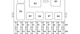
Fuse block 2114-3722010-18
K1-relay for turning on headlight cleaners; K2-relay-breaker for direction indicators and hazard warning lights; K3 - windshield wiper relay; K4-relay for monitoring the health of lamps; K5-power window relay; K6 - relay for turning on sound signals; K7-relay for turning on the electric heating of the rear window; K8-relay for high beam headlights; K9-relay for low beam headlights; F1-F16 - fuses.
Fuse block 2114-3722010-60
K1 - Headlight wiper relay, K2 - Turn signal and hazard warning relay, K3 - Windshield wiper relay, K4 - Brake light and parking light relay, K5 - Power window relay, K6 - Horn relay , K7 - Rear window heating relay, K8 - Headlight high beam relay, K9 - Headlight low beam relay, F1 - F16 - Fuses, F1 - F20 - Spare fuses.
Attention! The power terminals on the generator often become loose, heat up, spark and melt the wiring. Pay attention to this point when searching for possible faults yourself.
Electrical diagram - wiring of a VAZ 2109 car with a carburetor engine and a low instrument panel (torpedo).
A - the order of conditional numbering of plugs in the ignition switch block of VAZ 2109 electrical equipment. B - the order of conditional numbering of the plugs in the block of the electric motor of the windshield wiper of the VAZ 2109.
Picture of the VAZ 2109 electrical circuit:
Table of decoding of the VAZ 2109 electrical circuit:
Replacement process
Of course, you would not inspect all the fuses every day to detect any damage. A visual inspection is resorted to if the heater suddenly stops working. Burnt fuses are also indicated by glass washers, power windows and other devices that have stopped functioning. It will be easy for you to understand how to replace, and most importantly, identify a failed fuse, if you read our instructions.
Algorithm of actions
The manufacturer introduces a mounting block into the engine compartment of the VAZ-2108 car, in which fuses are located. This element contains fusible legs, therefore, even with a slight increase in current strength exceeding the permissible norms, these “legs” melt, breaking the contact, preventing the further movement of the “dangerous” current.
If you need to replace a failed fuse, you will not need any additional tools at all. Tweezers, which make it much easier to remove elements from the socket, are present in the mounting block itself.
So, open the hood, pay attention to the part of the space located near the windshield. This is where you will find an oblong closed box. This is the mounting block. There are two latches on its surface that ensure reliable fixation of the cover. Press these latches and the lid will immediately lift up.
Some would-be experts recommend placing a jumper on the blown fuse. Indeed, after installing such a jumper, the electrical device instantly “comes to life” and begins to delight you with its impeccable operation. Unfortunately, you are not in a hurry to rejoice at this, because during the next surge in the power supply, the fuse will not work, and therefore will allow the dangerous current to “follow” further directly to the device itself.
Sometimes drivers are confused, not understanding how to identify exactly the burnt element. There are two ways to make this determination. The first involves removing the elements one by one and visually inspecting them to determine their integrity. The second way is that in the technical documentation for your G8 you can easily find a diagram of the location of the fuses, indicating their number and current strength, as well as indicating which device “serves” this element.
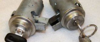
However, not only the safety element, but also the heater resistor can burn out. In this case, the heater will continue to function, but only at speed four. First, second and third speed, no matter how hard you try, will be inaccessible to you.
Removing the resistor is easy; just unscrew the screw holding it and then remove it from the heater housing. On the surface of the resistor you will easily find two spirals with different resistances; it is the resistor that allows you to control the VAZ-2108 stove. If at least one spiral burns out, the resistor stops working, and accordingly, it is impossible to regulate the intensity of the warm air supply. The resource of such a resistor is quite large; during normal operation it is enough for 125 thousand kilometers.
So, we recommend that you do not take risks and do not compete with the level of cunning with your car's electrical system. It is better to always have new fuses of different types and resistors in stock. In this case, you can replace the failed element without difficulty, spending only a little time, but continuing to move safely.
The heater and the entire heating system of the VAZ-2114 are in many ways similar to its predecessors. It is considered simple, which makes DIY repair possible.
Main components of the heating system:
- fan;
- stove tap (faucet or switch);
- radiator;
- air flow regulator.
The design is simple. Air is supplied inside the cabin through dampers. The resistor is responsible for the fan power and its operation. If the resistor on the VAZ-2114 stove fails, the regulator in the first and second positions stops working.
Important! If you do not change the element of the heating system and leave everything as is, then warming up the interior will take a very long time. In cold winter conditions, you will not have enough patience and health.
In the VAZ-2114 heating system there are two spirals, the resistance of which is 0.23 and 0.82 Ohms. When the fan is in the first position, current is supplied through two spirals. Switching to the second position allows electricity to flow through one coil, so there is less resistance.
And when the regulator is in the 3rd position, the fan receives current from the motor, that is, bypassing the resistor. So if the stove does not work in the first two positions, then the reason is in this element of the VAZ-2114 heating system.
To replace a device, you need to know where it is and why it needs to be replaced rather than repaired.
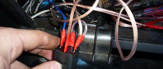
- The designers of the VAZ-2114 did not hide the resistor very far. It is located above the gas pedal. That is, you need to look for the element on the driver’s side. To access the device, you do not need to unscrew or remove anything.
- Its breakdowns are rare. Usually problems appear due to melted tip pads or burnt contacts. To fix the heating, you need to clean the contacts, buy and install a block.
- Experienced VAZ-2114 owners advise always having a new resistor in reserve. It will help you quickly, by elimination, determine the cause of the heating system problem. Not everyone can visually determine whether a resistor has burned out or not. By inserting a new one in place of the old one and checking the operation of the heater, you will see whether it is to blame or whether the problem needs to be looked for in other places.
- Principle of operation. The resistor is used to regulate the speed of the stove. It is needed to create resistance in order to reduce voltage. For the VAZ-2114 there is an element with two resistance spirals. The resistance of the first spiral is 0.23 Ohm, and the resistance of the second spiral is 0.82 Ohm. This allows you to turn on the stove in two operating modes through one resistor.