When you need to install ESP (electric windows) yourself, then, as always, on the Internet it is difficult to find correct and understandable diagrams for everyone. Having experience in radio electronics, I am laying out for everyone the correct and understandable diagrams for connecting an ESP, an intelligent glass closer Pandora DWM-210 (but it is better to install a Sheriff PWM-200), as well as simple closers only for raising the glass, installed in the wire gap on the positive side of the motor.
The process of installing the ESP is described in detail by me here: www.drive2.ru/l/4651635/
We take ESP power buttons (NOT low-current trigger (multiplex) from Itelm), namely power ones: a block from Granta, and a new model button from Kalina (it’s the power one), since they are the cutest in appearance.
These are, of course, not dual-mode imported buttons, but they will work just as well with an intelligent door closer. We also install the Sheriff PWM-200 type door closer itself. Power buttons are easy to identify by their contacts - they have thick and flat blades, while trigger buttons have thin pins like needles!
We use thick power wires (shown in bold in the diagrams) >= 1 mm2, while control wires can be used thin = 0.5 mm2. Exception! If the buttons are not on the door, but on the center console and thick wires >= 1.5 mm2 are stretched from them to each door, then you can do without a relay, since there is no duplicate button here, and each one has its own door and the drawdowns are minimal. Then you don't have to read further.
Plus +12V must be taken from the fuse block, and not from the ignition, otherwise the automatic window closer will not work when arming. It is better to take the weight from the bolt behind the mounting block, and not in the door, since the contact in the door may not be very good. Although the door contact is also good if the car is not old. Take tinned terminals.
Connection diagram for power window lifter button "AVAR"
Diagrams for connecting the backup button on the driver's door to the main button on the passenger door
When installing two buttons on one window regulator, they are usually installed in series (or in parallel, but then they must be decoupled via a relay).
The main button is the button that controls the power window of the door on which it is installed. The duplicate button is the driver's button, which additionally controls another window regulator from the driver's seat.
Daisy chain connection (for low current trigger buttons)
We connect the output of additional button 1 in the driver's door to input 6, and output 7 to input 3 of the main button on the passenger door.
We cut the wires in the block connecting contacts 5-6 and 6-3. The minus of contact 5 now goes only to the backlight, and contacts 6 and 3 now take output from additional buttons 1 and 7 of the driver's door. Attention!
Installation in parallel will cause short circuit when raising and lowering. Power wires are highlighted in bold.
Parallel connection (for our power buttons)
Since with a serial connection you still can’t do without a relay, it is better to make a button duplication circuit in parallel, decoupling the main button from the backup button through two 5-pin relays: the wires from the main button next to the driver’s ESP motor go directly to the 88th contact of the relay and from pin 30 directly to the engine, and long wires from the backup button go to pin 85 of the relay winding, and the relay feeds a powerful plus to the passenger’s ESP engine.
A parallel connection for power buttons is preferable, since there is no need for a relay on the main (passenger) button (the wires here are short), and we thereby eliminate unnecessary clicking of the relay when the main button on the passenger door operates. For non-power low-current (trigger) buttons, in this case you will definitely have to use 2 more extra relays to relieve the load on the passenger button (therefore, a serial connection is always used for trigger buttons). Further, everywhere in my circuits a parallel connection is used, since all the buttons are power
.
Connection diagram for multiplex (low-current) ESP button
ESP connection diagram when the multiplex button closes the contacts to ground
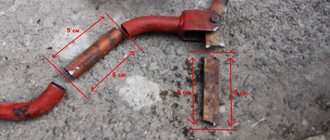
Dimensions of the installation location for the ESP “AVAR” buttons
Glass closer Pandora DWM-210
What it gives: - full glass travel in one short press (“one touch”) - BUT DOES NOT WORK ON 2 GLASSES AT THE SAME TIME (since the module has only one sensor for electromagnetic noise of the motor, current and time); — stopping the glass in any position by pressing again in any direction; — automatic stop of the glass when it encounters an obstacle in the window opening; — automatic shutdown of ESP motors when current is exceeded; — automatic closing of windows when arming the car; — automatic opening of the windows when disarming to the previous position before arming, if the parking lasted no more than 20 minutes. (The rev counter works rather conditionally and may leave the windows closed or not closed enough). The closer is installed in the driver's door.
ATTENTION! When you hold the button, the closer does not use its relays
, which take the plus (through a 20A fuse) and minus from the closer, but sends all the current directly from the button to the motor, so you need to install a relay after leaving the button with long wires!
Apparently this was done so that if the door closer fails, you can always close the window by simply holding the button. When you briefly press
the button, the door closer with its relays is activated and closes the glass.
Place the relay only at the input to the closer from the output after the duplicate button!
If this is not done, then due to subsidence along the long wires of the sequential connection of the buttons, the passenger window will barely move.
The output of the closer must be connected directly to the motor without a relay, otherwise the detection of electromagnetic noise from the motor will not work and the closer will not work!
At the output of the driver's power button, relays are not needed, since all the power wires there are short.
It is ideal to install 2 door closers on each door, as is standard on foreign cars - then the AUTO mode will be on 2 doors at once in parallel, and not alternately. In addition, you will not need to pull 2 extra thick wires to the motor from the driver's door to the passenger's door. If I had known right away that the Pandora DWM-210 is such a Ketai crap without its own relays in the power part of the closer, I would have purchased and installed a Sheriff PWM-200
, in which the power part is clearly separated from the control part and, moreover, you can close two windows at the same time in one touch! So it's definitely better!
Connecting power windows VAZ-2109
Owners of a VAZ 2109 car can replace power windows with electric windows. On 2109 cars, electric windows can be connected via standard wiring, which already has everything provided for connecting an ESP.
This circuit is used to connect ESP on more “rich” configurations of the nine and it is advisable to use it when connecting independently. Below are diagrams for connecting an ESP with fuse blocks of new and old models.
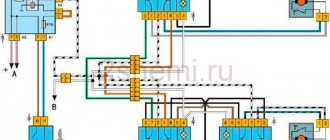
Wiring diagram for power windows on a VAZ 2109 with an old-style mounting block (17.3722):
- 1 - Mounting block
- 2 - Ignition relay
- 3 — Ignition switch
- 4 — Right door electric window motor
- 5 — Left door electric window motor
- 6 - Right door power window switch
- 7 - Left door power window switch
- K7 - Power window power relay
- A - To terminal “30” of the generator
- B - To the wiring harness block connected to the heater lever illumination display
- B - to the heater lever illumination display
- G - conventional numbering of plugs in the gear motor block
ESP diagram VAZ 2110, 2111, 2112
- 1 – mounting block
- 2 – ignition switch
- 3 – right front door power window switch
- 4 – right rear door power window switch
- 5 – electric window motor reducer of the right front door
- 6 – electric window motor reducer of the right rear door
- 7 – electric window motor reducer of the left rear door
- 8 – electric window motor reducer of the left front door
- 9 – left rear door power window switch
- 10 – left front door power window switch
- 11 – relay for turning on electric windows
- A – to power supplies
- B – to the instrument lighting switch
- C – conventional numbering of plugs in power window blocks
The power window relay for this car is located in the mounting block. On the left under the panel in the fuse box on the additional connector.
Window lifter diagram for VAZ-2115, VAZ-2115
Power windows for front doors for VAZ-2115, VAZ-2114 cars (usually power windows are installed only on front doors).
1 – mounting block; 2 – power window switch for the right front door; 3 – gear motor for the electric window of the right front door; 4 – motor reducer for the electric window lifter of the left front door; 5 – power window switch for the left front door; 6 – ignition switch; K5 – relay for turning on electric windows; A - to power supplies; B - to the external lighting switch.
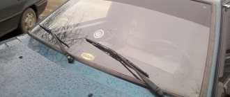
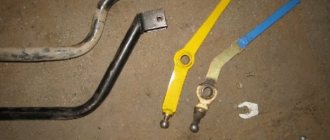
Manual window lifters
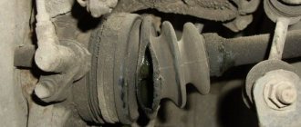
The glass lifting devices on the front and rear doors are similar. The difference is only in the sizes and proportions of the parts, while the operating principle is the same.
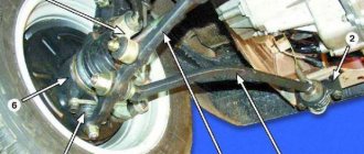
The main part is the guide in which the bracket that fixes the glass moves. The guide has fastening bolts at the top and bottom. With their help, it is installed in its position on the door. On the upper and lower edges of the guide there are rollers rigidly fixed along which the cables run that drive the glass mounting bracket.
Another part of the window regulator is the mechanism that operates the cable. It consists of a roller and a gearbox, which is rotated either by a handle or by an electric motor (if the VAZ-2114 window regulator has an electrical circuit).
To ensure that the cables are constantly lubricated and not subject to contamination, they are placed in rigid steel jackets that connect a system of three rollers together.
There are two threaded holes on the top of the glass bracket. The bolts that secure the glass holder are screwed into them.
Serial connection - diagram
We connect the output of additional button 1 in the driver's door to input 6, and output 7 to input 3 of the main button on the passenger door. We cut the wires in the block connecting contacts 5-6 and 6-3. The minus of contact 5 now goes only to the backlight, and contacts 6 and 3 now take output from additional buttons 1 and 7 of the driver's door. Installation in parallel will result in short-circuiting during lifting and lowering. Power wires are highlighted in bold.
When using trigger buttons, connect all ESP motors only through a relay. When using a conventional door closer, relays are also needed, since they are not in the long-press closer block and all the current flows through the buttons and wires from them.
Parallel connection - diagram
Wires from the main button next to the driver's ESP motor go directly to pin 88 of the relay and from pin 30 directly to the engine, and long wires from the backup button go to pin 85 of the relay winding, and the relay feeds a powerful plus to the passenger's ESP motor. A parallel connection for power buttons is preferable, since there is no need for a relay on the main (passenger) button, thereby eliminating unnecessary relay clicking when the main button on the passenger door is operating.
Scheme for any number of buttons and doors
Here you can place any number of buttons in parallel and simultaneously press them in different directions - a short circuit is impossible from the circuit design. In a situation where we press the up button on the main button, and the down button on the backup button, it will simply stop, since both power lines will have the same potential. The advantage of the circuit is that the power switching is in one place, there are no losses in the harnesses and on the buttons, there is a minimum of “pulling” of wires - 2 in total per channel + ground.
Reasons for poor performance
There are not so many reasons why the VAZ-2114 window regulator does not work well. Conventionally, they can be divided into mechanical and electrical. Let's consider the main ones:
- Glass distortion. Often the reason for poor performance is not the window lifting mechanism itself, but a violation of the position of the glass relative to its guides. This can happen either due to the bracket fastening being unscrewed, or the damp rubber fixing the glass in the holder has ceased to perform its functions. This option occurs much less frequently.
- Contamination of the guide rubbers. The glass moves inside the grooves formed by the rubber bands. These grooves tend to become clogged with dirt. It, like an abrasive, increases the friction force, which creates resistance to glass movement.
- The window lift mechanism is dirty. During operation, drivers do not realize that maintenance is also necessary inside the doors. This is especially true for the cable mechanism. Over the years, not only does contamination occur, but also the lubricant of the mechanism and cables dry out, which increases the friction force. The front left window regulator fails faster due to more frequent use.
- The next reason is wear of the plastic teeth of the mechanism drive. In this case, when you press the control button, you can hear the electric motor running, but the glass does not move.
- Broken cables. This occurs due to attempts to open frozen windows. With repeated loads exceeding the rated ones, the cables begin to delaminate and gradually fail.
Electrical reasons can be reduced to either a short circuit or loss of contact in the VAZ-2114 power window circuit.
Glass closer Pandora DWM
Connection diagram for the passenger door button in series through a duplicate button on the driver's door. Contacts 1-6 and 7-3 are always normally closed. When you press the up button, contacts 1-6 open and 1-2 close (window rises). When you press the down button, contacts 7-3 open and 7-2 closes (window down). The 30th contact of a 5-pin relay, without supplying voltage to the winding contacts, is constantly shorted to contact 88, which gives us the necessary negative contact (works like a switch). If voltage is applied to the winding, then contact 30 is disconnected from contact 88 and connected to contact 87. Contact 86 of the winding is connected to ground.
Replacing the window regulator
If the VAZ-2114 window regulator does not work, it can be replaced with a new one. To do this you need to do the following:
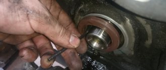
- Using a 10 mm wrench, unscrew the three nuts that hold the glass guide.
- Using a size 8 wrench, unscrew the three nuts that secure the electric motor or manual drive gearbox.
- Disconnect the glass mounting bracket from the glass holder. To do this, you need to unscrew the two 8mm bolts on the bracket.
Read also: Test drive Kia Spectra 2008 video
After this, you can pull the window regulator out of the door. The glass must remain raised. Otherwise it will be impossible to remove the mechanism.
The new lift is installed in the reverse order. However, there is no need to rush to tighten the glass mounting bracket. First you need to make sure that the glass is in the correct position in the guides and moves clearly in them.
Installation of electric windows on a VAZ
The procedure is performed in the following sequence:
- temporarily remove the glass seal located on the inside of the door;
- remove the glass, and then dismantle the window regulator fastening mechanism;
- we install devices that will operate from an electric drive;
- connect the negative terminal to the battery and check the operation of the new window regulator;
- We install the glass in place and trim the door.
Unlike conventional mechanical devices, power windows are not equipped with traditional gear reducers, but with a special drum. The shaft of a DC electric motor is inserted into its hole located in the center. In this case, the motor is only a component of the gearmotor, on which, as we found out earlier, the speed and quality of raising and lowering the windows depends.
Installation of the lifting device is quite simple. It starts with disconnecting the battery. After this, use a curved screwdriver to unscrew 3 screws, unfasten the door trim latches and remove the door pocket. Using a thin screwdriver, pry off the handle (latch) of the window lifter - the tip of the tool is inserted into the recess between the latch and the socket.
How to disassemble the door of a VAZ-2114?
To get to the window lifting mechanism, you need to remove the door trim. In addition, if you plan to replace it with an electric lift, then you need to dismantle the opening limiter, since a bundle of wires will need to be inserted into the door. To remove the casing:
- Unscrew the three screws from below that hold the plastic pocket of the trim.
- Remove the two bolts holding the inner handle. To gain access to the bolts, you need to remove the round plugs using a thin flat-head screwdriver.
- Remove the plastic trim from the door lock handle. To do this, you need to pry it up with a screwdriver and, moving it a little to the side, pull it out of its recess.
- Unscrew the lock button.
- Remove the trim. This is done as follows. A flat pry bar or a powerful screwdriver is inserted into the gap between the trim and the door frame. It should fit between the door clip and the door frame. Then you need to squeeze out the clip, not the casing. Otherwise, the clip fastening can be broken, and during subsequent installation the casing will not sit tightly in place. There are 8 clips installed around the entire perimeter of the door. They need to be pulled out one by one.
After releasing the door trim, there is no need to rush to remove it. If it is a door with an electric drive, then it is connected by a bundle of wires going to the window lift button, the pinout of which consists of seven contacts covered by a plastic connector. To disconnect it, you need to press the latch with a small screwdriver and pull out the part into which the wires go.
Types of electric windows and which ones are better for the VAZ 2109
ESPs come in various types.
- cable-type (weak and very slow, with the advantage of being cheap and being able to replace the motor separately if it suddenly burns out);
- rack and pinion (a bit weak, based on operating experience - require regular lubrication);
- articulated-lever (work quickly, make little noise, are quite powerful: they can easily cope with frozen glass).
We opt for the latter, called “Pomegranate”. Moreover, the kit of these ESPs includes everything necessary for installation - electrical wiring, buttons, plugs, all the necessary fasteners, rubber cuffs for pulling the wiring from the rack into the door.
There are also “Katran” and “Berkut”, they have a slightly different device and installation is a little more complicated, but according to reviews they are also not bad.
Installation and connection diagram for VAZ 2109 window regulators: step-by-step instructions with photos
- Before starting work, you must turn off the power supply to the vehicle's on-board network from the battery. Or we separately turn off the power circuits for the cigarette lighter and the backlight of the instrument panel and buttons, because The power supply wiring for the power windows will be connected to these circuits in the future.
- Remove the door trim. It can be removed quite easily, but it is better to stock up on mounting pins.
- First of all, we dismantle the mechanism of the standard manual window lifter, fixing the glass (for example, using office tape) in a position that provides access to the place where it is attached to the lifting mechanism.
- Unscrew the bolts securing the door glass to the standard window lifter mechanism.
- We dismantle the guide of the standard window lifter mechanism (trapezium). Unscrew the bottom nut:
- Two nuts in the middle:
- Top nut:
- The guide is free, now all that remains is to unscrew the three nuts securing our window lifter in the area of the rotation handle.
- We take out the entire door window lifter mechanism. To do this, we bring the lower pin of the guide into the hole in the door (see photo).
- By pressing with a screwdriver, we remove the upper fastening of the guide.
- Done, the window lift mechanism is disconnected. We take it out of the door cavity.
- That's it, the standard mechanism has been dismantled, let's start installing a new one. The new mechanism is attached using standard fasteners; you don’t have to drill anything new. We place the window lifter mechanism into the inner cavity of the door through the largest technological hole in an “assembled” form (otherwise it won’t fit), as if in the “open” position of the glass.
- We fasten the mechanism inside the door using two studs, which we insert into two holes that previously held the middle part of the guide of the standard VAZ 2109 window lifter. We combine them and screw on the nuts.
- The next task is to combine the mounts on the window lift linkage system with the mount on the glass. This can be done by supplying power to the power window motor contacts from an external power source, for example, any working car battery.
- When the lift mechanism is combined with the strip on the glass, we connect them using the bolts from the kit.
- It is advisable to lubricate the rubbing parts thoroughly.
- The mechanical part is complete, let's move on to the electrical part.
- We estimate the route for wiring from the door from the electric motor of the window lift drive to the installation location of the buttons - activators. The standard place for buttons in the high panel of the VAZ 2109 is two plugs to the right of the cigarette lighter, and we install them there. The hardest part is running the wiring from the door into the rack and then out of the rack under the dash. For this purpose, there are technological holes in the rack. You may need to use a special probe. The wiring is done with a wire with a cross-section of at least 1 mm. sq. We lay the wires in such a way that they do not touch any moving parts of the door or the ESP mechanism itself. We will take power for the electric windows from the cigarette lighter. Electrical connections are made according to the following diagram:
When the circuit is assembled, it is necessary to connect the battery power and check the correct operation of our system. We turn on the side lights and check the correct operation of the backlight of the ESP activator keys. If the backlight does not work, swap the sockets on the contacts of the keys, indicated in the diagram as 3 and 6. You can install the window lifters in the standard way, here are two diagrams:
Connection diagram for electric windows on a VAZ 2109 with mounting block 17.3722 (before 1998)
Connection diagram for electric windows on a VAZ 2109 with mounting block 2114-3722010-60, 2114-3722010-10 and 2114-3722010-18 (new model)
You can read more about the types of mounting blocks for front-wheel drive VAZs here.
- We check the functionality of the window regulators. The glass should move smoothly, without jamming or jerking, and should not come out of the guides. To facilitate the movement of glass in the seal, it can be treated with silicone grease.
- All that remains is to reinstall the door trim.
- That's it, the installation of the window lifters is complete, let's enjoy the completed modification!
Installation instructions
Dismantling old joint ventures from the “nine”
How to install power windows on a VAZ 2109 with your own hands, how to connect the buttons? In order for the electric SP installed in your car to last a long time and not require repairs, the connection must be carried out strictly in accordance with the instructions.
You need to install the SP as follows:
- First, you should turn off the power to the on-board network; to do this, disconnect the battery.
- Carefully remove the door trim (front or rear, depending on your purpose). This upholstery is secured with plastic clips, so it can be removed without any problems. Even if you accidentally break the piston, you can easily replace it with a new one.
- Before dismantling the window lifting device, the glass must be placed in such a way that the fastening screws can be easily accessed through the holes in the door structure. After placing the glass, you need to secure it with stationery tape. Having done this, you can unscrew the bolts that secure the glass itself.
- There is a guide nut at the bottom of the door that needs to be unscrewed. Next to the SP handle, which you can replace with a button, there are three nuts that need to be unscrewed. Next, remove the mechanism itself from the door; to do this, you need to pull it up. Installation of a new joint venture is carried out through the corresponding opening in the door, we are talking about the largest opening. It should be noted that during installation, the entire structure of the electrical joint venture must be assembled.
- To secure the structure, there are several studs on its body - they are suitable for installation in the holes in which the mounting bolts were previously located. In particular, these holes are located in the central part of the door. Once you can line up the studs with the holes, the locking nuts can be screwed in and tightened.
- Next, you need to combine the SP mount directly with the glass itself. Since the device is located in the “open” position, it is necessary to activate it and lift the seat close to the glass. The best way to do this is to temporarily connect the on-board power supply and fix the glass. When this element is brought to the metal strip, you can align the mounting holes by securing them with the screws that come with the structure. During installation, all rubbing elements of the device must be lubricated.
- The next step will be connecting to the wiring, so let's look at the wiring diagram for power windows. You need to measure the length of the wiring, which you will subsequently lay from the contacts of the electric motor of the joint venture to the place where the power buttons will be located. As for the buttons, they are usually installed on the center console, but you can install each button on a separate door. If you own a car with a high panel, then to the right of the cigarette lighter you will see special plugs designed for this.
- You will need a cable puller to run the wiring into the rack and under the center console, this can be done using a simple wire with a loop that will allow you to grab and pull the cable through. It should be noted that the cross-section of the wires themselves must be at least 1 square millimeter. As for the power supply itself, it can be supplied from the cigarette lighter or from a battery.
Sorry, there are no surveys available at this time.