Components of the fuel system
The VAZ 2114 fuel system includes:
- fuel mixture storage tank;
- gasoline pump;
- several types of filters;
- pipelines for transmitting flammable liquids;
- ramp with 4 nozzles;
- pressure regulator;
- cap on the tank neck.
The steel fuel tank serves as an object for storing fuel; it contains a high-pressure pump and a fuel availability indicator controller, which transmits a signal to the control panel. The pump has a coarse filter that prevents large particles of debris, rust and various impurities from entering the fuel system.
There is a fine filter near the tank; this unit guarantees thorough cleaning of the flammable liquid from the main line to the nozzles.
The injectors are placed on the fuel rail, which securely fastens them to the engine. Fuel injection is carried out using the system control unit. The pressure regulator controls the level of fluid injection between the inlet hose and the ramp line. The excess combustible mixture is returned back through the nozzles, along a separate tank drain line.
The temperature of the fluid that performs the reverse stroke increases by 6-14 degrees, this happens because the fuel circulates under the base of the machine and the blazing engine, and also rubs against the walls of the hose.
This circulation of the combustible mixture increases the temperature of the total liquid in the tank. Fuel vapors appear, which, according to a certain pattern, enter the fuel container and do not escape into the atmosphere; the fuel injection system ensures the safe capture of evaporation, destroying the vapors during engine operation.
Before carrying out repairs or preventative actions on the power system, it is important to reduce the pressure inside the unit. To prevent fuel spillage when removing the wires, it is important to secure the ends of the hose with microfiber.
The vehicles are equipped with a VAZ 2114 fuel supply system, which effectively supplies fuel at various inclinations of the vehicle, as well as when the liquid level in the tank is low.
Principle of operation
Fuel system VAZ 2114
It is made of steel, consists of two firmly welded parts, the neck through which the fuel enters is connected to the tank with a rubber pipe and secured with clamps.
Gasoline pump VAZ 2114
This tool with an electric mechanism is located in a tank with a fuel mixture level indicator. Its actions are coordinated by the engine control box, through a special pump relay, which supplies fuel through the line to the injectors. At idle or when the engine is completely turned off, the pressure is maintained due to the action of a one-way lock, which is located near the unit itself.
The VAZ 2114 power system has a fuel pressure regulator and injectors. The voltage is supplied to them from the battery through the main relay. Thus, the amount of driving fluid is indicated by the duration of the pulses, which are generated by the engine control unit and transmitted to the injectors.
Ramp
Located on the intake manifold, it includes a fuel control element and a pressure valve with a spring-loaded diaphragm. It, in turn, divides the regulator body into 2 parts: the fuel part regulates the pressure of the combustible mixture, the air part, due to the rarefaction of the air, raises the membrane and produces constant fuel pressure readings in the rail.
When the engine starts, the vacuum behind the damper decreases, the diaphragm closes the power system valve, so the pressure increases. When the vacuum is maximum, then the fuel pressure decreases. The regulator is not dismountable, so if it fails, it is replaced with another one.
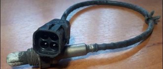
Lean sensor
The pump module has a float, which is located in the tank cavity. When the position of the float changes, the resistance of the unit changes proportionally. According to a certain signal, the fuel quantity indicator on the dashboard displays the presence of fuel in the system.
Why does the sensor often fail?
Due to:
- fragility of the case;
- frequent temperature changes;
- condensation formation in the tank;
- when using a low-quality combustible mixture;
- oxidation of contacts when sealing is broken.
That is why it is so important to carry out preventive maintenance on time, clean the unit, change contacts in order to prevent its destruction. Changing a device is not that easy. Many markings are original and unique, which means that the services of professionals will be required, which are also not cheap.
Hoses and pipelines
Such irreplaceable products guarantee uninterrupted circulation of flammable liquid from the container to the main line and nozzles, and if there is excess, they transfer the residual liquid back to the tank. The pipelines are located on the bottom of the vehicle, they need to be carefully checked, cleaned, inspected for integrity, various deformations identified and promptly eliminated in order to avoid fuel leakage, as well as poor transmission to the injectors.
Another function of the pipelines is the transfer of fuel vapor from the tank to the activated carbon section, where waste is collected when the engine is turned off. After it is started, the electromagnetic device is triggered and the vapors escape into the engine, where they are destroyed.
Highway
The design of the VAZ 2114 fuel system includes a main line that guarantees the supply of fuel to all injectors. Today, the fuel pressure regulator is placed in the tank and is not located on the line; there is also a service valve, which performs the function of eliminating air after a technical inspection of the vehicle.
The fuel injection system of the VAZ 2114 includes an uninterrupted mode for collecting fuel vapors, and the gravitational unit located in the device helps prevent fuel from leaking when the vehicle is in an emergency position.
When the engine's air consumption is high, the system is purged more intensively. The filter element is made of durable paper material, after which the air moves through the mass air flow sensor and moves into the intake hose, which leads to the throttle assembly. Thus, the operation of the fuel fluid supply mode of an engine with a fuel injection system on a VAZ 2114 car occurs.
Spare parts catalog VAZ-2114
- Body Body 60 Body
- Body panels 21
- Body panels 20
- Body panels 19
- Body floor 14
- Windows 11
- Front frame 4
- Side and rear frame 4
- Trunk lid 18
- Front doors 15
- Rear doors 9
- Tailgate 28
- Front seats 14
- Ventilation and heating system 23
- Interior accessories 14
- Hood 28
- Engine 532 Engine 1
- Fuel tank 41
- Silencers 30
- Radiator 29
- Electronic blocks 19
- Clutch 29 Clutch 10
- Gearbox 27
- Front wheel drive 42
- Differential 24
- Frame, bumpers and engine mudguards 76 Front bumper 14
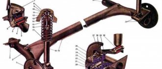
- Front axle Steering knuckles and hubs 24
- Steering control 99 Steering column 19
- Electrical equipment 1867 Generator (11, 13, 15) 15
- Instruments and lighting 110
- Tools and accessories 5 Driver's tools 5
- Standard parts 287 Studs, bolts, screws 103
- Oil seals 30
- Rolling bearings layout 72
- Plug installation diagram 5
ceda62ec37c107cab448f9fa6c585944
Do-it-yourself cleaning of injectors on a VAZ-2114
An important element in the entire engine system are injectors. They are responsible for fuel injection, which means the operation of the entire engine depends on their lifespan.
Injectors can become unusable due to many factors. The VAZ 2114 injectors themselves last approximately 100-120 thousand kilometers.
However, this is provided that gasoline complies with European standards, but in Russia the standards are often not met, which is why the injectors fail after 60-80 thousand kilometers, or even earlier.
Failure of injectors can adversely affect many vehicle systems. However, the life of the injectors can be increased if they are cleaned in a timely manner.
Why do you need to clean injectors:
- to extend the life of injectors;
- Dirty injectors increase fuel consumption and reduce the vehicle's dynamic performance.
In other words, cleaning the injectors will help the car drive smoother.
Injector malfunctions
You can understand that the nozzle requires cleaning by the following signs:
- unstable engine operation;
- unexpected sharp increase in fuel consumption;
- misfires at idle;
- reducing the acceleration speed of a car when the pedal is fully pressed to the floor.
Remember that with these signs the nozzle may no longer be working, so you need to check its functionality before cleaning. This is checked this way: with the engine running but cold, you just need to touch the injectors - they should pulsate.
There is also another way - the car is added to idle speed, after which the cap nuts on the injectors are loosened - the result of this should be a decrease in speed, if this does not happen, then the injector needs to be cleaned.
However, it is much wiser to clean the injectors ahead of time before problems arise. Timely prevention is much more profitable than cleaning when problems arise. Therefore, let's talk about the process of replacing injectors.
Replacing injectors
Of course, a car service center can replace the injectors for you. The price for this service starts from 1500 rubles. However, to save time and money, it makes sense to change the injectors yourself.
Removing injectors yourself
Here is a simple algorithm for removing injectors that all car owners can perform.
1.Disconnect the negative terminal from the battery
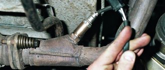
2.Take two 17mm wrenches and relieve the fuel pressure by unscrewing the fuel pipe fittings.
3. Separate the electrical connector from the fuel rail.
4.Take a Phillips screwdriver, unscrew the screw on the bracket on which the fuel pipes are attached, and remove it.
5.Use a 5mm hexagon to unscrew the two screws on the fuel rail mounting
6. Move the ramp in the direction of the injector axis, remove all 4 injectors from the engine and remove the ramp towards the left side of the vase.
7.Press the spring clip (1) located on the injectors, move it aside, and disconnect the electrical connector (2)
8.Using a screwdriver, move the injector clamp along the ramp and remove it (on new ramps, the bracket is simply removed).
9.Remove the nozzle from the hole on the ramp, slightly rocking it from side to side.
10.Remove the O-rings that are located on the nozzle body and sprayer using a thin screwdriver
That's all, now the injectors are ready for cleaning.
Do-it-yourself injector cleaning
For cleaning you will need electrical tape (wire) to secure the joints, a carburetor cleaner in a can, a syringe and a thin tube. The cleaning algorithm is as follows.
1. Insert the tube into the cap (nozzle) of the can 2. Insert the end of the tube into the hole of the syringe (without a needle) 3. Attach the end of the syringe to the nozzle 4. Start injecting the product through the tube, simulating fuel injection.
You need to inject until the coming out stream becomes smooth and clean. Then this will mean that the injector is clean.
Another way, if you have a battery nearby, you can try applying voltage to the injector with ordinary wires (polarity does not matter) simulating their operation and at the same time spraying liquid to clean the carburetor.
After this, you need to put on new O-rings and you can begin assembly, having first checked the resistance, which should be in the range of 11-15 Ohms. Reassemble the injectors in the reverse order of disassembly.
You now have a clean injector. Its service life, which means the normal operation of the engine, is increased.
How to remove the fuel rail of VAZ 2114, 2115 injectors - step-by-step instructions
1. First, you need to relieve the pressure in the fuel system; to do this, you need to turn off the fuel pump. To quickly turn off the fuel pump, simply remove the fuse that is responsible for this device from the socket in the fuse block. Next, you need to start the engine and let it run until it stalls. If you don’t want to go to the fuses, then you can try to turn off the power to the fuel pump in another way, for example, by disconnecting the fuel pump power supply.
2. Next, turn off the ignition.
3. Disconnect the negative terminal of the battery.
4. Disconnect the air receiver hose, as well as the vacuum hose from the pressure regulator.
5. Using a wrench set to “17” (some have a wrench set to “22”), unscrew the fittings and move the tubes to the side.
6. Then disconnect the fuel rail power wires.
7. Next, remove the clamping bar securing the fuel pipes.
8. Take the hexagon at “5” and use it to unscrew the two bolts securing the fuel rail.
9. Remove the injectors from their sockets, while slightly pulling the ramp along the axis.
10. Now you can remove the fuel rail from the car. Be extremely careful and careful not to damage the contacts of the injector connectors and sprayers. Make sure that nothing, such as dirt or dust, gets into the channels or fuel lines.
11. When unscrewing the union nut, hold the fitting using a second wrench.
12. Cleaning the ramp from dirt should be done exclusively with a special liquid for cleaning fuel cells (ABRO, WD-40).
This completes the removal procedure, all that remains is to carry out repair work, replace faulty parts and reassemble everything in reverse order. Thank you for your attention, see you again at VAZ Repair!
The principle of operation of the main elements of the fuel unit
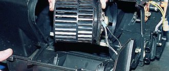
Video Replacing the cabin air filter on a VAZ 2114 VAZ 2115 VAZ 2113 Lada Samara 2
Fuel system VAZ 2114
Container for storing flammable materials
It is made of steel, consists of two firmly welded parts, the neck through which the fuel enters is connected to the tank with a rubber pipe and secured with clamps.
Gasoline pump
This tool with an electric mechanism is located in a tank with a fuel mixture level indicator. Its actions are coordinated by the engine control box, through a special pump relay, which supplies fuel through the line to the injectors. At idle or when the engine is completely turned off, the pressure is maintained due to the action of a one-way lock, which is located near the unit itself.
The VAZ 2114 power system has a fuel pressure regulator and injectors. The voltage is supplied to them from the battery through the main relay. Thus, the amount of driving fluid is indicated by the duration of the pulses, which are generated by the engine control unit and transmitted to the injectors.
Ramp
Located on the intake manifold, it includes a fuel control element and a pressure valve with a spring-loaded diaphragm. It, in turn, divides the regulator body into 2 parts: the fuel part regulates the pressure of the combustible mixture, the air part, due to the rarefaction of the air, raises the membrane and produces constant fuel pressure readings in the rail.
When the engine starts, the vacuum behind the damper decreases, the diaphragm closes the power system valve, so the pressure increases. When the vacuum is maximum, then the fuel pressure decreases. The regulator is not dismountable, so if it fails, it is replaced with another one.
Fuel mixture control sensor
The pump module has a float, which is located in the tank cavity. When the position of the float changes, the resistance of the unit changes proportionally. According to a certain signal, the fuel quantity indicator on the dashboard displays the presence of fuel in the system.
Why does the sensor often fail?
- fragility of the case;
- frequent temperature changes;
- condensation formation in the tank;
- when using a low-quality combustible mixture;
- oxidation of contacts when sealing is broken.
That is why it is so important to carry out preventive maintenance on time, clean the unit, change contacts in order to prevent its destruction. Changing a device is not so easy
Many markings are original and unique, which means that the services of professionals will be required, which are also not cheap.
Hoses and pipelines
Such irreplaceable products guarantee uninterrupted circulation of flammable liquid from the container to the main line and nozzles, and if there is excess, they transfer the residual liquid back to the tank. The pipelines are located on the bottom of the vehicle, they need to be carefully checked, cleaned, inspected for integrity, various deformations identified and promptly eliminated in order to avoid fuel leakage, as well as poor transmission to the injectors.
Another function of the pipelines is the transfer of fuel vapor from the tank to the activated carbon section, where waste is collected when the engine is turned off. After it is started, the electromagnetic device is triggered and the vapors escape into the engine, where they are destroyed.
Highway
The design of the VAZ 2114 fuel system includes a main line that guarantees the supply of fuel to all injectors. Today, the fuel pressure regulator is placed in the tank and is not located on the line; there is also a service valve, which performs the function of eliminating air after a technical inspection of the vehicle.
The fuel injection system of the VAZ 2114 includes an uninterrupted mode for collecting fuel vapors, and the gravitational unit located in the device helps prevent fuel from leaking when the vehicle is in an emergency position.
When the engine's air consumption is high, the system is purged more intensively. The filter element is made of durable paper material, after which the air moves through the mass air flow sensor and moves into the intake hose, which leads to the throttle assembly.
Thus, the operation of the fuel fluid supply mode of an engine with a fuel injection system on a VAZ 2114 car occurs.
Why do you need a fuel pressure regulator?
As mentioned above, this regulator maintains the required fuel pressure necessary for normal operation of the injectors, taking into account one or another operating mode of the power unit. In other words, the RTD affects the amount and intensity of the fuel supply that enters the engine cylinders through the injectors.
Simply put, the amount of fuel supplied to the engine at the time of injection depends on the pressure that is created inside the fuel rail (rail), as well as on the pulse duration for opening the injector and the vacuum in the intake manifold.
For more accurate dosing and maintaining constant pressure, a diaphragm valve-regulator is used, which experiences fuel pressure on one side, and a spring force on the other. RTD is used in power systems where there is a so-called “return”. The regulator is installed at the fuel rail. Also, this element can be located in the fuel tank, while such systems do not have a return line.
- Let's first look at the common design in which the regulator is located in the fuel rail. The element operates on the following principle: the fuel pump forces fuel from the fuel tank along the line. The resulting fuel pressure acts on the regulator. The device itself has two chambers (a spring chamber and a fuel chamber), which are separated by a membrane. On one side, the membrane is pressed by fuel, which enters the regulator through special inlet holes, and on the other side, there is spring pressure and intake manifold pressure. If the fuel pressure turns out to be stronger than the spring force and the pressure in the inlet, then the regulator opens slightly, resulting in some of the fuel being discharged into the return line. The fuel returns through the return line to the fuel tank.
- In systems without a return line, the regulator is usually located directly in the tank. The advantages include the absence of an additional pipeline. The injectors are supplied with the required amount of fuel directly from the tank, that is, excess fuel does not enter the engine compartment, and there is no need to deliver it back to the tank. This also allows us to talk about less heating of the fuel and provides a number of additional advantages in the form of less intense evaporation.
The fuel pump supplies the injectors with a strictly defined amount of fuel in relation to specific conditions and operating modes of the internal combustion engine. Let us add that in this system there is additionally an excess pressure relief valve, which helps to avoid its increase to a critical level.
Methods for cleaning injectors
Injector flushing additives
Additives that are poured into the tank
There are a huge number of different additives for flushing the injector. Such additives are poured into the car tank and mixed with fuel. The mixture of fuel and additives enters the main elements of the fuel system and flushes them, including the injectors. But, as a rule, such washings do not bring much results, since all the dirt that was washed away to the injectors gets and settles on them, which can only aggravate the situation. Using this method is not recommended.
Ultrasonic cleaning
Ultrasonic cleaning of injectors
This washing is considered as effective as washing the injectors during dismantling. We will not dwell on this method, since this method of washing can only be carried out at a service station. And the price of this method is not small, from 2000 rubles to 5000 rubles.
Clean in place without removal
This flushing method is carried out using special additives, but differs from the first method in that this flushing is used only on the injectors without going all the way along the fuel line. We will dwell on this method in more detail.
Washing with dismantling
This method is very reliable and probably the most popular among garage car enthusiasts who like to repair their car themselves. After reading this article, you can easily wash the injectors on a Lada car with your own hands without any special knowledge.
Replacing the fuel pump VAZ 2114
You can turn to specialists, although replacing the fuel pump on a VAZ 2114 is often done by yourself.
You don't need any special skills or specialized tools. You will need this set:
- Key to 17;
- Ratchet with heads 10 and 7;
- Crosshead screwdriver.
Next follow the instructions:
- Remove the rear seats by removing two plugs and bolts with a 10mm ratchet. Behind them you will see a sound insulation slot made in the shape of a U. Under it is the pump cover.
- Use a screwdriver to unscrew the cover, after which you will see the upper part of the module.
- Disconnect the wiring harness that goes to the module.
- Relieve pressure in the system. To do this, start the engine until all the fuel is used up in the line. In other words, wait for the car to stall.
- Disconnect the battery.
- Using a wrench, unscrew the tubes on the gas line.
- There are 8 nuts around the perimeter of the clamping ring, which also need to be removed. Here you will need a 7 ratchet.
- Remove the pressure ring.
- After the manipulations have been completed, the module can be removed, a new one can be installed in its place, and the system can be reassembled in the reverse order.
Having removed the module, you can also replace the failed pump, thereby saving money on purchasing the entire module. But to do this kind of work, the module will have to be disassembled.
Fuel pump separately
It is recommended to look for the module itself; it is almost always available in specialized auto parts stores!
This procedure is performed as follows:
- The wiring block is disconnected from the cover and the fuel pump, after which the fuel level sensor is removed. Here you just need to press out the two latches, after which the sensor will begin to move along the grooves towards the cover.
- Disconnect the drain pipe from the housing by prying it off with a screwdriver.
- The coarse filter is pryed off and removed, and the lock washer is removed.
- Press the plastic latch with a screwdriver, which will allow you to push the pump out of the holder with your finger.
- Also remove the corrugated tube located on the pump nozzle. Try heating it with steam, which will make the removal process easier.
- Reinstall the new fuel pump and perform the assembly procedure in reverse order.
After replacing the electric fuel pump, reinstall the fuel module. Remember, the arrow on the module must face towards the luggage compartment of the car.
Don't forget to perform one more important procedure. It involves replacing the battery and starting the engine for a while. This will allow you to determine if there are any leaks in the connections. If they are missing, it means you did all the work absolutely correctly.
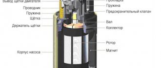
Operating principle and typical failures
A fuel pump is a kind of small electric motor that pumps fuel and creates pressure in the fuel rail of a VAZ 2114 car. The pump is a component of the fuel module.
Structurally, the pump and electric motor are a single unit. Its electrical part is washed with fuel, which provides cooling, plus lubricates the surfaces that come into contact with each other.
Fuel pump VAZ 2114
There are many signs of breakdowns, which indicate a failure or malfunction in the fuel system, or more precisely the fuel pump. Almost every person is able to detect some of them:
- The engine does not start;
- When you try to start the engine, you cannot hear the electric motor;
- The engine runs intermittently;
- Jerking occurs when moving at low speed.
Causes
As for the reasons why the fuel pump fails, they may be:
- Fuse on the pump is broken;
- Failed relay;
- Failure of the pump electric drive;
- Poorly secured block masses;
- Damage to the pump itself;
- Missing or poor contacts at the motor terminals.
In fact, it is extremely rare for an electric motor to break down. This is due to the active cooling of the element by fuel, which not only cools, but also flushes all its components.
Shidron blower and mesh
But the centrifugal gate hydraulic supercharger suffers more often than others. The reason is small contaminants in the fuel, which end up inside the mechanism, rub against the structure and wear them out. The performance of the unit drops, the pressure decreases. This leads to the formation of the first signs of pump wear, operation noise increases, and the engine refuses to start. It is impractical to repair a broken pump; it must be completely replaced.
How to clean injectors on a VAZ 2114
Hello dear readers! In today’s article I want to talk about how to clean the injectors on a VAZ 2114 yourself. First, a little theory.
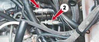
VAZ 2114 engine power supply system.
In the photo pos. Figure 2 shows a VAZ 2114 fuel rail on which four injectors are installed, position 1, which actually need to be cleaned.
When should injectors be cleaned?
It is recommended to clean the injectors if:
- the engine is unstable,
- fuel consumption has increased,
- there are misfires at idle,
- The car's dynamics have deteriorated.
How to remove injectors on a VAZ 2114?
On different cars, injectors are removed in different ways, however, as a rule, the principle is the same.
- First of all, disconnect the battery.
- Next, unscrew the two 5mm hex screws.
- Using the fitting plug (located on the left of the ramp, pos. 3), release the pressure.
- Each injector is secured to the fuel rail with a latch. Remove all injectors.
And so the injectors are dismantled, now you need to check them.
Injector diagnostics.
To diagnose the performance of the injectors, you will need a multimeter, which must be turned on in resistance measurement mode up to 200 Ohms. Insert probes between the contacts and take readings.
The resistance of a working injector should be somewhere from 11 to 15 ohms. If your injector is broken, or the resistance is much higher, then I advise you to replace it.
Do-it-yourself cleaning of VAZ 2114 injectors: instructions.
After checking the injectors, start cleaning. To do this, you need to assemble the following circuit. Two contacts are output from the battery in series through the lamp, then through a switch (microphone or non-latching button). These two contacts connect directly to the injector.
The question arises of how to connect to the nozzle; you need to know the polarity of the nozzle itself. On some injectors, the polarity is indicated on the body with a plus sign, on some, the polarity is not indicated. In such cases, it is necessary to install the fuel rail as shown in the photo.
Then the left terminal from you will be a plus, and the right one will be a minus.
How to clean injectors?
For cleaning, use ABRO CARB & CHOKE CLEANER cleaning solution (carburetor cleaner).
Many sites describe cleaning methods using all kinds of adapters, hoses, etc., everything is much simpler.
- Remove the top of the carburetor cleaner can.
- Insert the valve-spray system of the can into the nozzle.
- Connect the two contacts of our circuit to the injector contacts. Press down on the nozzle installed on the can. For one or two seconds, use the switch to activate the circuit so that the nozzle starts working (it is not recommended to hold it for more than two seconds at a time).
Important : Be sure to follow safety precautions. Spray strictly away from yourself, take care of your eyes, use protection!
For more information on cleaning injectors, watch the video.
We remove the fuel rail on a 16 valve VAZ-2112 with our own hands
Dismantling the fuel rail on a 16-valve VAZ-2112 is carried out for different purposes. This is mainly due to associated repair and diagnostic operations. The process is not complicated enough and is completely doable with your own hands.
The video material will tell you how to remove the fuel rail, the entire procedure and the nuances of replacement.