How does the intake manifold length change system work?
An intake manifold with a variable length system is used in both gasoline and diesel engines to ensure better filling of the combustion chamber with air at different engine speeds.
At low speeds, maximum torque is required to be achieved as quickly as possible, which is achieved by using a long intake manifold. High revs bring the engine to maximum power with a short intake manifold.
This system works the same on most cars. An axis with flaps is installed in the intake manifold, which block or open the path to air flow along one of two paths - short or long.
The system for changing the length of the intake manifold usually consists of the following elements:
- receiver with check valve
- solenoid valve
- mechanism for changing length (pneumatic chamber)
- axle with flaps
- connecting vacuum tubes
- wiring to the solenoid valve
Let's look at the design and operation of the system in more detail using the example of a Chevrolet Lacetti.
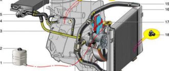
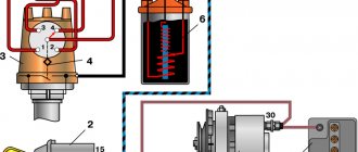
In the photo below I noted:
- red arrow – receiver with check valve
- green arrow – solenoid valve
- blue arrow – wiring to the solenoid valve
- yellow arrow – mechanism (pneumatic chamber) for changing length
- numbers - connecting vacuum tubes: 1 - from the solenoid valve to the mechanism (pneumatic chamber), 2 - from the manifold to the receiver, 3 - from the receiver to the valve.
With the engine turned off, the rod of the mechanism (pneumatic chamber) is fully extended and the system is in the state of a short manifold. As soon as we start the engine, a vacuum is created in the manifold and the pressure drops to 30-33 kPa. Voltage is applied to the valve and it opens, thereby releasing vacuum from the manifold through the receiver into the working mechanism (pneumatic chamber). The pneumatic chamber retracts its rod and, turning the valve axis, transfers the system to a long manifold, which ensures throttle response at low engine speeds. The system will remain in this position until the engine reaches a speed of 4.5 thousand rpm. After this, the ECU turns off the voltage supply to the valve and it closes, cutting off the vacuum supply to the pneumatic chamber. The pneumatic chamber rod should now fully extend and rotate the damper axis again into short manifold mode. But how will it come out if the pneumatic chamber is sealed and it needs air access so that the spring in the pneumatic chamber can move the rod? It's like putting a bottle in water upside down. Water will not get into it until you make a hole in the bottom to let the air out.
For these purposes, the solenoid valve also has a third fitting, which is closed by a cap (filter), which is located at the bottom and the green arrow points to it. This is an atmospheric fitting. When the voltage is turned off, the solenoid valve not only blocks the vacuum from the receiver to the pneumatic chamber, but also opens the transition from the pneumatic chamber to the atmospheric fitting, allowing the pneumatic chamber to draw in air and extend the rod.
Now let's briefly look at the device and check each node separately.
Turbulence in the intake manifold
This paragraph does not apply to engines with direct injection. The fuel enters the intake manifold in a finely atomized form and is then mixed with air. Some of it may settle on the walls of the intake manifold under the influence of electrostatic forces. This phenomenon is extremely undesirable, since as a result, much less fuel will enter the cylinders, and the air-fuel proportion calculated by the electronic control unit will be violated in the direction of increasing the volume fraction of air.
Turbulence helps combat fuel condensation. Under its influence, the fuel is better atomized, and its combustion occurs more completely. As a result, engine power increases and the risk of detonation decreases. To ensure the appearance of turbulence, the inner surface of the intake manifold is not polished, but rather made rough. Here it is important to achieve the optimal value of turbulence, since as it increases, pressure drops begin to occur inside the intake manifold, and engine power decreases.
Intake manifold length control solenoid valve
The valve consists of a body, a locking mechanism, three fittings and an electromagnetic coil. To remove the valve from the car, just bend the latch on the receiver side and slide the valve down
The valve has three fittings. One of them (atmospheric) is closed with a lid. It must be removed to check and remove dirt.
To check the valve's closing properties, simply blow into the side fitting. In this case, the air should go out into the lower (atmospheric) fitting, but not into the upper one. If you apply voltage to the valve, then everything should be the other way around.
To check the valve winding, just press the clamp of the wire block and remove it
There will be two contacts visible on the valve. You need to connect an ohmmeter to them and measure the resistance, which should be several ohms. If the resistance is normal and the valve does not work, then you need to check the incoming voltage at the block, which should be about 12 V. Don't forget to start the engine to measure the voltage.
Receiver (vacuum tank) of the system for changing the length of the intake manifold
This is a cylindrical container with a check valve inside. The check is very simple and consists of two points:
- check integrity to ensure there is no vacuum leak
- disconnect the tube going to the solenoid valve, and disconnect the second tube from the manifold (tube No. 2). Blow into this tube - no air should pass through. But when sucked into itself, the air must pass through!
Shape and volumetric efficiency
One of the most important parameters of the intake manifold that determines its efficiency is its shape. The basic rule that all engineers adhere to is that the intake manifold should not have any angular shapes , as this will provoke pressure drops and, as a result, worse filling of the cylinders with air or working mixture. Therefore, all collectors have smooth transitions between segments and rounded shapes.
The vast majority of current collectors use runners. They are separate pipes diverging from the central entrance of the manifold to all available intake channels in the cylinder head. Their task is to use a phenomenon called Helmholtz resonance. The operating principle of the design is as follows.
At the moment when suction occurs, air flows at a very high speed through the open inlet valve. When the valve closes, the air that did not have time to enter the cylinder retains a large impulse, which means it presses on the valve, resulting in a high-pressure zone. Then pressure equalization occurs, with lower pressure in the manifold. Due to the influence of inertial forces, leveling occurs with fluctuations: first, air enters the runner at a pressure lower than in the manifold, then at a higher one. This process occurs at the speed of sound, and before the intake valve opens again, oscillations can occur many times.
Article on the topic: Getting rid of knocking in hydraulic compensators using oil additives
The smaller the diameter of the runner, the greater the change in pressure due to resonant air vibrations. As the piston moves down, the pressure at the outlet of the runner decreases. This low pressure pulse then travels to the manifold inlet where it turns into a high pressure pulse that travels in the opposite direction through the runner and valve, after which the valve closes.
To achieve the maximum effect from resonance, the intake valve must open at a strictly defined moment, otherwise the result will be the opposite. This is quite difficult to achieve. The gas distribution mechanism is a dynamic unit, and its operating mode is directly dependent on the crankshaft speed. The pulses are synchronized statically, the synchronization depends on the length of the runners. The problem is partially solved by selecting the length for a certain speed range at which the greatest torque is achieved. Another option is the use of systems for changing the geometry of the intake manifold and electronic timing control.
Working mechanism (pneumatic chamber) of the system for changing the length of the intake manifold
This is the weakest link in this chain.
The pneumatic chamber consists of a body (metal or plastic), a rod, a diaphragm and a spring.
Most often, the system for changing the geometry of the intake manifold fails precisely because of a worn-out pneumatic chamber diaphragm. It can be called a consumable item.
To check the integrity of the spring and diaphragm, simply disconnect the vacuum tube and press in the rod. The rod should enter without jamming, and when released, it should move out sharply. This means the spring is intact and the damper axis does not jam.
Now press the rod in and close the fitting with your finger. The rod should not come out of the pneumatic chamber completely. If it comes out, it means the diaphragm is torn.
Here is a video of the working mechanism with a slightly worn diaphragm. Look closely
The diaphragm still works somehow. The rod retracts at idle, but as soon as you press the gas pedal a little, the rod comes out a little. This happens because when the throttle valve opens, the pressure in the manifold increases and the vacuum decreases. And this vacuum is no longer enough to hold the torn diaphragm. Although it would hold an entire diaphragm without problems.
Upon reaching a speed of 4.5 thousand rpm, the rod extends completely, as it should be. This means that the entire system is working properly, except for the diaphragm.
But the main problem is not even that the collector is now incorrectly converted to long/short. Or rather, this is also a big problem, but there is an even more serious one.
The fact is that up to 4.5 thousand rpm the solenoid valve is open and, naturally, releases a vacuum into the pneumatic chamber with a torn diaphragm, which leads to the suction of unaccounted air into the intake manifold! Because of this, the correct operation of the engine at low and medium speeds is disrupted. There are dips, jerking, an increase in idle speed and, accordingly, fuel consumption hits your pocket even more.
Therefore, the pneumatic chamber must be replaced.
If you notice that the diaphragm is damaged, and the house is still very far away and there is no opportunity to buy a new pneumatic chamber, then you can do the following:
- Disconnect the vacuum tube from the manifold and plug the fitting on the manifold. Attention!!! You just need to look for a plug that fits ON the fitting (for example, bend the hose and secure it with wire, the rubber part from a medical pipette, etc.), and NOT into the fitting (matches, toothpicks, etc.). This is exactly what is needed to prevent your plug from being sucked into the manifold! I used a piece of vacuum hose that was bent and crimped with wire.
- Recess the pneumatic chamber rod and secure it in this position with wire, a clamp or something similar.
So you can calmly drive wherever your eyes look. But remember that at high engine speeds the dynamics will be slightly worse.
Why might you need to repair the intake manifold?
At its core, the intake manifold has a rather complex design. Based on these considerations, the likelihood of breakdown or malfunction of a certain individual element of the entire device increases significantly. Dampers often fail (mainly on German car brands).
In this case, the car becomes very weak and significantly loses power. At the same time, fuel consumption increases significantly, and traction and engine performance generally deteriorate. Manifold flaps fail for several reasons: low-quality material used to make these flaps, too high a temperature, and the presence of oil condensate.
In addition, the control valve for these intake manifold flaps may also fail. A sign that oil consistency has entered the intake manifold is its increased consumption, which can exceed 1 liter per 1 thousand km.
In parts that are made of plastic, you can often encounter a problem that involves disconnecting the tube from the swirler. This, in turn, gives rise to a certain characteristic sound during actual movement: noise and crackling in the car. This breakdown can be completely solved even with your own hands.
We recommend: List of necessary parts for interior renovation
In addition, air leaks may occur in the intake manifold itself. This breakdown may affect the vehicle's power. But the most important thing is that there will be a serious noise that resembles suction or blowing.
In automotive nature, there is a special sensor that is used to measure the absolute pressure in the intake manifold. This sensor, in addition to the above function, is responsible for optimizing combustion processes and the formation of a mixture of air and fuel. If this sensor fails, then most likely the electronic control unit will begin operating in emergency mode.
Sometimes it happens that the engine cannot be started at all. The design of the modern sensor, located in the intake manifold, is quite reliable. And yet, malfunctions in it are possible.