Ignition system VAZ 2101
Classic Zhiguli models with carburetor engines are equipped with an ignition system that requires periodic adjustment. The efficiency and stable operation of the power unit depends on the correct setting of the ignition timing and the uninterrupted operation of this system. Since ignition adjustment is one of the most important measures for setting up an engine, it is worthwhile to dwell on this process, as well as on the constituent elements of the ignition system, in more detail.
What it is
The ignition system is a combination of several devices and devices that ensure sparking and further ignition of the combustible mixture in the engine cylinders at the right time. This system has several functions:
- The formation of a spark at the moment of compression of the piston, according to the order of operation of the cylinders.
- Ensuring timely ignition timing according to the optimal advance angle.
- Creation of such a spark as is necessary to ignite the fuel-air mixture.
- Continuous sparking.
Principle of spark formation
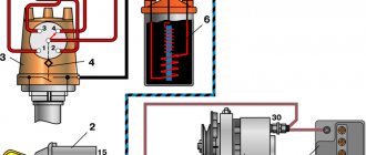
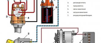
When the ignition is turned on, current begins to flow to the contacts of the distributor breaker. When starting the engine, the ignition distributor shaft rotates simultaneously with the crankshaft, which, with its cam, closes and opens the low voltage circuit. The pulses are supplied to the ignition coil, where the voltage is converted to high voltage, after which it is supplied to the central contact of the distributor. Then the voltage is distributed through the slider across the contacts of the cover and supplied to the spark plugs via explosive wires. In this way, a spark is formed and distributed.
Diagram of the VAZ 2101 ignition system: 1 - generator; 2 — ignition switch; 3 — ignition distributor; 4 — breaker cam; 5 — spark plugs; 6 — ignition coil; 7 - battery
Why is adjustment needed?
If the ignition is set incorrectly, many problems arise:
- power is lost;
- the motor is troublesome;
- fuel consumption increases;
- pops and shots appear in the silencer;
- unstable operation at idle, etc.
To avoid all of these difficulties, the ignition needs to be adjusted. Otherwise, normal operation of the vehicle will be impossible.
BB wires
High-voltage wires, or, as they are also called, spark plug wires, are different from all others installed in the car. The purpose of these wires is to transmit and carry voltage passing through them to the spark plugs and protect other elements of the vehicle from electrical charge.
Spark plug wires provide connection to the ignition coil, distributor and spark plugs
Malfunctions
The appearance of problems with explosive wires is accompanied by the following characteristic signs:
- problematic engine starting due to insufficient voltage on the spark plugs;
- shots at start-up and vibrations during further operation of the engine;
- unstable operation at idle speed;
- periodic engine tripping;
- the appearance of interference during the operation of the radio, which changes when the engine speed changes;
- smell of ozone in the engine compartment.
The main reasons that lead to problems with wires are wear and aging of the insulation. The location of the wires near the engine leads to temperature changes, especially in winter, as a result of which the insulation gradually cracks, moisture, oil, dust, etc. get inside. When cracks reach the conductor, the explosive wire can be pierced to ground, and a spark to the spark plug simply it won't arrive. In addition, wires often fail at the junction of the central conductor and the contact connectors on the spark plugs or ignition coil. To avoid mechanical damage, the wires must be correctly laid and secured with special clamps.
One of the malfunctions of high-voltage wires is a break
How to check
First, you should visually inspect the cables for damage to the insulating layer (cracks, chips, melting). Attention should also be paid to the contact elements: there should be no traces of oxidation or soot on them. Checking the central core of explosive wires can be done using a conventional digital multimeter. During diagnostics, a broken conductor is identified and the resistance is measured. The procedure consists of the following steps:
- Remove the spark plug wires.
Pull off the rubber caps with wires from the spark plugs - We set the resistance measurement limit on the multimeter to 3–10 kOhm and connect the wires in series. If the current-carrying wire breaks, there will be no resistance. A working cable should show about 5 kOhm.
Serviceable spark plug wires should have a resistance of about 5 kOhm
The resistance of the wires from the kit should not differ by more than 2–3 kOhm.
I check the wires for damage and spark breakdown as follows: in the dark, I start the engine and open the hood. If a spark strikes ground, it will be clearly visible, especially in wet weather - a spark will jump. After this, the damaged wire can be easily identified. In addition, one day I was faced with a situation where the engine began to misfire. I started checking with the spark plugs, since the wires had been replaced recently, but further diagnostics led to a malfunction in the cable - on one of them there was no contact with the terminal itself connecting the conductor to the spark plug. After contact was restored, the engine started running smoothly.
Video: checking explosive wires
Which ones to put
When choosing and purchasing high-voltage wires, you should pay attention to their markings. There are many manufacturers of the elements in question, but it is better to give preference to the following:
- BERU;
- NGK;
- PARTS-MALL;
- AMD;
- Bremi;
- Tesla Technics.
Today a large selection of spark plug wires is offered, but it is better to give preference to well-known manufacturers
Recently, more and more car owners prefer to purchase silicone explosive wires, which are characterized by higher strength and protection of the internal layers from high temperatures, abrasion, and aggressive chemicals.
Contact distributor
Stable engine operation is impossible without timely combustion of the working mixture. One of the main components in the ignition system is the distributor, or ignition distributor, which has the following functions:
- by disconnecting the contacts in the device, the beginning of sparking is set;
- the high voltage generated in the ignition coil is distributed to the desired spark plug;
- the beginning of the moment of spark formation changes;
- accumulation and discharge of energy in the coil is ensured.
The VAZ 2101 distributor consists of the following elements: 1 - spring cover holder; 2 — vacuum ignition timing regulator; 3 - weight; 4 — vacuum supply fitting; 5 - spring; 6 — rotor (runner); 7 — distributor cover; 8 — central electrode with a terminal for the wire from the ignition coil; 9 — side electrode with a terminal for the wire to the spark plug; 10 — central contact of the rotor (runner); 11 - resistor; 12 — external contact of the rotor; 13 — support plate of the ignition timing regulator; 14 - wire connecting the ignition distributor to the output of the primary winding of the ignition coil; 15 — breaker contact group; 16 — distributor body; 17 - capacitor; 18 — distributor roller
The distributor is called contact because in such a device the low voltage circuit, which is supplied to the ignition coil, is broken through a contact group. The distributor shaft is driven by the corresponding engine mechanisms, as a result of which a spark is supplied to the desired spark plug at a certain point in time.
Examination
To ensure stable operation of the power plant, periodic checking of the distributor is necessary. The main elements of the assembly that are subject to diagnosis are the cover, slider and contacts. The condition of these parts can be determined by visual inspection. There should be no signs of burning on the slider, and the resistor should have a resistance in the range of 4–6 kOhms, which can be determined with a multimeter.
The distributor slider should not be burnt, and the resistor should have a resistance of 4–6 kOhm
The distributor cap must be cleaned and inspected for cracks. The burnt contacts of the cover are cleaned, and if cracks are detected, the part is replaced with a whole one.
The distributor cap should not have cracks or severely burnt contacts.
The contacts of the distributor are also inspected, cleaned with fine sandpaper to prevent scorching and the gap is adjusted. If they are severely worn, they are also replaced. Depending on the current situation, more detailed diagnostics may be required, during which other problems may be identified.
If the breaker contacts are severely worn, they need to be replaced.
Adjusting the contact gap
The distance between the contacts on a standard VAZ 2101 distributor should be 0.35–0.45 mm. If there are deviations, the ignition system begins to malfunction, which affects the incorrect operation of the engine:
- power does not develop;
- the car jerks;
- fuel consumption increases.
Problems with the breaker occur due to the fact that the contacts are constantly working. Therefore, adjustments have to be done quite often, about once a month. The procedure is carried out using a flat screwdriver and a 38 wrench in the following order:
- With the engine off, remove the cover from the distributor.
- We rotate the crankshaft with a special key and set the breaker cam to a position in which the contacts will be maximally open.
- We evaluate the gap between the contacts with a feeler gauge. If it does not correspond to the required value, then loosen the corresponding fastening screws.
Check the gap between the contacts with a feeler gauge - We insert a flat screwdriver into groove “b” and turn the breaker stand to the desired amount.
Top view of the distributor: 1 - bearing of the movable plate of the breaker; 2 - oil can body; 3 — screws securing the rack with breaker contacts; 4 — terminal clamp screw; 5- bearing lock plate; b - groove for moving the stand with contacts - After completing the adjustment, tighten the fastening and adjusting screws.
After adjusting and checking the gap, it is necessary to tighten the adjusting and fastening screws
How to adjust the torque of the classic and “nine”
Let's now look at how adjustments are made in carburetor classics, for example, in the VAZ 2107. We will need:
- wrenches;
- light bulb with wires.
Begin.
- First of all, turn off the engine.
- We unscrew the spark plugs and carefully close the vacated holes in the cylinders with rag swabs.
- Set the piston of the first cylinder to top dead center. To do this, use the “38” key to turn the crankshaft in a clockwise direction until the mark of the crankshaft pulley aligns with the mark on the engine block. In this case, the tampon should fall out of the hole in the first cylinder. However, a block usually has three marks. The first means an advance of 10 degrees, the second - 5, the third - 0. We need the second.
- Screw in the candles.
- Loosen the nut securing the distributor.
- We connect one wire of the light bulb to the low-voltage terminal of the coil, and the second to ground.
- We get behind the wheel and turn the key to turn on the power.
- Let's return to the distributor. Rotate it very slowly clockwise until the light comes on and then goes out. Returning the distributor back, counterclockwise, we wait until the lamp lights up again, and the contacts separate. This is the right moment.
- Tighten the distributor fastening. The ignition adjustment of the rear-wheel drive VAZ is completed.
However, a front-wheel drive VAZ equipped with a carburetor has exactly the same spark excitation system. Therefore, the ignition adjustment of the VAZ 2109 is carried out according to similar instructions.
Now let’s look at the processes for setting up other systems below.
What to do with other cars
Let's look at how to adjust the ignition on a Buran snowmobile. For this you will need:
- strobe;
- keys, screwdrivers;
- sheet of paper, pencil, protractor, compass.
The actions are as follows.
- On a sheet of paper, draw a circle with a diameter equal to the size of the stationary element of the variator.
- Using a protractor, we mark the degrees around the circle from 0 to 30. Moreover, we put 0 at the top, where the clock shows noon.
- Having unscrewed the spark plugs, insert a screwdriver into the left cylinder.
- By turning the variator with your hand, we catch the moment when the screwdriver shows that the piston has reached top dead center.
- We put a mark on the variator opposite the zero of the scale we made.
- We connect the strobe to the high-voltage wire of the left cylinder, screw in the spark plugs.
- We start the engine, point the strobe light towards the scale. The device lamp should light up when a spark appears, and it should show which scale mark corresponds to the variator mark. This way we find out the existing advance angle.
- To install it, turn off the engine and loosen the magdino mount. Then we turn the magdino, maintaining the desired angle.
The setup is complete. But here you will have to buy a strobe to adjust the ignition angle.
Now let’s look at the adjustment process on the Ural motorcycle. Modern Ural motorcycles are equipped with a contactless system. However, sometimes it also needs adjustment. Let's see how this happens.
Next you need to prepare:
- wrenches, screwdriver;
- light bulb with wires.
Begin.
- Using the crankshaft mark, set the piston of the first cylinder to top dead center.
- The microprocessor unit, having loosened its fastening, is turned counterclockwise until it stops.
- The flywheel mark must match the motor mark.
- The light bulb should light up, one contact of which is connected to ground, and the second on the microprocessor unit.
- Turn the block further until the light goes out. This is the right moment. Tighten the fastening.
Next, we will study how ignition adjustment is done on the still popular ZIL-130 trucks. For work you will need:
Let's get started.
- First, unscrew the spark plug from the first cylinder and insert a paper plug in its place. We turn the crankshaft by hand, when the plug flies out, we align the mark of the crankshaft pulley with the mark of the timing gear block. The piston of the first cylinder should be at top dead center.
- We install the distributor drive in the cylinder block. We align the holes in the lower drive plate with the holes in the cylinder block. Tighten the bolts.
- We turn the crankshaft until the pulley mark is in front of the mark on the block between 3 and 6 combs.
- Using the adjusting screws, set the upper plate of the corrector to the “0” position of the lower plate.
- We turn the breaker by the body until the cam of the moving contact shaft is pressed out. Tighten the breaker fastening.
- We secure the high-voltage wires, start the engine, and check the operation of the system.
The same principle is used to adjust the ignition on the YaMZ 238 truck engine. Although for detailed instructions it is better to refer to the technical data sheet.
The same applies to ignition adjustment for Kamaz modifications. The presence of a high-pressure fuel pump in Kamaz makes it necessary to set the exact angle of injection of diesel fuel into the working cylinder.
An inaccuracy of one degree can lead to engine repair.
In general, in all cases, adjusting the correct ignition timing helps engine performance:
- firstly, it makes it easier to start;
- secondly, fuel consumption is optimized.
Settings price
But the car enthusiast is not always confident in his abilities. Sometimes it’s easier to go to a car service center to adjust the correct ignition timing.
We have indicated how much they will charge for this operation in large cities of Russia in the lines of this table.
| City | Price |
| Moscow | 400 rub. |
| St. Petersburg | 300 rub. |
| Ekaterinburg | 200 rub. |
| Krasnodar | 250 rub. |
Contactless distributor
The VAZ 2101 non-contact type ignition distributor is practically no different from the contact type, except that a Hall sensor is used instead of a mechanical breaker. This mechanism is modern and more reliable, since there is no need to constantly adjust the distance between the contacts. Structurally, the sensor is located on the distributor shaft and is made in the form of a permanent magnet with a screen and slots in it. When the shaft rotates, the screen holes pass through the magnet groove, which leads to changes in its field. Using the sensor, the distributor shaft revolutions are read, after which the information is sent to a switch that converts the signal into current.
A non-contact distributor is considered a more modern and reliable device
Diagnostics
The contactless ignition distributor is checked in the same way as the contact one, with the exception of the contacts themselves. Instead, attention is paid to the Hall sensor. If problems arise with it, the engine begins to work unstably, which manifests itself in the form of floating idle speed, problematic starting, and also twitching during acceleration. If the sensor fails completely, the engine will not be able to start. At the same time, problems with this element arise infrequently. A clear sign of a Hall sensor failure is the absence of a spark at the central contact of the ignition coil, so not a single spark plug will work.
The Hall sensor does not fail very often, and if this happens, the fault can be identified by the absence of a spark
You can check the part by replacing it with a known good one or by connecting a voltmeter to the output of the element. If it turns out to be working, the multimeter will show 0.4–11 V.
You can check the Hall sensor with a multimeter by connecting the device to the output of the device
Many years ago, I installed a contactless distributor on my car, after which I practically forgot what a distributor was and problems with ignition, since there was no longer a need to periodically clean the contacts from burning and adjust the gap. It is necessary to adjust the ignition only if any repair work is carried out on the engine, which happens quite rarely. As for the Hall sensor, during the entire operation of the contactless device (about 10 years) it has never changed.
Valve Adjustment Tools
To carry out quality repair work, you must have the appropriate tools. To adjust the valve mechanisms, you will need the following tools:
- Set of keys (socket and open-end). 13mm and 17mm wrenches are required.
- Feeler gauge for determining the gap.
- Screwdrivers.
- Felt pen.
- Rags.
The gap gauge for classic VAZ cars should be 0.15 mm thick.
After how many kilometers should the fuel filter be changed?
