Claim
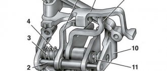
1. Gear shift fork (1) for axial shift of the clutch in the gearbox, having two sections (4, 5) of the fork arms lying opposite each other and interconnected by a transverse section (3) of the fork, characterized in that the sections (4 , 5) the fork arms and the cross section (3) of the fork are formed from wire or rod (7, 8).
2. Gear shift fork according to claim 1, characterized in that the rod element (7 has multiple bends.
3. Gear shift fork according to claim 1 or 2, characterized in that at least two rod elements (7) are combined to form the gear shift fork.
4. Gear shift fork according to claim 3, characterized in that in the transverse section (3) of the fork, the first rod element (7) and the second rod element (8) are connected to each other and are located in such a way that a gap (9) is formed between them .
5. A gear shift fork according to claim 3, characterized in that in the fork arm section (4, 5) the first rod element (7) and the second rod element (8) are located next to each other.
6. The gear shift fork according to claim 3, characterized in that in the section (4, 5) of the fork arm, the first rod element (7) and the second rod element (8) are spaced apart relative to each other.
7. The gear shift fork according to claim 3, characterized in that the first and second rod elements (7 are formed from a single piece of wire, physically representing a single structural element.
8. The gear shift fork according to claim 3, characterized in that each of the first and second rod elements (7) is formed from one piece of wire and they represent two structural elements.
9. Gear shift fork according to claim 1 or 2, characterized in that there is a sliding shoe (12) at the end (10, 11) of the shift fork arm (1).
10. Gear shift fork according to claim 1 or 2, characterized in that the rod element (7, at the end (10, 11) of the gear shift fork arm section (1) has a bend.
11. A gear shift fork according to claim 9, characterized in that the end (10, 11) of the fork arm section is bent substantially so as to have a U-shape.
12. The gear shift fork according to claim 11, characterized in that the curved (10, 11) end of the fork arm section forms a sliding eye (13).
13. Gear shift fork according to claim 12, characterized in that the sliding eye (13) is curved.
14. The gear shift fork according to claim 10, characterized in that the curved end (10, 11) of the fork arm section is provided with a sliding shoe (12).
15. Gear shift fork according to claim 1 or 2, characterized in that the rod element has a substantially circular and/or polygonal cross-section.
16. Gear shift fork according to claim 1 or 2, characterized in that the rod element is made of metal and/or plastic.
17. A gear shift fork according to claim 1 or 2, characterized in that the rod structure (P) in the transverse section (3) of the fork is firmly connected to the shift rod (2).
How the VAZ 2110 gearbox works
Volkswagen Passat Das graue Auto Logbook Replacing the gear shift cable
Before repairing, it is advisable to understand the operating principles of the gearbox installed on the VAZ 2110 model. The operating principle of the gear unit is as follows:
- The device contains a primary shaft consisting of a gear block. They are in constant mesh with the gears designed to move the car (drive gears);
- A drive gear is installed on the second shaft, on which the synchronizers are located. The bearing and oil sump are also installed here;
- by means of a flange, the driven gear of the main gear is connected to the two-satellite differential;
- elements of the device also include rods, ball joints, levers and switching mechanisms;
- so that the speed does not “take off”, the unit is equipped with a jet thrust, the ends of which are fixed to the power unit and support.
Switching gears on a VAZ 2110
Contrary to popular belief, keeping your foot on the clutch pedal within its (pedal) free play is harmless to the clutch. And holding the clutch pedal down for a long time (for example, at intersections) mainly harms the release bearing, and then mostly on cars where the release bearing rotates freely when the clutch pedal is released (GAZ, UAZ, “classic”, Niva, etc. .).
option 2: with a short, measured press of the gas, I bring the revolutions up to the appropriate ones (“the appropriate revolutions” are those at which, if you sharply release the clutch pedal, nothing will happen, i.e. there will be no jerk;
Mechanism - shifting - gearbox - transmission
| Gearbox synchronizer for GAZ-53A. |
Tuning the gear shift knob
The gearbox shift mechanism consists of forks 3, 7, 8 (see Fig. 96), mounted on sliders 27 - 29, a lever / shifter pressed by a spring 2 to the spherical surface of the cover 26, ball retainers 25, which prevent spontaneous switching on and off of gears , a lock that prevents the simultaneous engagement of two gears, and a spring fuse that makes it difficult to engage reverse gear.
| Gearbox of the GAZ-53A car. |
The gearbox shift mechanism must ensure proper engagement of the gears and prevent the gear from switching off on its own, engaging multiple gears at the same time, and engaging reverse gear when the vehicle is moving forward.
| Lubrication points for the clutch and gearbox with divider for KamAZ vehicles. |
Adjusting the gearbox shift mechanism involves changing the length of the intermediate rods to match the position of the gearshift lever to the corresponding position of the gearbox gears.
Adjusting the gearbox shift mechanism involves changing the length of the intermediate rods to match the position of the gearshift lever and gearbox gears.
Adjusting the gearbox shift mechanism (for cars with remote control) consists of changing the length of the intermediate rods in order to coordinate the position of the gearshift lever and gearbox gears.
Measures to eliminate the causes of the accident include: checking the technical condition of drilling rigs, gearbox shift mechanisms of T-170 B tractors; conducting extraordinary briefings to all employees of the drilling crews of seismic crew No. 2; removal from work of persons who do not have appropriate professional training.
The length of the rods associated with lever 4 (Fig. 61) of the control of the main clutch is set so that at the moment when the main clutch is completely disengaged, the UCM clutch is also disengaged, the UCM carrier is braked and the gearbox shift mechanism lock is fully opened.
Moving the movable gears and setting them to the desired position is carried out using a gear shift mechanism. The gear shift mechanism of the creeper is fundamentally the same as the design of the gearbox shift mechanism.
The controller serves for command control of the gear shift mechanism. The mechanism is located directly in the gearbox cover and has a number of power cylinders equal to the number of strokes of the gearbox shift mechanism. Each of the forks is mounted on a corresponding rod connected to one of the pistons. When compressed air is supplied to one of the cavities of the power cylinder 2, the piston 5 is displaced, and the return spring is compressed accordingly. When air escapes into the atmosphere, the spring returns the rod to the neutral position. The gear shift mechanism contains a block of eight electro-pneumatic valves, six of which provide air supply to the corresponding cavities of the power cylinders of five forward gears I - V and one reverse gear, and two (6 and 7) control the clutch.
| Transfer case with reduction gear. |
For this purpose, the transfer case switching mechanism has a special locking device that does not allow downshifting without engaging the front axle drive. The switching mechanism itself is located in the side cover and consists of sliders and forks, which are driven by two levers located in the driver’s cab. The operating principle of the transfer case shift mechanism is similar to the gearbox shift mechanism.
At diagnostic sites and TO-2 posts, it is advisable to carry out all the basic adjustment work on transmission units. The most common way to adjust the free play of the clutch pedal (for most domestic cars is 30 - 50 mm) is by the gap between the ends of the levers and clutch release bearings (1 5 - 4 mm), changing the length of the rod by rotating the nut or fork of the rod. For hydraulically driven clutches, the free play of the pedals is additionally adjusted by changing the gap between the pusher and the master cylinder piston. Adjusting the gearbox shift mechanism involves changing the length of the intermediate rods to match the position of the gearshift lever and gearbox gears.
CPT diseases
VAZ 2110 owners often complain that the first gear is difficult to engage or crashes.
- often the synchronizer is to blame;
- perhaps the clamp spring has burst, the lever is hanging loose, the speeds are switched on as desired;
- The stem and fork may need replacement.
Another complaint is that second gear is difficult to engage and often gets knocked out.
Here you can suspect the main culprits:
- the second one flies out most often because the gear teeth do not mesh well with the clutch that turns on the speeds;
- The tips of the gear teeth and clutch are already worn out, so the speed is difficult to engage. If you don’t intervene, it will soon fly out;
- as an option, when it knocks out on bumps, the clutch dies.
Sometimes (albeit rarely) when the second one does not turn on well enough and falls out, replacing the retaining spring helps. If the speeds often drop out, some of them are difficult to turn on, which means that half-measures will no longer help - the box needs to be overhauled.
Whether you do it yourself, or go to a service center where they will repair it for you and also adjust the gear shift mechanism, decide for yourself, based on your own experience and skills.
Difficulty engaging second gear, video
5 convenient gear shift knobs from AliExpress
The owner of the ten may encounter the same problems as when turning on the first speed. In any case, malfunctions are due to the following reasons:
- abrasion of gear teeth. At the first stages, the speed turns on poorly, but over time it will start to crash. Therefore, surgical intervention is required;
- there is insufficient adhesion of the gear to the gear shift clutch;
- the speed is switched off when hitting uneven road surfaces. In this case, the problem is the clutch.
Sometimes, to eliminate the knockout of the second gear, it is enough to replace the clamp. If replacement does not achieve the desired result, then a major overhaul is required.
Adjustment in this case will not solve the problem. Carrying out repair work yourself is quite difficult. Unlike adjusting and replacing oil seals, major repairs require professional skills.
Nuances, video
It should be noted that the gearbox is a fairly stable component of the vehicle. Compared to other units, breakdowns occur much less frequently here. At the same time, you need to remember that for the normal functioning of the box, you should change the oil in a timely manner, and use products from trusted brands. In terms of their performance, the gearboxes are almost identical. If we are talking about front-wheel drive cars, which include the VAZ-2110, then you can use oil poured into the power unit. If we are talking about rear-wheel drive VAZs, then special oil is provided for them. Sometimes car owners notice an oil leak. This is caused by weak fastening of the box and crankcase. The problem is solved with the help of seals, as well as careful tightening of the bolts.
If problems arise with the box, first of all it is necessary to adjust the drive and replace parts that have failed as a result of physical wear.
If the car owner has the skills and experience, then repairing the gearbox of a VAZ-2110 car can be done with his own hands. In other cases, it is better to visit a trusted auto repair shop and eliminate the deficiencies after professional diagnostics.
Help
If you haven’t coped with this task yourself or simply don’t want to bother with the work, you should contact a service station, which you can choose HERE.
Adjusting the rocker on a VAZ 2110 (video)
- Carefully inspect the boot. If oil leaks from the gearbox through the oil seal on your car, traces of it will definitely remain on the boot.
- Bend back the boot. This way you can get to the cardan, disconnect it and gain access to the cuff.
- You first need to dismantle the cardan from the lever, and only then from the rocker itself. Not the other way around.
- The cardan has been removed, so we move to the oil seal.
- The cuff is removed from the gearbox using a hook and an awl. Therefore, make sure you have these tools at hand in advance.
- Now a new one is installed in place of the old oil seal. Craftsmen have adapted to using ordinary plastic bottle caps. If you get used to it, it turns out to be very easy to change the oil seal.
- After replacing the element, return all dismantled components to their places. If some of them need replacing or signs of wear are already visible, it is better to replace them immediately. It is unlikely that you will want to repeat the same operation in a couple of weeks and lie under your own car.
The short walk is the result of independent tuning. Decide for yourself whether to carry out such work or not. But from the point of view of the efficiency of the gearbox, installing a short-throw rocker is only beneficial, since gears begin to shift more clearly.
Why did it happen
Perhaps the automatic requests do not belong to you, but to another user accessing the network from the same IP address as you. You need to enter the characters into the form once, after which we will remember you and be able to distinguish you from other users exiting from this IP. In this case, the page with the captcha will not bother you for quite a long time.
You may have add-ons installed in your browser that can make automatic search requests. In this case, we recommend that you disable them.
It is also possible that your computer is infected with a virus program that is using it to collect information. Maybe you should check your system for viruses.
If you have any problems or would like our support team, please use the feedback form.
How to change speeds on a VAZ 2110
In this position, the engine is disconnected from the transmission. The engine can be started. To prevent the vehicle from rolling on a slope, use the handbrake. To avoid overheating of the engine and transmission, the position “N” should be set when the vehicle is stopped for long periods of time (for example, in traffic jams). When waiting for a traffic light to allow movement, you should set the position to “D”.
If you have template 67.7834.9527, then set the gear shift knob as follows: with the lever cover removed, install the template in the trim window (number 14 in the diagram above) of the reverse locking bracket.
Fork - switching
The shift forks are connected to shift rollers, which can move in special holes in the upper half of the gearbox housing. The shift forks are held from axial movement along the shafts by locking screws. At one end of the shift rollers there are grooves for a locking device (locking) and clamps.
The switching fork for preparing to start the backup unit is installed by the maintenance personnel, who monitor the operation of the pumping station using the control and alarm panel.
The position of the doubler gear shift fork is adjusted so that when the accelerated gear series is engaged, the gap between the machined surface of the fork cheek and the end of the gear with internal teeth is 2 - 2 5 mm.
The shift fork rod is usually located near the steering column. The rod can be rotated and moved axially by a lever pivotally connected to it, located directly under the steering wheel. At the lower end of the steering column there are two levers, which, due to the movement of the rod, alternately engage with it, as a result of which they turn, thereby turning the gear on and off.
| Restoring a moving gear by replacing a worn ring. |
The grooves for the shift forks of the movable gears are machined until traces of wear are removed, and the forks are welded and processed according to the width of the enlarged groove.
Shift levers and forks, usually made of steel 18ХГТ and 40Х, may have the following defects: bending, cracks and breaks. The ball surface and lower end of the lever wear out. The thickness of the shift forks and the groove wear out.
Replacing the crayon of the gear shift fork of a screw-cutting lathe.
At the ends of the second and third gear shift forks, holes are drilled into which crackers are pressed; the crackers fit into the groove of the synchronizer carriage for shifting the second and third gears. The ends of the fourth and fifth gear shift fork end in a machined surface into which grooves are milled. The grooves of the fork accommodate the synchronizer ring for shifting the fourth and fifth gears.
In the forging of the shift fork, the curvature of the tab relative to the base plane of the boss and the difference between the planes in size I must be checked within a deviation of 0 5 mm.
A worn-out nut for switching the spindle gear block in the gearbox of a screw-cutting lathe model 1K62 from the Krasny Proletary plant was replaced only with the spindle removed.
The gap between the shift forks and the walls of the annular grooves of the gears should be 0 15 - 0 60 mm.
Reject levers and shift forks in case of kinks and emergency bends.
The sliding gear is moved by the shift fork 28 (see Fig.
Sometimes it is necessary to prevent the shift fork from turning on the guide pin. Then the rolling pin is rigidly tilted in the body (options b, d, e), and the fork is connected to the rolling pin with a guide key or splines.
Preparing to adjust the rocker
On an old car, it is better to lubricate the linkage mounting assembly with a penetrating compound in advance.
Before starting adjustment work, you need to prepare the place and carry out the following preparatory measures:
- The car needs to be parked in a pit.
- The handbrake must be tightened all the way.
- It is mandatory to install wheel chocks.
Operating principle of a manual transmission
The mechanical gearbox includes:
- The box itself, which is a multi-stage gearbox;
- Clutch;
- Various shafts and gears.
If we explain the principle of operation of a manual transmission for dummies, then we can form it like this:
- Gears change the speed of rotation between the shafts. By changing the size of the gears, switching to an up or down gear occurs;
- Without a clutch, changing gears on the move is impossible. Its job is to separate the engine and transmission. This procedure helps you change gears without breaking the gears and shaft.
Each manual transmission (if it is not an innovative model) has a similar design. Toothed gears are located on the shafts (on their axes). Manual transmissions come with two or three shafts, and the housing is called a crankcase.
Self-adjustment of the scenes on the VAZ-2110
The rocker of some well-known car models is a fairly firmly formed mechanism that can easily operate for more than 100,000 kilometers. But over time, its individual components begin to wear out prematurely, leading to the fact that the motorist is faced with numerous problems.
Each unit, component or part of the car, even the most insignificant, would seem to require a certain amount of care and timely adjustment. This also applies to the clutch of a manual transmission. A gearbox element that has been misadjusted can cause unpleasant sensations while driving. For example, it may happen that the gear shift knob begins to rattle, the gears will shift inaccurately or may periodically get knocked out, and the lever will begin to “play.” In order to get rid of such troubles, you should carry out a fairly simple procedure for adjusting the gearbox rocker. Moreover, this process will not take much effort from you, and it will last about half an hour.
Fork - shifting - gear
The side cover is installed in the gearbox housing with the gear shift forks in neutral position and the gear selector knuckle in neutral position. In this position, the switch fist should be in line with the lock protrusions.
True, the presence of a device connecting the lever on the steering column with the gear shift forks in the box slightly increases the cost of the transmission; however, placing the lever on the steering column has the advantage that it does not interfere with the driver's entry and exit from either the left or right side of the vehicle.
All moving gears of the box have special annular grooves into which the gear shift forks fit. The drive shaft of the power take-off gearbox passes freely inside it.
The synchronizer carriage 4 has a groove on its outer diameter into which the gear shift fork nuts fit. The internal hole of the carriage is slotted, consisting of three toothed rims.
| Remote gear shift mechanism MAZ-500. |
Ring 2, which has a recess for the gear shift fork, is attached to the protrusions 6 of the coupling flange with pins 5.
The outer diameter of the synchronizer carriage is processed in the form of a ring, with which it fits into the slots of the gear shift fork legs. Eight holes are drilled perpendicular to the blind holes around the circumference of the ring for installing blocking pins, and the axes of these holes intersect. The holes for the locking pins on both sides are chamfered with an angle corresponding to the angle of the chamfers of the locking pins. The carriage has internal and external gears. Internal splines, made in the form of two crowns, are designed to move the carriage along the secondary shaft. In addition, these rims, in combination with the four rims of the secondary shaft, when engaging fourth or fifth gear, form a lock that prevents the gear from turning off automatically while the vehicle is moving.
The pins 12 of the clutch fit into the inner annular groove of the holder 9, which has a recess on the outer surface for the gear shift fork. Clamps 14, consisting of balls and springs, hold the shift fork cage on the synchronizer body 11, protecting it from spontaneous movement.
When assembling the gearbox of a VAZ car, pay attention to the installation of balls with springs for the gear shift fork rod clamps in the crankcase. The spring for the reverse fork rod clamp ball is different from the others in its elasticity and therefore is painted green or has a cadmium coating
Before installing the forks, their condition is checked by external inspection. The bent of the forks is determined on a surface plate and, if necessary, they are straightened under a press in a cold state. Breaks and cracks on the cover, forks, rod heads and gear shift lever, as well as wear exceeding the permissible level, are not allowed. Worn balls of clamps and locks, as well as weakened springs, are replaced with new ones. If necessary, replace bearings and shafts.
The gearbox cover (Fig. 78) houses the gear shift mechanism, consisting of sliding rods, a lever and a gear shift fork.
The fingers 4 of the clutch, passing through the figured cutouts of the housing, enter the internal annular groove of the shift ring 2, which is connected to the gear shift fork. The synchronizer body moves along with the clutch until the bronze conical ring comes into contact with the conical surface of the hub of the engaged gear. Due to the difference in angular speeds of the gear and the synchronizer body, the latter will rotate through a certain angle under the influence of friction forces, and the protrusions of the coupling will rest against the edges of the figured cutouts 3, preventing its further movement. As soon as the angular velocities of the gear and the secondary shaft with which the clutch is connected are equal, the protrusions of the clutch will come out of the grooves and its further movement will again become possible. The ring gear of the clutch will engage the internal teeth of the engaged gear, connecting it to the output shaft.
To the protrusions 6 (see Fig. 69) of the coupling, which fit into the shaped slots 3 of the housing, the cage 2 of the gear shift fork is attached using pins.
To the protrusions 6 (see Fig. 89) of the coupling, which fit into the shaped slots 3 of the housing, the cage 2 of the gear shift fork is attached using pins.
| Gearbox synchronizer for MAZ-200 and KrAZ-219 vehicles. |
To the protrusions 6 (see Fig. 89) of the coupling, which fit into the shaped slots 3 of the housing, the gear shift fork cage 2 is attached using pins 5.
Self-adjustment of the scenes on the VAZ 2110
- Loosen the clamp.
- Engage reverse and position the lever as you would like it to be in that position.
- Then tighten the clamp and check how the rocker works, whether you are satisfied with the current position of the lever and the operation of the rocker.
- Turn on first speed.
- Loosen the rocker clamp.
- Turn the rocker drive counterclockwise until the gearshift lever begins to rest against the plastic reverse speed stop.
- Tighten the clamp and check how everything works.
We recommend reading: Minimum amount of arrest by bailiff
Three-shaft system design
The three-shaft system is equipped with three shafts:
- Drive shaft;
- Intermediate shaft;
- Driven shaft.
The driven shaft of a manual transmission is connected to the drive shaft using a bearing inside the first shaft and is positioned in such a way that the driven and drive axes are related to each other. In turn, this structure allows them to rotate independently of each other. The gears of the driven axle are not rigidly fixed in relation to the driven shaft, and the gears themselves have special delimiters - a synchronizer-clutch. Such delimiters, unlike gear blocks, are firmly attached to the driven shaft. However, this does not prevent them from moving along the Spitz along the axis.
The ends of the synchronizer clutch are shaped like toothed rims, which allows them to come into contact with the rims at the ends of the driven shaft gears. Currently, the gear unit is equipped with such synchronizers in all forward gears.
With a rear-wheel drive car, the transmission of torque and speed to the drive wheels occurs through the driveshaft, and with a front-wheel drive car, with the help of CV joints and a gearbox. If there is no gear and the clutch directly engages the driven and drive shafts, the gearbox provides the highest possible efficiency. For reverse gear, the gearbox device is equipped with a gear that allows you to change the direction of rotation in the reverse order.
Recently, manufacturers of manual transmissions have given preference to helical gears. Unlike spur gears, such gears produce minimal noise during operation and are more wear-resistant. The shelf life of such gears is determined by the material from which they are made: high-alloy steel, hardened by high-frequency current and normalized to relieve stress.
Why did it become difficult to change gears on the VAZ 2110?
Sincerely, Mikhail SH On the forum for 13 years Messages: 2738 From: Moscow Southern Administrative District Car: BMW E90 325iA Added: July 04, 2005 14:30 Quote: Then what is the reason for stupidity? Maybe it’s the engine itself? But 9 and 99 have the same engines, and their traction and acceleration are much better. I raced with a friend on the injection 9 3 times - he always beat me by almost 3-4 lengths at a distance of about 400 meters.
