- What's included in the rear suspension?
- Disassembling and replacing the rear suspension: instructions
- Front suspension device
- Disassembling and replacing the front suspension: instructions
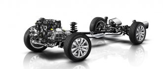
A complete set of VAZ 2114 chassis elements
The chassis of the car includes two suspensions - front and rear. During operation of the machine, most of the load falls on the chassis. The quality and comfort of the ride, as well as the safety of the driver and passengers, depend on the condition of the front and rear suspensions. The main function of each suspension is to eliminate vibrations and soften the ride. Also, the tasks of the chassis include reducing roll when turning, ensuring a smooth ride, and providing high information content for the driver in the city and on the highway.
On the roads of the CIS countries, the chassis is subject to excessive load, since the condition of the road surface leaves much to be desired. As a result, motorists often turn to car service centers. Things are better with the VAZ 2114, since it has more modern systems compared to previous Lada models. Many motorists choose to solve the problem on their own. But in order to understand what has gone wrong, you need to know the suspension structure.
What's included in the rear suspension?
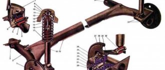
The image below shows all the main elements of the rear suspension that can fail.
Rear suspension diagram of VAZ 2114
- The first part is a rubber-metal hinge, which is the main attachment to the car body.
- A bracket used to secure the rear suspension arm to the body.
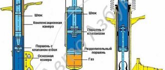
- Shock absorber housing.
- A buffer that takes the load from the compression stroke.
- Casing cover.
- Main support washer.
- Shock-absorbing cushion.
- Spacer sleeve.
- Strut (shock absorber).
- Insulation gasket.
- Solid spring.
- Connecting element for levers.
- Beam lever.
- Bracket for fastening the rack structure.
- Flange.
- Lever bushing.
The beam structure includes a connector and two trailing arms; these elements are indicated in the diagram as numbers “12” and “13”. The parts are fastened together by welding. In the rear part, flanges (number “15”) and brackets for attaching struts (shock absorbers) are attached to the levers. The axles of the rear pair of wheels along with the brake elements are screwed to the flanges. Bushings (16) are installed on the rear suspension arms at the front. They are fastened using rubber-metal hinges - number “1”. One end of the spring rests on the support through a rubber gasket, and the other on the shock-absorbing cup.
conclusions
The installation and repair of the front suspension of the VAZ-2114 is quite difficult and not every motorist can do it. This article examined the design and repair of the front suspension.
As you can see, there is a main group of parts that change when worn out and broken, and there are also a number of parts that are considered consumables and are replaced when the main components are repaired.
It is worth noting that suspension repair has a significant degree of danger, because the fall of one of the elements can lead to injury and even death. Therefore, when performing repair operations you must be extremely careful. Also, many suspension elements are quite heavy, so you need to have an assistant on hand.
Disassembling and replacing the rear suspension: instructions
The main parts of the rear suspension are highlighted in color
A complete disassembly of the rear suspension is required if the motorist decides to lubricate all the parts or change them. Most often you need to get to a specific element and replace it. The parsing proceeds as follows:
- The VAZ 2114 is installed under an inspection hole, or, as an option, on a lift. In the luggage compartment, the rear and side trims and the seat belt retractor are disconnected. Also in the luggage compartment there are fastenings for the racks to the car body. They need to be loosened; there is no need to unscrew them completely.
- Next, the fastenings of the rear wheel pair are loosened. To do this, you need to remove the hubcaps and then completely dismantle the wheels. Reliable jacks should hold the car at this time; they are usually installed on each side.
- Now it is necessary to dismantle the brake system cables. You need to get them assembled. To do this, the cable fastenings to the suspension arms and the body of the VAZ 2114 are disconnected. Afterwards, the brake drums are dismantled. The cable ends should be removed from the manual drive levers. You also need to disconnect the flanges from the brake flaps.
- Before dismantling the hoses and pipes of the brake system, care must be taken to prevent leakage. Next, you need to dismantle the elastic drive lever, which is used to operate the brake pressure regulator. To remove the lever, you need to disconnect it from the bracket by removing the lock washer, then remove the shackle from the wheel axle.
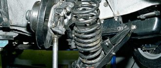
- The next step is to disconnect the struts (shock absorbers). To do this, remove the rubber cushions, nuts attaching to the body part and the washer. After this, you need to install additional stops for the front wheelset. The rear part should be raised. After this, you can remove the compression stroke buffers, springs and shock absorber covers.
- If you disconnect the body mounting brackets, the entire beam can be detached. The rear suspension along with the struts will lie in front of the motorist. If necessary, you can disassemble the shock absorbers, which is no longer difficult.
Components of the rear pillar of the VAZ 2114
IMPORTANT. The shock-absorbing spring must be removed using special ties. If they are not used, serious injury may occur as the iron spring is under high pressure.
Rear suspension
The diagram of this node includes a total of 16 elements:
- Rubber-metal hinge (it serves as the main fastener to the body);
- Bracket. It secures the rear suspension arm to the body;
- Shock absorber housing;
- Compression stroke load buffer;
- Housing cover;
- Support washer;
- Shock cushion;
- Spacer sleeve;
- Solid spring;
- Shock absorber;
- Beam lever;
- Insulation gasket;
- Lever connection element;
- Flange;
- Rack bracket;
- Lever bushing.
Disassembly and replacement
It is necessary to completely disassemble the rear suspension on the VAZ 2114 in cases where you want to fully lubricate the elements or replace some of them.
Dismantling is carried out according to the following scheme.
- The machine is driven into a viewing hole or raised using a lift.
- In the trunk, the lining and the belt reel are removed. There is also a fastener for the struts to the body, which is simply loosened a little. There is no need to unscrew it.
- Now the rear wheel pair fasteners are loosened. To do this, the caps are removed and the wheels are dismantled. Make sure that the jacks hold the car properly.
- Remove the brake cables. Here you need to unscrew the cable fasteners to the suspension arms and body. Next, the brake drum is removed, and the cable ends are removed through the manual drive lever. Do not forget to unscrew the flanges from the brake flaps at the same stage.
- At the next stage, the pipes and hoses from the brake system are removed and the drive lever is dismantled. It is used to operate the pressure regulator. To remove the lever, the bracket is disconnected by removing the washer and removing the earring from the wheel axle.
- After this you can disconnect the shock absorbers. Remove the rubber cushions, unscrew the fastening nuts and remove the washer from the body. Next, stops are placed under the front wheels and the rear part rises slightly. This will allow you to remove the buffer, springs and shock absorber housing.
- By unscrewing the body mounting bracket, you can dismantle the entire beam. This gives you full access to the rear suspension and struts. This even allows you to disassemble the shock absorbers themselves, replace them with new ones, and lower the VAZ 2114. Although, given the quality of our roads, this is not recommended. Do not forget that to remove the shock absorber, or rather the springs, you need to use special ties. If you don't have them in your garage, you may be seriously injured if you try to dismantle them without these tools. The spring is under high pressure, so it can easily jump out and cause injury to you.
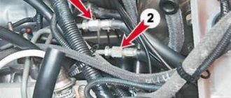
Front suspension device
The main element of the front chassis of the VAZ 2114 is the shock absorber strut, which is designated as number “9”. It is attached to the steering knuckle with two bolts. Compared to the rear system, the front suspension has a more complex design, which can be understood by the number of parts. Number “11” indicates a bolt that passes through the holes of the rack bracket; it has an eccentric washer and an eccentric collar. When the steering gear turns, the top bolt turns. The result is that the car turns. Most often, shock absorber struts fail, since they do the main job.
Diagram and explanations for it
Repair of the front suspension stabilizer of VAZ-2114
This element of the front suspension of the VAZ-2114 is designed to reduce the roll of the car when cornering. The part does not have a complex structure and consists of a flexible beam, as well as a pair of silicone silent blocks. The element has a small stroke, which ensures vehicle stability on the road.
Attached to the front side members with the central part. The side parts are connected to the suspension arm on the “knuckles”. The stabilizer has a long service life - more than 100 thousand kilometers. Usually it is the silent blocks that fail. But to replace them you need to remove the stabilizer completely. Below we will tell you how to do this.
If your car has lost its former maneuverability and strange noises have appeared in the front end, inspect the condition of the stabilizer. Perhaps the silent blocks in it have worn out. How to replace them? To do this you need:
- raise the front of the car;
- remove the bolts securing the struts from the right and left wheels;
- remove the bracket fixing nuts;
- remove the stabilizer assembly.
Disassembling and replacing the front suspension: instructions
- The VAZ 2114 is installed on a viewing hole or raised on a lift. The car must be set to the parking brake. It is necessary to remove the wheel caps, loosen the mounting bolts and unscrew the hub nut. Having secured the front of the car, you can remove the front wheels.
- Next, you need to remove the ball joint pin, which is located in the swing arm of the front strut. The next step is to remove the front stabilizer link (number “24”) from the front suspension arm (number “22”). Next, the stretch marks from the body (30) are removed. Next, you need to completely disconnect the ball joint that is attached to the steering knuckle.
- Now you can remove the front suspension arm. To do this, you need to disconnect it from the body bracket (28). Afterwards the lever is removed along with the bracket and the extension (29, 30). It is also necessary to remove the bolts that secure the pads to the steering knuckle.
- In front of the driver there will be a caliper assembly. To avoid problems with it, you do not need to completely remove it; you need to hang the caliper on a hook in such a way that there is no load on the main hose. The next step is to press the spline shank out of the front wheel hub.
- From the side of the engine compartment, you need to remove the protective fist (“41”). To do this, unscrew the telescopic strut nuts and then remove the solid front suspension strut. It should be together with the wheel hub and steering knuckle. The other front suspension strut is removed in the same way. Next, the racks are removed from the rod.
Removing springs using zip ties
When removing the bolts that secure the ball joint to the steering knuckle, you must use a socket wrench. Otherwise, the protective cover of the hinge may be seriously damaged, resulting in additional costs.
In the case of the front suspension, its assembly proceeds in the reverse order, with the exception of a few features. When installing the mounting bracket to the VAZ 2114 body, you need to make sure that the threads of the bushings are not damaged. To do this, you must perform operations carefully. Also, longitudinal displacement of the cushions on the bar must not be allowed. This can happen during installation of the anti-roll bar.
Start disassembling the front suspension
All work must be done on an overpass or pit. When replacing the VAZ-2114 suspension, try to use special tools - this will make the work much easier. The sequence is something like this:
- You definitely need to press the handbrake.
- Secure the rear wheels using wheel chocks.
- If decorative caps are installed on the rims, they must be removed.
- If the wheel bearing is being replaced, you will need to unlock and slightly unscrew the nut in advance.
- The wheel bolts also need to be loosened.
- Having lifted my side of the car that is being repaired, it is necessary to completely unscrew the wheel mounting bolts and completely remove it.
You will need to remove the braces from the stabilizer link. After this, using a puller, the ball joint is disconnected from the steering knuckle. It is screwed from below with two bolts; they must be removed using a “17” key. Without this, it will not be possible to dismantle the VAZ-2114 suspension arm.
Rack
This is one of the main elements of the front suspension of the VAZ-2114. The strut combines a spring and a hydraulic shock absorber. Thanks to this part, the suspension absorbs and absorbs bumps in the road. To allow the element to rotate (at the same angle as the front wheels), a support bearing is provided at the top.
The service life of the racks is about 100-120 thousand kilometers. What are the main symptoms of a malfunction? This
VAZ-2114, as well as “yaw” of the car when moving in a straight line at speeds above 60 kilometers per hour. The knocks are usually dull in nature and occur even on small irregularities. The sounds may become stronger over time.
VAZ 2114 suspension diagram and repair video
When using any car, its suspension wears out over time. Domestic car enthusiasts know that repairs to the VAZ 2114 chassis are required quite often due to poor roads in our country. How to repair the front or rear suspension of a VAZ 2114 with your own hands, we will look in detail in this material.
The VAZ chassis consists of front and rear suspensions. When operating a vehicle, they bear the greatest load. Their condition affects the quality and comfort of driving a car, as well as the safety of the driver and his passengers. The main function of car suspensions is to soften the ride and eliminate vibrations. The chassis also reduces roll when cornering and ensures a smooth ride, and also provides high information content to the driver in the city and on highways.
In the CIS countries, the roads are generally not very good, so the VAZ 2114 suspension experiences very high loads. This leads to the need to regularly contact a car service. At the same time, you can save your money by repairing the chassis of a domestic passenger car yourself in a garage. To be able to determine which element has failed, you need to know how the suspension works.
Rear suspension design
In the picture, the numbers indicate the main elements of the rear suspension of the VAZ 2114, which usually fail on bad roads.
Rear suspension diagram
- Number 1 in the picture shows a rubber-metal hinge - the main attachment to the car body.
- Bracket for attaching the rear suspension arm to the body.
- Shock absorber protective cover.
- A buffer that takes the load during compression.
- Casing cover.
- Main support washer.
- Cushion for shock absorption.
- Spacer sleeve.
- Shock absorber, also called strut.
- Insulation gasket.
- Spring.
- Connecting beam for levers.
- Beam lever.
- The bracket that secures the rack structure.
- Flange.
- Lever type bushing.
The beam design includes a connector and a pair of trailing arms. They are indicated in the diagram by numbers 12 and 13. The parts are connected by welding. In the rear part, flanges numbered 15 are attached to the levers, as well as brackets for fixing the shock absorbers.
The rear wheel axles with brake blocks are screwed to the flanges. There are bushings on the rear suspension arms at the front. They are held on rubber-metal hinges. One end of the spring rests on the support through a rubber gasket, and the other on the shock-absorbing cup.
How is the rear suspension disassembled?
To repair the rear suspension of a VAZ 2114, you need to know how to disassemble it correctly. We will tell you how to do this correctly below.
To begin with, the car must be placed above the inspection hole or raised using a lift. In the trunk, you need to disconnect the rear and side trim, as well as the seat belt retractor. Also here you need to find the fastenings of the struts to the car body and loosen them, but do not unscrew them completely.
Then you need to loosen the rear wheel mounts by removing the hubcaps and completely unscrewing the wheels. The machine must stand on reliable jacks - one on each side.
Front pillar
Remove the brake system cables. They should be removed as an assembly by disconnecting the cable fastenings to the chassis arms and body. After this, you need to remove the brake drums. Remove the ends from the manual drive levers and disconnect the flanges from the brake flaps. Before removing brake hoses and pipes, be careful not to leak. Next, remove the elastic drive lever, which is necessary for the operation of the brake pressure regulator. To remove the lever, disconnect it from the bracket by removing the lock washer, and then remove the shackle from the wheel axle.
Disconnect the shock absorbers by removing the rubber cushions, body mounting nuts and washer. Next, support the front wheelbase and lift the rear. Having done this, you can remove the compression stroke buffers, shock absorber covers and springs.
Once the body mount brackets are detached, you can remove the entire beam. In front of you will be a rear suspension with risers. If necessary, disassemble the shock absorber - this will not cause any special problems.
To remove the shock-absorbing spring, you will need special ties. Without them, you could be seriously injured because the spring is held in place under high pressure.
How the front suspension works
The key element of the front suspension of the VAZ 2114 is the shock absorber strut, which is indicated by number 9 in the figure below. It is secured with two bolts to the steering knuckle. Compared to the rear system, the front suspension has a more complex design - this can be seen in the number of parts. Number 11 indicates the bolt that goes through the holes in the rack bracket. It has an eccentric washer and a special belt. When the steering gear is turned, the top bolt turns. As a result, the car turns. Shock absorber struts, which carry the main load, usually fail.
VAZ 2114 front suspension diagram
We disassemble the front suspension with our own hands
Install the VAZ 2114 over the inspection hole or lift it on jacks or a lift. Be sure to set the parking brake when not using a lift. Remove the wheel caps and bolts, and then remove the wheels.
Next, remove the ball joint pin located in the strut swing arm. In the next step, remove the front stabilizer link number 24 from the suspension arm number 22. Then remove the braces from the body 30 and completely disconnect the ball joint that is attached to the steering knuckle.
Special ties
Remove the front suspension arm by disconnecting it from the body bracket number 28. After this, the arm can be removed with the bracket and extension. You should also remove the bolts that hold the pads to the steering knuckle.
In front of you you will see the assembled caliper. To avoid unnecessary work, do not remove it completely, but hang it on a wire so that the hose is not bent and does not experience stress. Then press the spline shank out of the wheel hub.
From the engine compartment, remove the protective cam number 41 by unscrewing the telescopic rack nuts, and then remove the solid suspension strut. It must be assembled with the wheel hub. In the same way, you need to remove the other front suspension strut, and then remove the struts from the rod.
When removing the bolts holding the ball joint to the steering knuckle, use a suitable socket wrench. Otherwise, you may damage the hinge protection case, which will result in unnecessary costs.
Do-it-yourself assembly of the front suspension of the VAZ 2114 is carried out in the reverse order. When installing the bracket, make sure that the threads of the bushings are not damaged. To do this, carry out all work carefully and do not allow longitudinal displacement of the cushions on the bar. This can happen when installing a stabilizer bar.
Video selection on VAZ 2114 suspension repair
Video:
Video:
Video:
Video:
driving24.ru
Description of the front suspension design
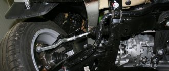
The front suspension is independent, with telescopic swivel struts, wishbones, longitudinal bracing arms and a torsion bar anti-roll bar.
The suspension strut consists of a housing in which a hydraulic telescopic shock absorber is installed, a coil spring and an upper support. A bracket for attaching the steering knuckle, a swing arm and a lower spring support cup are welded to the outside of the strut body.
Front suspension:
1 — extension bracket; 2 — longitudinal stretch; 3 — telescopic stand; 4 — transverse arm bracket; 5 — stabilizer strut; 6 — steering knuckle; 7 — ball joint; 8 — wishbone; 9 — bracket for fastening the stabilizer bar; 10 — stabilizer bar
The coil spring rests with its lower coil on the lower support cup, and with its upper coil on the upper support cup, mounted on the shock absorber rod. Also installed on the shock absorber rod is the upper support of the strut, consisting of a housing, a rubber cushion and a bearing. The support body is attached to the car body with three studs and nuts. The bearing allows the shock absorber rod to rotate in the support when the strut is turned, and the rubber buffer prevents the transfer of vibrations to the car body.
The shock absorber rod is protected from dirt and dust by a corrugated casing. In the event of a suspension breakdown, the stroke of the rod is limited by the compression stroke buffer.
The strut pivot arm is connected to the steering rod through a ball pin. Changing the length of the rod using its connecting coupling allows you to adjust the toe-in of the front wheels.
Tie rod coupling:
1 — steering rod; 2 - lock nut; 3 - coupling; 4 — tie rod end
The steering knuckle is attached to the strut bracket with two bolts and nuts. The upper hole of the bracket is made oval, and the bolt installed in it has an eccentric collar and an eccentric washer. When this bolt rotates, the steering knuckle moves relative to the strut, turning on the lower mounting bolt as if on an axle. Thanks to this, the angle between the strut and the fist changes, which, in turn, allows you to adjust the camber of the front wheel.
Attaching the steering knuckle to the strut:
1 — bracket for fastening the steering knuckle; 2 — rack body; 3 — bolt (eccentric) of the upper fastening of the steering knuckle; 4 — bolt of the lower fastening of the steering knuckle; 5 - steering knuckle
A double-row ball bearing is pressed into the hole of the steering knuckle and secured with two retaining rings. The wheel hub is pressed into the inner ring of the bearing.
At the bottom, the steering knuckle is connected to the wishbone of the suspension using a ball joint. The transverse lever is kept from moving by a stretcher, which is attached with its rear end through a rubber-metal hinge to the lever, and with its front end through a cushion to a bracket fixed to the car body. By changing the number of washers in the front and rear brace mounts, you can change the position of the lever, thereby adjusting the longitudinal inclination of the wheel steering axis.
Attaching the longitudinal brace to the transverse arm:
1 — rear end of the longitudinal extension; 2 — adjusting washers; 3 - thrust washer; 4 — rubber-metal hinge; 5 - transverse suspension arm
The ends of the anti-roll bar, using struts, are connected to the transverse arms of the front suspension of the car. The central part of the stabilizer is secured through rubber cushions to the body with brackets. The movement of one of the levers is transmitted through the stabilizer to the second. This allows you to partially synchronize the operation of both sides of the suspension and thereby reduce the sway of the car on uneven roads and roll in corners.
After repairing any suspension or steering components, be sure to check the alignment of the front wheels. It is possible to properly check and adjust the alignment angles of the front wheels only in a service company that has a special stand for performing adjustment work.
How to replace the lever?
To do this, raise the front part of the car (alternately on each side with a jack). Next, unscrew the nut securing the ball joint and, using a puller, remove the ball joint pin from the lever. Next, unscrew the nut securing the extension. The stabilizer link is disconnected from the lever. Next, unscrew the nut that secures the suspension arm to the body. If it is sour, use a “liquid key”. At the next stage, you can safely remove the lever from the stretch outward. The new part is installed in the reverse order.