What could happen to the car due to poor ground contact?
With the electrical equipment of any vehicle, malfunctions can occur that seem to people far from electricians to be the work of evil spirits.
And the culprit of mysterious malfunctions in the electrical equipment of a motorcycle or car, in most cases, is poor contact of the negative terminals - “ground”. But let's take things in order. Many drivers know that the method of connecting electricity consumers to a power source (generator or battery) on any vehicle is single-wire. The second (negative) wire is the body of a car or the frame of a motorcycle (trike, scooter, ATV, etc.). The very idea of connecting the negative side of a power source (battery) to a steel frame or body is quite old and natural, as it can significantly simplify, lighten and reduce the cost of any vehicle.
A separate ground wire is used to connect the engine to the body or frame, since the engine hangs on rubber mounts that do not allow current to pass through, while both plus and minus are required by the starter, and, for example, by the carburetor solenoid valve. On foreign cars, especially injection ones, there may be even more consumers requiring electricity (and, accordingly, plus and minus). But the positive wires usually begin and end with quite reliable terminals, which are usually in completely sealed plastic blocks or rubber covers, but the negative wires are attached to the body or frame according to the principle “some water will find a hole.” And the body itself, in the place where the hole is drilled and the negative wire is secured, begins to rust very quickly, unless, of course, appropriate measures are taken immediately.
In addition, many do not take into account another important fact, which is known even to a novice electrician: aluminum and copper terminals cannot be connected to each other, since these metals, to put it mildly, are “not friendly” with each other, and begin to oxidize intensively. How can oxidized parts have normal contact? But I often see on the vehicles of inexperienced drivers, on the aluminum housing of the gearbox or engine head, a screwed-on copper terminal of the negative wire, which, in addition, is also washed by streams of water in bad weather.
A steel body or frame is also not friendly with copper, like aluminum, and forms an electrochemical couple. And the saddest thing about this is that the steel in such a connection will be blown away by two people and will corrode several times faster. As a result, the contact disappears (or there is a significant loss of current). Standard terminals installed at the factory are usually tinned. But under a thin layer of tin, which is easy to tear off when installing the terminal, there is still the same copper alloy.
Based on the above, it is obvious that the negative connections themselves to the body or frame are initially less reliable than the copper wires themselves and their copper terminals (tips). Now imagine, for example, in order for electricity to reach the carburetor solenoid valve, the electric current must go along a copper wire (copper bus) from the battery to the body, then along another wire to the engine, then along the intake manifold studs and their threads, often coated with sealant (or the studs are rusty), and finally go along the threads of the solenoid valve itself. Loss of contact in any of the listed places - and the circuit is open, and hence a whole bunch of malfunctions. As a result, the inexperienced driver is surprised - why did the carburetor suddenly begin to work poorly and gasoline consumption increase? You need to go to a carburetor specialist or buy another carburetor. But usually few people know that in such a situation the carburetor has nothing to do with it. And I gave one example of a sudden malfunction, but there can be many of them.
Therefore, in modern cars or motorcycles, full-fledged negative wires are increasingly used, because modern on-board electronics will not work without them, and most devices or programs will fail. On such equipment, reliable contact is especially important. Experienced electricians know, and I have already said this: in electrics there are only two faults - there is a contact where it is not needed, and there is no contact where it is needed.
Typical malfunctions on a car due to poor ground contact (but not all, we read about the rest below) .
These malfunctions, as I already said, seem like miracles to inexperienced drivers. It is not uncommon at a factory (especially a domestic one) to place the negative terminal of the headlight on a stud or bolt securing the headlight housing to the body, and then tighten it with a nut. At first glance, many will think that everything is correct, because the stud or fastening bolt is welded to the body. But the headlight housing is made of soft plastic, and the nut on the terminal cannot be tightened properly, otherwise the plastic will crack. In the end, it only takes a short drive on our roads to weaken such contact to the point of its complete absence. But in a standard headlight with a modest lamp of 55-60 watts, the current consumed even by such a lamp is quite large - up to 10 amperes (if both its threads are energized, both high and low beam).
In the end, a bad contact, if it does not disappear completely, will burn out, the resistance of such a connection will increase even more, and from a school physics course we know that the greater the resistance, the more heat is released when current passes in this place. This means that the burning of contacts will intensify even more (a vicious circle), and it’s not far from a fire (plastic burns well). And many young novice drivers, instead of a standard 50-60 watt lamp, install a hundred (100 watt), which consumes even more current. The consequences can be dire.
Lada 2114 › Logbook › 1. Bad weight.
Hello everyone!) The first entry in this logbook gives a start)
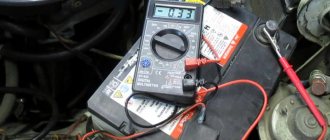
I'll start, as usual, with some background. A couple of months ago, once again moving from the village to the city, I turned off the engine before a closed railway crossing. Successfully drowned it out. It was not possible to start - instead of starter sounds there was absolute silence. I turned on the voltmeter reading on the dashboard - 8.8 volts. "What the?". Fortunately, the emergency lights still turned on. I waited until everyone had gone around, pushed the car over the crossing and started it with a pusher. I immediately look at the tidy - 13.1 volts, not enough. I took out a multimeter and checked it at the battery terminals - 13.2 V. I stood there and thought - you still won’t find many faults in the middle of the road, but you have to go. On the road, the voltage jumped from 11 to 13.5 volts. I reached my final destination without ever turning off the engine, and, as it turned out, not in vain. As soon as I parked, I turn off the engine, turn on the voltmeter - the same 8.9 - 9 volts on the battery.
I started blaming the dead battery. I took it to a nearby auto repair shop for charging. He stayed with them for a day. I picked it up and installed it - 13.3 c. With the engine running - 13.9. Strange. The next day I had to go, I sat down to warm it up, I looked - 13.2, 13.1 and it dropped. When it warmed up to 60, it was generally 12.4. Turned on the light - 11.9. As a result, I drove like this for three weeks while I looked for what the problem was. Akkum behaved well.
All three weeks the problem was floating - sometimes the voltage was normal, sometimes it dropped to 11.5 volts. First of all, I cleaned and stretched all the power connections, including the mass ones. Replacing the LV did not produce any results, and a complete revision of the generator also turned out to be useless. And only then Lesha Hot-tabi4 pointed out to me that the tension is really lost on a bad mass. The voltage drop between the engine and the battery terminal ranged from 0.5 to 1.6 volts. They also found a very hot wire from the battery to ground - when the consumers were turned on, it was impossible to hold on to it.
Since there was no desire to tinker under the hood in dirty and wet weather, on Lehi’s advice I decided to lay additional massive wires. I took a couple of meters of copper wire with a cross-section of 4 mm^2, several crimp terminals and in the evening I made 3 wires - from the generator to ground, from the generator to the battery and from the battery to ground. At that time, red wires were available, unfortunately, because I don’t really like the look of them under the hood, they stand out too brightly.
I installed them the next morning. I pulled all the connections, the key to start, aaand... 14.2 volts when cold, as it warms up it drops a little and stays at 14.0. When turning on the lights, heating the glass and the stove - 13.6 V. When driving for a long time in one mode, for example, on a highway, the voltage increases. networks even with consumers rises to 14.0 v. In the city, temperatures below 13.4 were not observed. The ground wire is cold.
I’ll drive like this until it warms up, and then I’ll figure out where the factory weight went from the engine. But I probably won’t remove these wires, I’ll just replace them with black ones and route them more carefully.
In general, the reason turned out to be very banal, but I simply did not expect that in three years of the simplest operation a lot could disappear...
Thank you for reading!) Good luck to everyone on the roads!)
Source
.3.3. Poor Ground Detection
The negative terminal of the battery is connected to “ground” - the metal of the body, engine or gearbox; Moreover, many elements of electrical equipment are connected in such a way that only the positive wire is suitable for them, while the current returns to the battery through the metal of the body. This means that the electrical component mount and the body are part of the electrical circuit. As a result, poor or corroded fasteners can cause the element to fail or cause it to perform erratically or poorly. In particular, light bulbs may glow dimly (especially if the light bulb's ground point is connected to another electrical component that is still on), electric motors may run slowly, and the operation of one circuit may have a seemingly unnoticeable effect on the operation of another circuit.
Don't forget that many vehicles use ground wires between certain components such as the engine/transmission and the body, that is, in areas where there is no direct metal-to-metal contact due to soft rubber mounts or a layer of paint.
To check the reliability of the element's grounding, it is necessary to disconnect the battery and connect one of the ohmmeter probes to a reliably grounded element. Connect another probe to the wire or connection to the body that needs to be checked. The resistance shown by the ohmmeter should be zero; if not, check the connection as follows.
If you suspect there is no ground, disassemble the connection and clean the body area and wire terminal (or the grounding surface of the element) to bare metal. Carefully remove all traces of dirt, then use a knife to remove all paint so that there is reliable contact between the two metal surfaces.
Also interesting: What is the difference between the Niva Urban and the regular Niva?
When assembling, tighten the connector securely; When connecting a wire terminal, install a serrated washer between the terminal and the body surface to ensure a secure connection. When connecting, prevent future corrosion by applying a layer of Vaseline or silicone grease.
Where is the mass of the Chevrolet Niva engine?
But if everything is in order with the relay, and the devices do not work, then there may be a problem elsewhere - the mass attachment point. The negative wire coming out of the battery is connected to the car body and goes to some of the main energy consumers in the form of wires. This is sometimes the difficulty when calling an electrician.
The architecture of the circuit can be described as follows: a wiring harness comes out of the negative terminal, connecting devices operating from one ground point, then wires connecting other ground points are connected to them using a crimp sleeve. As a result, finding a specific mass attachment point is quite difficult.
For example, the mass of the mirror control unit is located behind the trunk trim. But with the engine everything is a little simpler. Since it is connected to the frame and body through pads, which are essentially a dielectric, it has its own wiring harness. The terminals are located on the left side of the engine, below the ignition module. They are responsible for the operation of the ECU and ECM sensors.
Diagram of the instrument cluster of a high VAZ 2109 panel with an on-board control system
The instrument clusters of the “high” panel and the “European panel” are equipped with an on-board control system. This combination of instruments includes: a speedometer with daily and total distance meters, a coolant temperature indicator, a fuel level indicator, a tachometer, 13 warning lamps and an on-board control system unit (BSK). Diagram of the VAZ 2109 instrument cluster with a “high” panel with on-board control system (manufactured before 1996):
1 - relay-breaker for the parking brake warning lamp2 - tachometer with voltage stabilizer3 - instrument cluster illumination lamp4 - temperature indicator5 - BSK control unit6 - fuel level indicator7 - resistor 50 Ohm, 5 W8 - "CHECK ENGINE" indicator lamp for the toxicity reduction system9 - control headlight high beam lamp10 - side light indicator lamp11 - backup indicator lamp12 - seat belt warning indicator13 - left turn indicator indicator indicator14 - resistor 470 Ohm, 0.25 W15 - electronic voltmeter16 - right turn indicator indicator indicator17 - emergency oil pressure indicator indicator18 — fuel reserve warning light 19 — carburetor air damper warning light 20 — “CHECK ENGINE” warning light for the fuel injection system 21 — parking brake warning light Diagram of the VAZ 2109 instrument cluster with a “high” panel with an on-board control system (manufactured after 1996):
1 - tachometer2 - instrument cluster illumination lamp3 - temperature gauge4 - BSK control unit5 - fuel level indicator6 - "CHECK ENGINE" indicator lamp for the toxicity reduction system7 - headlight high beam indicator lamp8 - side light indicator lamp9 - reserve indicator lamp10 - unfastened indicator lamp seat belts11 - left turn indicator indicator lamp12 - battery charge indicator lamp13 - right turn indicator indicator lamp14 - emergency oil pressure indicator lamp15 - fuel reserve indicator lamp16 - carburetor air damper indicator lamp17 - "CHECK ENGINE" indicator lamp for the fuel injection system18 - control lamp parking brake lampB1 - 91 kOhm resistorB2 - 50 Ohm resistor, 5 WPinout of connectors for the VAZ 2109 instrument cluster with on-board control system
| Plug no. | Address (purpose) of the plug |
| White connector | |
| 12345678910111213 | Reserve outputReserve output To the seat belt relayFuse “5” for instrument protection (“+” for the direction indicator and hazard warning relay relays——To fuse “7” for the protection of interior and exterior lighting lampsTo fuse “14” for the high beam protection of the left headlightReserve outputTo the level sensor fuel (output for the fuel level indicator) To terminal “61” of the generator To the temperature indicator sensor |
| Red connector | |
| 12345678910111213 | — Fuse “5” for instrument protection (“+” for powering instruments) To terminal “K” of the ignition coil To the instrument lighting switch To the fuel injection system control unit — To “ground” To the parking brake switch Reserve terminal To the carburetor air damper warning lamp switch To the fuel level sensor ( output for the fuel reserve warning lamp) To the oil pressure warning lamp sensor To terminal “49aR” of the turn signal and hazard warning lamp relay |
| 9-terminal connector (for BSK) | |
| 123456789 | Fuse “5” for instrument protection (“+” power supply) To terminal “50” of the ignition switch To “ground” To the washer fluid level sensor To the oil level sensor To the coolant level sensor To the brake fluid level sensor To the brake lining wear sensors To terminal “3” of the lamp health monitoring relay |
Solutions to the problem
If power outages occur frequently or current leakage occurs during long periods of parking, you can improve the system to solve the problem. It’s not difficult to get the job done; the minimum set of tools that every motorist should have is enough. The procedure depends on the nature of the malfunction.
How to make mass better
If removing and cleaning the contacts does not produce any effect, you will have to use more radical repair methods. In some models, the problem with a minus on the body is a real “disease”, so it is necessary to improve the design in order to eliminate the manufacturer’s shortcomings:
It is necessary to monitor the condition of the wires and replace them if there is even the slightest doubt about reliability. It is best to use the same elements as those installed, plus high-quality fasteners.
Installing the mains switch
The switch will protect the car from current leakage, short circuit, and can also serve as an additional anti-theft system. It’s easy to install it yourself; most often, one of two options is used:
The switch is not suitable for cars with an alarm and central locking, since if there is no ground, the system will not work. It is also undesirable to install it on models with a lot of electronics.
It is not difficult to locate the ground wires; they should be periodically removed and processed to ensure good contact. When checking, it is better to use a multimeter, this is the easiest way to detect damage if it is present. It is recommended to replace worn wires in a timely manner, and to prevent leaks, you can install a power switch button.
Vesta
Required
: wire (article AX632).
The on-board computer used to show a voltage of 14.0-14.1 V, now it’s 14.1-14.3 V. I don’t notice any shuddering when the fan is activated.
Another example of installing additional mass on Vesta:
It’s similar on other LADA models.
Let us remind you that the voltage in the car's electrical system should be 14.2-14.4 Volts.
Source
Where is the ignition relay located on a Niva Chevrolet?
The ignition relay is located in the passenger compartment fuse box; it can be found on the driver's side of the instrument panel, opposite the seat. On the diagram it is usually designated K6 and in the technical description it is sometimes called an addition relay.
Also interesting: Niva-Chevrolet with an Opel engine: brief description, technical characteristics, owner reviews
It is responsible for turning on the fuel pump and supplying voltage to other elements. Triggered when the ignition key is turned. At this moment, you can hear a click behind the instrument panel. This electric coil built into the relay receives voltage and closes the contacts of a certain circuit. If there is no characteristic sound when turning the key, this may indicate its failure.
ADDITIONAL MASS WIRES
If the weight of the engine with the body is bad, then problems arise:
When symptoms of poor engine weight appear, there is a way out of the unpleasant situation - in this case, additional weight on the engine will help. You can install an additional wire in different ways, the most important thing is that it reliably connects the car body with the power unit. For example, one end of the wire can be attached to the stud of the upper shock absorber support, and the other to the stud of the intake manifold of the internal combustion engine. It is important that the wire has a large cross-section, preferably no less than that of the bulk itself.
On new machines, problems with mass wires rarely occur. But on older models, the body studs rust. Finding a lack of ground is not so easy, so car owners use the installation of additional wires. So the additional mass on the generator helps eliminate battery charging leakage.
Granta, Kalina Priora
On front-wheel drive LADA cars (Priora, Kalina Granta), the ground wire from the negative terminal of the battery is attached to the thermostat housing. This is a bad decision because... The thermostat is isolated by a gasket and all current flows through two studs. During operation, the contact oxidizes and the voltage in the on-board network drops, difficulties appear in starting the engine, etc. The problem can be solved with a simple modification.
You should move the negative wire coming from the battery from the thermostat to the engine:
Or install an additional wire from the thermostat to the engine (photo diamond1309):
It would not be a bad idea to additionally extend the ground from the negative terminal of the battery to the body and generator: