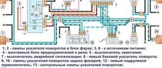
What does the electrical circuit of a VAZ-21213 or, in other words, Niva (carburetor) look like? This question worries mainly those owners who are trying to independently repair any element that has become unusable.
In reality, the circuit contains almost a hundred components and devices, so in this article we will only talk about individual electrical circuits that most often fail.
Circuit breakers
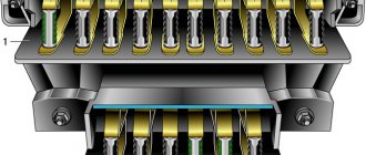
The block of protective devices in Niva is a board on which disposable fuses are installed, containing a fuse inside. Each of them protects one or more electrical circuits from overvoltage.
The unit is located in the cabin on the left side. Protective equipment is numbered. So, 1 is responsible for the work:
- windshield washer;
- stove fan;
- cleaners for all headlights;
- heating, wiper and washer for tailgate glass.
Instrument cluster diagram, instrument cluster troubleshooting
The components of the instrument cluster are not supplied as spare parts, therefore, in the event of failure of one of the instruments, the combination must be replaced as an assembly.
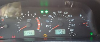
All vehicle control devices are combined into an instrument cluster. It includes: a speedometer with a trip meter, a coolant temperature indicator, a fuel level indicator, a tachometer, and warning lights.
Since 2009, Lada Niva 4×4 cars have been equipped with an electronic instrument cluster borrowed from the Samara-2 family.
It includes an electronic speedometer and tachometer, a liquid crystal indicator of the total and daily mileage counter (odometer), a liquid crystal display of the clock and ambient temperature, a coolant temperature indicator, a fuel level indicator, twelve signaling devices and six backlight lamps.
The operation of the devices is controlled by an electronic module, which receives signals from sensors. Temperature and fuel level indicators are of electromagnetic type. The tachometer and speedometer needles are driven by stepper electric motors.
Connection diagram of the instrument panel wiring harness (after 2009)
Connection diagram of the instrument cluster produced since 1996. (inside view)
The coolant temperature gauge works in conjunction with a sensor screwed into the cylinder head. The sensor contains a thermistor (a resistor that changes its resistance depending on temperature).
Data for checking the coolant temperature gauge sensor
| Temperature, °C | Voltage at the sensor, V | Sensor resistance, Ohm |
| 30 | 8 | 1350–1880 |
| 50 | 7,6 | 585–820 |
| 70 | 6,85 | 280–390 |
| 90 | 5,8 | 155–196 |
| 110 | 4,7 | 87–109 |
Data for checking the coolant temperature gauge
| Indicator arrow position (with on-board voltage 13–14 V) | Temperature sensor resistance, Ohm |
| At the beginning of the scale | 640–1320 |
| At the beginning of the red zone | 77–89 |
| 40–50 |
If the pointer needle is constantly at the beginning of the scale, with the ignition on, disconnect the wire from the sensor and connect it to ground through a 20–50 Ohm resistor (4–5 W light bulb, relay winding). If the arrow deviates, the sensor is faulty.
If the arrow does not deviate, remove the instrument cluster, disconnect the red block from it and, with the ignition on, connect plug “13” of the white block to ground through a 20–50 Ohm resistor. If the arrow has now deviated, the sensor-pointer circuit is faulty. If not, the pointer or its power circuit is faulty.
If the indicator needle is constantly in the red zone, disconnect the wire from the sensor with the ignition on. If the arrow deviates to the beginning of the scale, the sensor is faulty; if not, the wire shorts to ground or the indicator does not work. The latter can be checked by disconnecting the white block from the instrument cluster.
In this case, a working indicator (with the ignition on) should have an arrow at the beginning of the scale.
The fuel level indicator works in conjunction with a sensor installed in the fuel tank. The sensor is a rheostat with a resistor made of nichrome wire. The movable contact of the rheostat is moved by a lever with a float. At the end of the lever there is an additional contact that closes the circuit of the fuel reserve warning lamp when 4–6 liters of gasoline remain in the tank.
Data for checking the fuel level sensor
| Fuel level | Sensor resistance, Ohm |
| Empty tank | 250±12 |
| Half filled | 66±6 |
| Full tank | 20±3 |
Data for checking the fuel level indicator
| Indicator arrow position (with on-board voltage 13–14 V) | Sensor resistance, Ohm |
| At the beginning of the scale | 238–262 |
| In the middle of the scale | 59–71 |
| At the end of the scale | 17–23 |
If the gauge needle is constantly at the beginning of the scale (indicating an empty tank), with the ignition on, disconnect the pink wire from the sensor and connect it to ground. If the arrow deviates towards the end of the scale, the sensor or the circuit connecting it to ground is faulty.
If the arrow does not deviate, remove the instrument cluster, disconnect the white block from it and, with the ignition on, through a 20–50 Ohm resistor (4–5 W light bulb, relay winding) connect its plug “11” to ground. If the arrow now deviates, the sensor-pointer circuit is faulty. If not, the pointer or its power circuit is faulty.
If the gauge arrow constantly shows a full tank, with the ignition on, disconnect the wire from the sensor. If the arrow deviates to the beginning of the scale, the sensor is faulty; if not, the wire shorts to ground or the indicator does not work. The latter can be checked by disconnecting the white block of wires from the instrument cluster.
In this case, a working indicator (with the ignition on) should have an arrow near o.
The tachometer and speedometer are checked on special stands. As a rule, disturbances in their operation are associated with oxidation of contacts in the supply and control circuits, or (for the speedometer) with improper installation, or damage to the cable or its drive.
If control devices or their sensors fail, they are replaced.
Source: https://lada-niva.ru/niva/21-13-1.html
Dashboard
All control devices are interconnected. This combination consists in particular of:
- speedometer;
- tachometer;
- coolant temperature indicator;
- 12 indicator lamps;
- battery charge sensor;
- fuel level indicator.
All of them are located on the panel.
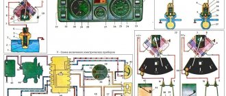
The schematic diagram shows the combinations available on the instrument panel:
- tachometer (1);
- stabilizer (2);
- panel illumination (3);
- coolant heating indicator (4);
- gasoline level (5);
Warning lamps:
- toxicity reduction systems (6);
- heated luggage door glass (7);
- fog lights (8);
- high beam (9);
- outdoor lighting (10);
- turn signals (11);
- TG level (13);
- oil pressure (14);
- differential locks (15);
- fuel reserve (16);
- seat belts (17);
- parking brake (18).
D1, D2 are diodes (type IN4002).
Cars manufactured before 1996 also have a voltmeter (12 in the diagram).
Finally, there are two resistors:
- R1 – at 470 Ohm (0.25 W);
- R2 –51 Ohm, (5 W).
Pinout of the instrument panel VAZ 2121
| Plug no. | Plug address | |
| Block X1 (red or orange) | Block X2 (white or other color except red/orange) | |
| 1. | ─ | ─ |
| 2. | To terminal “15” of the ignition switch | High beam warning lamp |
| 3. | Low voltage tachometer input | To the gab. lighting (control lamp) |
| 4. | To the instrument lighting control | To terminal “15” of the ignition switch |
| 5. | High voltage tachometer input | To hazard warning switch |
| 6. | Housing (weight) | To output "D" of the generator |
| 7. | To terminal “50” of the ignition switch (starter) | ─ |
| 8. | To the parking brake warning lamp switch | Fog lamp warning lamp |
| 9. | ─ | Rear window heating indicator lamp |
| 10. | To the fuel reserve lamp | Check Engine |
| 11. | To differential lock sensor | To fuel level sensor |
| 12. | To emergency oil pressure sensor | Check Engine |
| 13. | To brake fluid level sensor | To coolant temperature sensor |
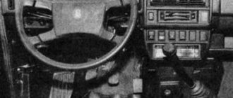
Removal and installation instructions
How to remove and install the dashboard on a Niva:
- First, you need to remove two plugs from the control panel lining and unscrew the screws. Next, unscrew the screws that secure the tidy visor.
- The right side of the panel facing is pulled out, the pads from the keys are removed, as well as the connector. Next, the control panel trim is removed from the left side; by doing this, you can dismantle the button for activating the side lights and optics. After this, the panel lining can be completely dismantled.
- The two screws of the tidy are unscrewed, the shield itself is removed, and all connectors and plugs are disconnected. If there are problems with the operation of the shield, they are resolved at this stage. The device is being repaired, it is soldered, and burnt-out light bulbs are replaced.
- Next, the shield is installed. When installing, keep in mind that the holes in the steel strip located under the tidy must line up correctly. Further installation is carried out in the reverse order of removal.
Maintenance of wiring VAZ 21214 and other Niva models injector and carburetor: electrical diagram
Detailed electrical diagram of Niva
The wiring diagram may vary slightly depending on the design features of the vehicle.
First, let's look at the index notation:
- VAZ 21213. This index designates a vehicle equipped with a carburetor. The volume of the power unit is 1.7 liters.
- 21214. In VAZ 21214 cars, the scheme involves the use of a similar engine with the same volume. The only difference is that the car is equipped with a fuel injection system.
- There is another model with the index 21213. In VAZ 21213 cars, the electrical circuit includes the same elements, only depending on the year of manufacture, the car can be equipped with a 1.8 liter engine.
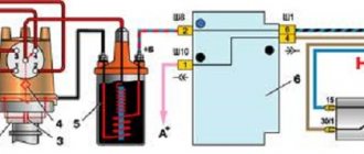
- Version 21073. The SUV is equipped with either an injection engine with nozzles or a Solex carburetor engine. One of the features of these cars is a contactless ignition circuit.
- 21215. These SUVs were originally produced for export, so these cars are difficult to find on our roads. It is worth noting that they were equipped with Citroen diesel engines.
At the beginning of the article there is a diagram of the VAZ electrical equipment using the example of the Niva 2121 model. If you are the owner of version 2131 or any other, then there will be a difference in the circuit diagram, but not fundamentally. If we are talking about carburetor engines, then in this case the battery charging circuit, as well as the ignition, will not be protected (video author - Nail Poroshin).
Features of electrical equipment
The electrical circuit of the VAZ model 21213 has certain differences with the model 2121, in particular:
- 21213 vehicles use more modernized foot fuses in the fuse box. Of course, the use of such devices led to the fact that the block site also became different.
- The power supply system of these vehicles additionally includes an idle speed saving device. For this option to work properly, another connector with wiring was added in the engine compartment.
- Another difference is that these cars use a non-contact ignition circuit, the main element of which is a microcontroller.
It should be noted that differences in the Niva circuit may lie both in the generator units and in the electrics themselves.
Differences in generators
In any case, the differences in the wiring diagram of the models will primarily depend on the power unit - carburetor or injection.
The main differences in carburetors:
- models 21213 use the generator unit model 371.3701;
- in the engines of models 21214, the manufacturer decided to install a more powerful generator device; it is marked with the numbers 9412.3701 (video author - Sergei Chekhonin).
And although these generators are different, they have certain similarities in design. In any case, it is a synchronous AC device. In addition, these units have a built-in rectifier and output voltage regulation mechanism.
Wiring differences
If we talk directly about wiring, then depending on the car model, it may also have differences. It should be noted that these differences greatly simplify do-it-yourself maintenance and repair of the system. As for injection modifications of SUVs specifically, in this case the system is equipped with three outputs intended for installing electronic ignition.
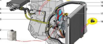
In addition, 21214 cars use two ventilating devices that perform the function of cooling the radiator assembly. Accordingly, due to the use of additional fans, the wiring also underwent, albeit not significant, differences. Of course, they are not fundamental.
Photo gallery "Electrical systems of SUVs"
1. System designations in 21212. Electrical diagram of Niva 2123
Summarizing
The need to understand the wiring diagram may arise if there are malfunctions in the operation of the system and they need to be eliminated.
Of course, complex malfunctions associated with the operation of the generator unit and other devices that are not simple in terms of design will be problematic to solve in a garage without certain knowledge.
However, even simple knowledge of the electrical circuit and the ability to decipher the symbols can greatly help the car enthusiast during repairs. In addition, the need to understand wiring may also arise if you decide to upgrade your speakers or install a more advanced audio system.
Source: https://avtoklema.com/skhema/jelektrooborudovanija-niva-vaz-21213-629/